Optimal part orientation and support configuration in a 3D printer
One of the main advantages of additive manufacturing is the possibility of real customization of parts. This technology is well-suited for the production of customized implants for patients in medical fields such as craniofacial surgery (CFS), where optimal size, shape and mechanical properties are required.
- Objective: Demonstrate that modeling can help in choosing the right orientation and configuration of the supporting structure.
- Solution: Create three different part support configurations and compare them
- Used Software: Materialize Magics
- Method: modeling and comparing deformations of final part support configurations
- Industry sector: Healthcare
Problems of 3D printing of cranial-maxillofacial implants
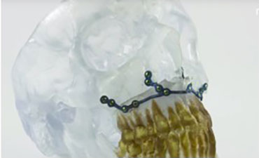
Individual maxillofacial implant

The effect of "springing"
The process of production of implants for HHF causes many difficulties. If the implants are not thermally processed, they are usually subjected to the so-called “springing” effect in some configurations due to residual stresses. This effect causes significant deformations of the final structure, as a result of which the implant may not be suitable for the patient. How serious the spring effect will be depends on the orientation of the part and the support configuration . However, selecting the right configuration is a complex and time-consuming process.
In this example, we examine the various support configurations for individual implant parts for craniofacial surgery and determine which configuration is least affected by springing and, therefore, is most suitable for additive manufacturing . We do this by simulating deformation using a well-calibrated self-stress method * and comparing the final deformations of products after removing support. To confirm the simulation results, we made an additional comparison with the fabricated configurations.
Modeling an entire platform in three minutes
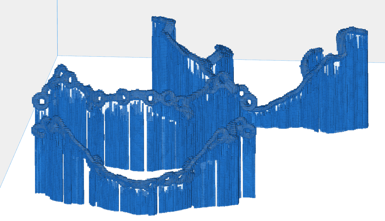
Visualization of Step 2: Voxelization of Three Different Part Orientations
Modeling is a powerful tool to minimize failed print sessions. It provides valuable information on how to place (or not place) support or critical segments. Let's look at the modeling workflow.
- Getting CAD geometry of the part and support configurations.
- Voxelization of part geometry and verification of supporting structures in boundary conditions.
- Modeling layer-by-layer construction using the method of intrinsic stresses.
- Interpolation of voxel results to the original CAD geometry.
We decided to focus on the speed of modeling, so the voxelization of parts has a rather large grain. Our goal was not to simulate the exact distortion of any configuration, but to determine which of the configurations is subject to the least qualitative distortion. In just three minutes, we simulated an entire voxelized platform.
Evaluation of the results
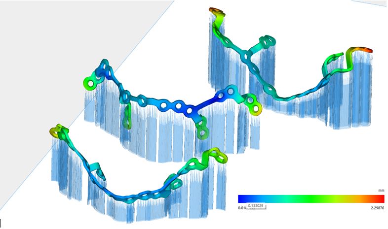
Deformation modeling after separation of support.
To simulate and view the results, the Magics Simulation software module was used . Selective loading of the most relevant modeling data in Magics has improved the selection process for optimal orientation. The figure below shows three different configurations of part supports (transparent) and simulated implant deformations after separation of support. As you can see in the image, the configuration of supporting the part with the least deformation is in the middle. It does not contain red and yellow zones.
To confirm the simulation results, we compared the deviations in the design of deformed parts from the original CAD geometry for the simulated and printed parts. As can be seen below, the simulated and printed designs have the same deviation pattern. The upper configuration contains the largest geometric deviation from the original CAD geometry, and the average contains the smallest deviation.

Comparison of simulated strains and printed structures with original geometry
Finding the smallest strain
In this example, we used finite element modeling to quickly predict global deformations of three different configurations of cranial-maxillofacial implant support parts. Rough voxelization made it possible to quickly model and obtain data on the qualitative tendencies of deformation. Actual test samples printed on a 3D printer confirmed that of the three configurations proposed in this study, the average one underwent the least deformation after removing the supporting structure .
Thus, the second model also confirms that the predictive ability of modeling is a valuable tool for additive manufacturing engineers. Using the Magics simulation module, they can evaluate their designs before the manufacturing stage, which allows them to find the optimal orientation of the parts and support configuration.
Please note that Materialize Magics is not medical software. The user is responsible for approving the production process and the product for use as a medical device. Materialize orthognathic implants are protected by patents EP 2398411, US 8,784,456, US9,247,972, US 9,339,279. Other patents pending.
* The method of internal stresses (ISM) is a modeling procedure adapted on the basis of welding simulation to predict residual stresses and deformation in the process of additive production. ISM simplifies the complex, labor-intensive thermomechanical process of additive manufacturing to simple quasistatic analysis, allowing you to quickly and accurately model complex additive components.
Translation from English. The original article is here .