Hacking an HP color cartridge: turning it into a handheld printer
- Transfer
Introduction
Ever since youth, when we had the old DeskJet, I was interested in inkjet printer cartridges. These cartridges seemed very interesting and as soon as they ran out of ink, I immediately took them to myself. At that time, I could do nothing with them, except to disassemble and get my hands dirty ... Although I knew that there was some kind of complex electronics inside, but when the contacts touched the battery, nothing interesting happened, and my knowledge of electronics for more not enough.
A little later, when I became a student, I managed to get an old inkjet printer. At that time, I myself used a laser printer, so I was not very interested in it, but it was interesting to examine the cartridges and try to reverse engineer them. I actually wrote an articleabout managing these cartridges, and although they worked quite well, there were also drawbacks: I still could not figure out the exact order of the nozzles, the cartridge was only monochrome (printed with a magenta), and also quite old, and therefore the resolution turned out to be quite low.
Recently, my girlfriend started painting, so this was a good excuse for returning to ink cartridges in the hope that I would be able to draw something on canvas. This time I was lucky: I managed to find a way to bind all the nozzles to the correct signals. In addition, today printer cartridges control more nozzles using fewer signals, which simplifies cartridge management and increases the surface that can be covered in one pass.
I finally managed to get control of the tri-color cartridge and print in full color!
If you want to go with me from the heap of printers to complete control of the printer cartridge, I made a report about it at Hackaday Supercon 2018. The video recording of the speech is added below. If you are interested in the details of reverse engineering, then check it out. In the article, I will talk about the technical details of the electronics I created, as well as the specific details of managing the cartridge so that you yourself can draw the Nyancat using ESP32 or another microcontroller.
Presentation Attachment
If you haven’t watched the video, here is a brief summary: I took apart the color cartridge for the HP1112 printer (in China it is an HP 803 cartridge, but the article number depends on the region), took pictures of the crystal and tried to figure out how it works. When I was unable to find out a lot, I began to read the signals transmitted between the printer and the cartridge, figured out which signals to send in order for the cartridge to obey my orders, and then printed Nyancat and other funny things.
The signal timing part of the study was mainly a trial and error process. I can only guess what kind of connection exists between the signals, so it was quite difficult to figure out the order between the edges and which signals can be delayed and which should be transmitted on time. I studied a silicon cartridge for this information. It turned out that I actually managed to get it by putting the cartridge under the microscope, but not at all as I expected.
Before speaking at Supercon, I studied color cartridges because they seemed to me the most interesting. After returning from Supercon, I wanted to reverse engineer the black cartridge: its print head is larger than that of the color cartridge, so I could print more at a time. It is probably not that difficult to add support for this cartridge either: the pin arrangement seems the same, and I knew that the protocol would most likely be similar, because I had already tried connecting the black cartridge to my hardware. Even though the software was transmitting color images, it still managed to print something.
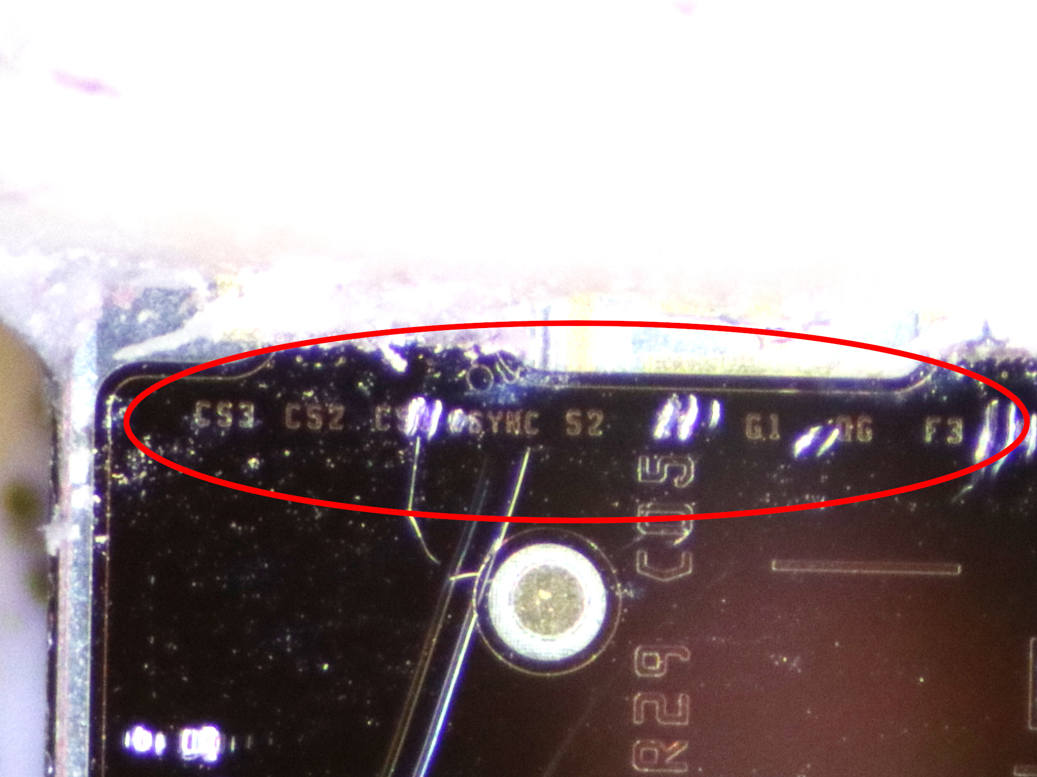
Here's what I did with the color cartridge: I stuck it under the microscope, removed the silicone coating from the contacts, and prepared to combine several shots into one large image. However, the black cartridge differed from the color one in that there were more inscriptions on its metal plate with nozzles: under the silicone coating there were hidden signal names for all contacts!
(By the way, if you want to see full microscope pictures in all 40-megapixel grandeur, then here is the shield and silicon of the color cartridge! Admire the complexity of the nozzles and the crystal image of the black cartridge!)
Although it may seem that this is not so much, in a sea of unmarked printed circuit boards, chips without reference materials and articles that do not lead anywhere, the names of several signals are a real find. On a hunch, I drove certain names of signals with the name “Hewlett Packard” into Google Patents and discovered a specific patent (and another, olderwhich the first refers to) with a clear description of the technologies and signals used in the cartridges. That would save me so much time when I struggled with cartridge timings ... oh well. I can sincerely say that this hint was very difficult to find: the signals were not only covered with silicone film, but also turned out to be tiny: the letters are only 30 micrometers in size, and this is less than the thickness of a human hair.
The patent describes the internal operation of the cartridge and is worth reading (if you can figure out the legal jargon used there) just to understand how strange logic HP sometimes uses to control all nozzles. The patent itself is useful, but not enough to control the cartridge; at least the bulk of the reverse engineering work that I undertook would still be necessary, even if I had this patent.
Here and below I will use the names of the signals and contacts used in the patent. Please note that in the code my own names of signals can still be found; I will include a translation table along with the documentation.
Data encoding

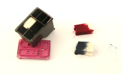
So, here is what the cartridges under study look like. At a superficial glance, these are fairly simple devices: inside, they almost entirely consist of an ink-soaked sponge. In the case of the cartridge that came with the printer, there is very little ink: only half the space in the cartridge is occupied by the sponges, and the sponges themselves are also half empty:
On the side there are 16 contacts going from the bottom where the print head is located. As you could see in the microscope, there are approximately 336 nozzles in the print head of the black cartridge, and 612 nozzles in the color cartridge. The nozzles are arranged in vertical rows on the print head, and each nozzle can be controlled electronically so that it shoots a tiny drop of ink down toward the side of the paper inserted into the printer. By moving the head vertically, the printer can print a “strip” or any other image; in the case of a black cartridge, this strip is approximately 15 mm long and 8 mm for a color cartridge.
Obviously, nozzles can be controlled using contacts. According to the tiny print head inscriptions, the contacts contain the following signals:

Since there are only 16 contacts, there must be some kind of multiplexing scheme for controlling all nozzles. The patent explains how it works: nozzle control is divided into 14 separate groups. These groups are triggered sequentially: first they receive their data and group 1 is triggered, then group 2, and so on. Each group controls a maximum of 24 nozzles, and data for them is transmitted via three data buses. In the case of a color cartridge, the data in the three buses corresponds to the colors: D1 is the yellow data, D2 is the magenta data, and D3 controls the cyan nozzles.
In the patent, work is described in detail using one data bus as an example. This figure from the patent shows the signals used:

The data bus contains eight bytes, 0-7. Even bytes are controlled by the trailing edge of DCLK, odd bytes are controlled by the trailing edges of S1-S4. Nozzles whose data is controlled by the first four bytes can be turned on by supplying power via the power bus F3; nozzles associated with the last four bits are turned on by the F5 bus.
I have no idea why HP decided to use such a complex circuit to manage nozzle data. We can say that something obvious, like a shift register, would have worked quite normally here. I understand that HP uses its patents as a weapon against cartridge refilling companies; perhaps someone has already patented a simpler solution, and they had to come up with this more complex solution to be unique.
On this graph, made by me on a logic analyzer, it is not difficult to find the signals described in the patent:
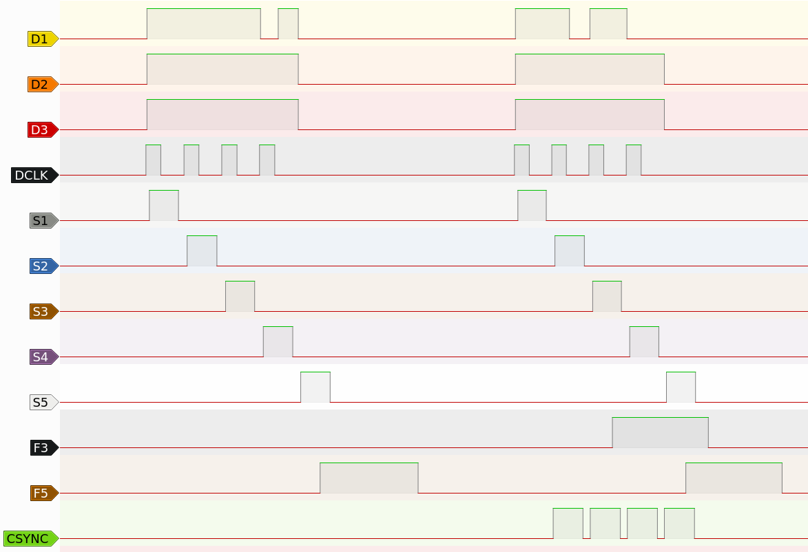
In addition to controlling the nozzles, the cartridge also needs a signal (csync) to go to the next group of nozzles or to reset and return to the first group. It can be seen in the image from the logical analyzer: it shows the penultimate and last groups of 14, and the csync signal has a recognizable shape in the last group; he performs a “reset” of the cartridge so that the first group receives data next. This signal can also be used to bypass groups of nozzles in the reverse order; this is useful when the print head moves from left to right, and from right to left. Although the second patent describes how this works, I decided to simply encode the transition to the next group and reset the signals shown in my images by the csync line.
Note that all this happens at a fairly high speed; the delay between the two leading edges of the DCLK signal is approximately 0.4 μs, and the distance between the groups is approximately 4 μs.
Now we know that each bit in these three data buses of 14 bytes contains an operation command for one nozzle. If the bit is 0, then the corresponding nozzle is triggered; if equal to 1, then the nozzle does not work. What we don’t know is the correspondence between bits and nozzles. If you watched the presentation, then you know how I managed to figure it out: I printed out a known pattern on a working printer, intercepting the signals using a logic analyzer, and then I figured out what the order of the signals should be in order to decode the signals back to the original image
.
Unfortunately, the matching of bits to nozzles seems fairly constant, but not completely logical. It seems that this is mainly due to the need to physically move the nozzles simultaneously at a sufficient distance (to avoid overheating or the occurrence of a local vacuum in the ink tank). In addition, I also found that the ease of routing signals in a cartridge can make bit and nozzle matching pretty confusing. In my firmware, I simply implemented this mapping as a set of lookup tables.
Electronics
Now that we know how signals work, we can control the printer cartridge with a simple microcontroller, right? Well, not right away. The printer cartridge does not use simple 5 V or 3.3 V logic. Data buses are controlled by 16 V or 9 V buses. Power buses are also controlled by 16 V and in fact, depending on the number of triggered nozzles, they can be pulled up to the power supply current . We need to perform a level conversion.
As the level converter, I chose the MC14504. This is an old unidirectional hexadecimal level conversion chip that can increase the voltage to 18 V. Although this chip also works, looking back, I can say that this was not the best choice: it can only output a few mA and has a rather large propagation delay. I think it provides a delay of some output signals depending on the cartridge and the load applied to the chip outputs. I have at least one cartridge that needs a little timing adjustment for the signals to work, and I think that is the reason. Unfortunately, ready-made 16V level converters are not so accessible today, so I can not replace it with something better. However, this classic chip with a little adjustment is quite enough.
With power buses, things are a little more complicated. In addition to the fact that these contacts take a large share of the current, they are also directly connected to the resistors of the included nozzles: if for some reason the power is supplied for too long, these tiny resistors will burn out and the nozzle will completely fail. In addition, this “too long” is quite simple to achieve: it is enough to turn on the nozzles for only a few microseconds, and if you supply power for only a millisecond, they will simply evaporate, completely breaking the nozzle. To prevent this from happening due to a software bug or a bad connection, I added hardware logic that ensures that the pulse is limited to a small multiple of 10 μs.

In the first prototype, I left several level converters and did not know how the software would work, so I solved the problem with a real single-cycle multivibrator. In this circuit, two multivibrators are used in the 74HC123, generating pulses, the width of which is set by the combination of R / C connected to the RCExt pin. The resulting pulse is generated only with an increasing input signal, so a constantly high signal will not lead to anything other than a precisely defined, but spurious output pulse. After that, the MC14504 channel is used as a level converter to raise the voltage to +16 V, and the P-channel MOS transistor provides the necessary current.

On the second printed circuit board, I realized that if I change the logic of the power contacts so that they do not use two channels of the level shift circuit, then only two MC14504 chips will be enough. Now I have good enough programmatic control over the pulse width, but I still want to have protection against a constantly high input contact signal. Here is the diagram I came to. It works like this: in the normal state with a low signal PWRB_IN, the capacitor C28 is empty, because any voltage in it flows slowly along R20 and R21: the gate of the transistor Q4 is high, and PWRB_OUT is disconnected from the 16 V power bus. As soon as high in PWRB_IN appears high signal, Q6 ground one end of C28; since the voltage across it is 0 V, initially this also pulls down its other side, which is connected to the gate Q4. Pulling the Q4 shutter down makes it conductive, and this allows current to flow from +16 V to PWRB_OUT. In the normal state, PWRB_IN switches back to the low state quickly enough, closing the gate Q4 and interrupting the current. However, while PWRB_IN is low, the C28 is slowly charging: one side is grounded to Q6, and the other is connected to 16 V via R21 and R31. When the capacitor is sufficiently charged, Q4 “sees” a high level on its gate and switches off the current in PWRB_OUT, even if PWRB_IN is still in a high signal state. This mechanism ensures that PWRB_OUT only supplies power for a limited amount of time. However, while PWRB_IN is low, the C28 is slowly charging: one side is grounded to Q6, and the other is connected to 16 V via R21 and R31. When the capacitor is sufficiently charged, Q4 “sees” a high level on its gate and switches off the current in PWRB_OUT, even if PWRB_IN is still in a high signal state. This mechanism ensures that PWRB_OUT only supplies power for a limited amount of time. However, while PWRB_IN is low, the C28 is slowly charging: one side is grounded to Q6, and the other is connected to 16 V via R21 and R31. When the capacitor is sufficiently charged, Q4 “sees” a high level on its gate and switches off the current in PWRB_OUT, even if PWRB_IN is still in a high signal state. This mechanism ensures that PWRB_OUT only supplies power for a limited amount of time.
The circuit also has a small resistor connected in series with the 16 V power bus (R31), as well as a small capacitor connected in parallel with the output signal (C15). They are needed to "relieve the voltage" of the power signal: without them, a sharp on and off Q4 will induce a bunch of electromagnetic interference, distorting the signals transmitted to the cartridge.
Other than this logic, nothing more is needed. Obviously, +9 V and +16 V level converters are needed. The +9 V power supply should be quite modest: I did not notice that these buses generally used more than a few mA. Since it feeds the nozzle resistors, the 16 V source should be a little stronger: I made it so that mine could provide at least 400 mA continuously, and also added quite a lot of decoupling capacitance.
Finally, the most important burden of image processing and signal generation rests with the microcontroller. For this purpose I chose ESP32, mainly because I took a few pieces from work, but also because it has a rather powerful I2S controller that uses a very convenient parallel mode: in fact, we can just set the clock frequency, specify the memory area for the I2S controller and it will output these bytes in parallel. Thanks to this, it is ideal for generating the necessary control signals; The fact that it has two powerful 240 MHz cores also helps in image processing.
Prototype
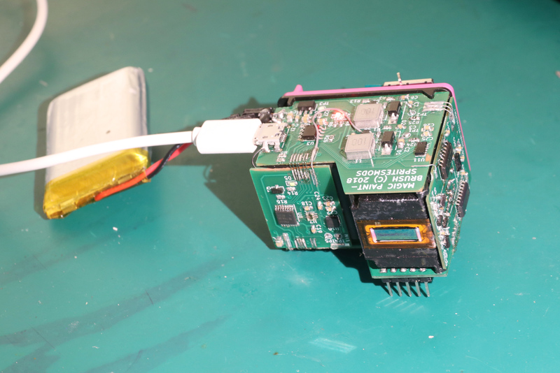
Of course, several converters and MOS transistors alone cannot become a working printer cartridge controller. Therefore, I created a separate device, conceived as a platform for experimenting with a cartridge and its capabilities. It has an ESP32 module, the logic needed to control the cartridge, and several power supplies for working from a lithium-ion cell. It is also equipped with several sensors designed to compensate for imperfect movements of a person’s hands, as well as buttons and a display that provides feedback on printed images. Let's take a look at the components, perhaps for someone it will become an inspiration for cartridge hacking:

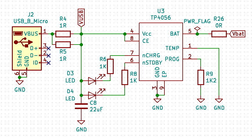
Let's start with the power source. Power is supplied from a lithium-ion cell and converted to 3.3 V, 16 V and 9 V. A voltage of 3.3 V is required for sensors and ESP32; it is generated using a simple LD78 regulator HT7833. Voltages of 9 V and 16 V are generated by two boost converters based on the boost converter chip XR2203. Please note that a 16 V power supply must work much harder than a 9 V power supply; the cartridge consumes from 9 V only a few milliamps. Two boost converters were created on the same chip simply because it was enough for me to buy one type of component for both.
Since the entire device is powered by a lithium-ion cell, we need to somehow charge it. I have little space left, so I added a TP4056-based lithium-ion battery charger so that I could recharge the battery from any USB power source.
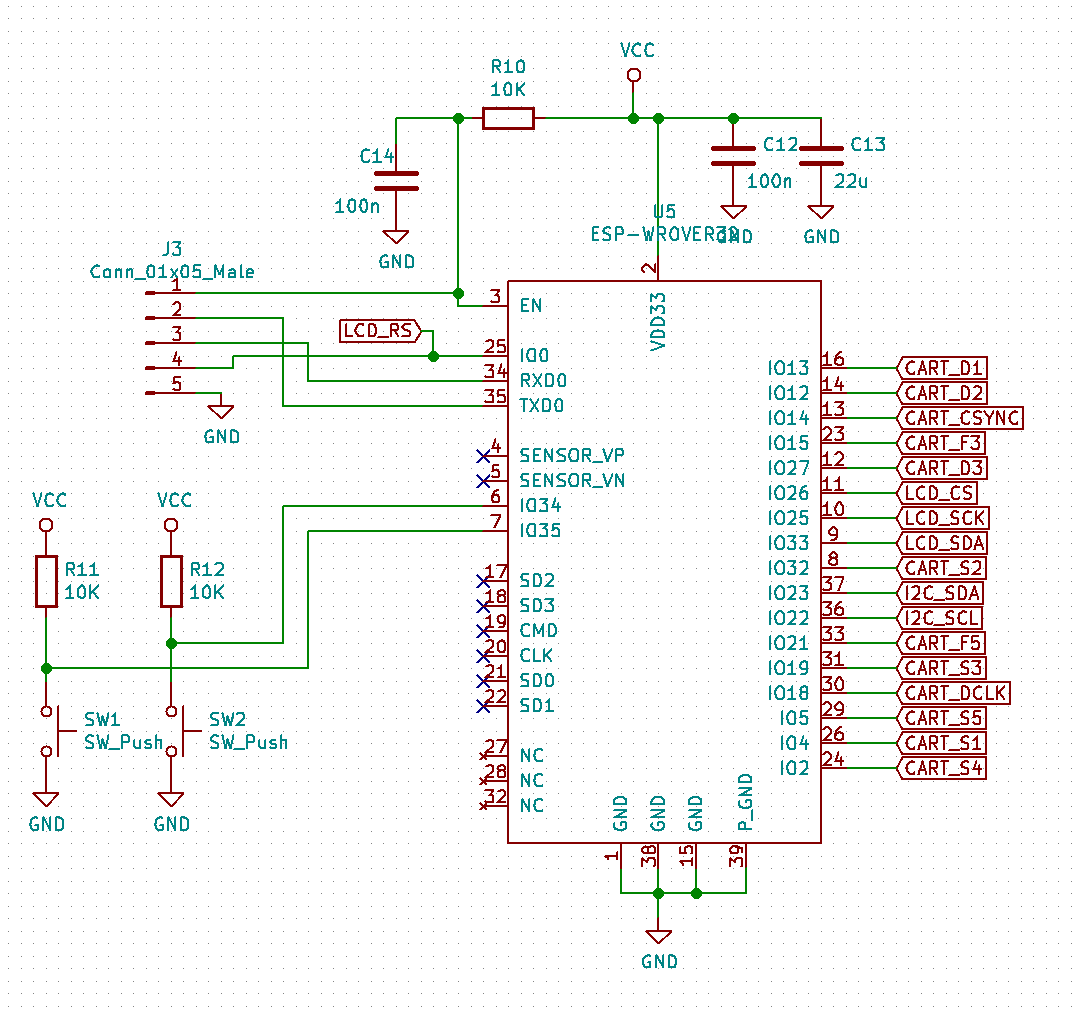
The intelligence of the device is provided by the ESP-Wrover32 module. I used the option with 8 MiB of flash memory and 8 MiB of RAM SPI; quite enough to perform complex image processing. The module also has a 5-pin connector that allows you to program and debug the firmware, as well as two buttons that can be used to select options and start rendering when the firmware is running.

Selected options are displayed on a small 160x80 small color LCD screen. The screen has an SPI connection and can be directly controlled by one of the peripheral SPI connectors available in the ESP32.

This is the cartridge interface. As stated above, it is not particularly complicated. The level of all signals is converted by the MC14504 pair, one for 9 V signals and one for 16 V. signals. Also on the diagram is a level / protection shift circuit controlling dual power buses.

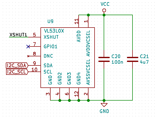
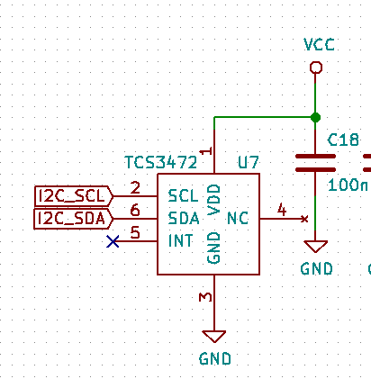
Here are three types of sensors I used. All of them are connected using one I2C bus, that is, in ESP32 they occupy only two GPIOs. This is a block of inertial sensors MPU9250 (accelerometer, gyroscope and digital compass) for measuring motion, three laser distance sensors VL53L0X (only one is shown), directed up, left and right. The idea is that by combining this information, it is theoretically possible to determine the absolute position of the cartridge. This is useful, for example, when drawing large images with a free hand movement. The latter is the TCS3472 color sensor. The color sensor is located next to the white LED; it can be used to “copy” the color from the subject or to compensate for the color of the medium on which we print.
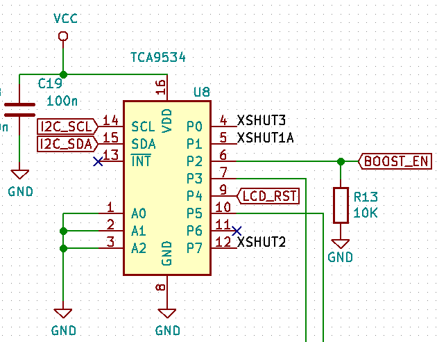
Since I needed additional GPIOs, I connected a GPIO expander to the bus. It controls the reset buses for the three distance sensors, the reset bus for the LCD screen, the inclusion of a boost converter and two MOS transistors (not shown) that control the white LED used to illuminate the target for the color sensor, and the backlight of the LCD screen. Distance sensors need a separate reset bus, because they will turn on at the same I2C address. However, they do have a command that changes the I2C address after it is turned on. By turning them on and moving them one by one to different I2C addresses, I can control all three on the same I2C bus.
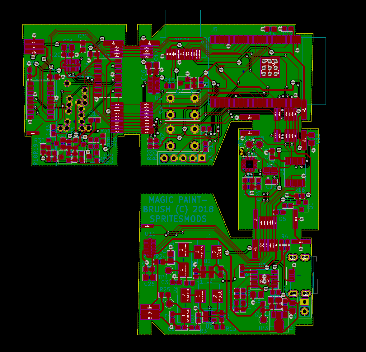
Here is the circuit board that I designed based on the circuit. It has a strange shape, because it must be divided into four separate boards and "surround" the printer cartridge. They are connected electrically and physically; the advantage of this is that the manufacturers of printed circuit boards do not consider such a circuit to be four separate boards and you only need to pay for one.

Another advantage is that I can assemble the board as one element, and then test it when all the components are on the same plane. This allows me not to carefully balance the assembled device during debugging. A small note: VL53L0X sensors use an infrared laser beam; It seems that it is strong enough to break through the filter of protection against infrared radiation in my “mirror” and appears in the frame as small purple spots of light.

And what will be the final result after assembly. Note that when the boards were separated, the connections between them were broken. The boards have small soldering pads to which you can solder a small piece of wire and bend it. Obviously, for the production level, you will need to use technologies like FPC PCB or flex-rigid PCB, but for a cheap prototype this will work.
If you want to use this prototype for reference or experiment with it, you can download the KiCad project files (there are also pdf and gerber diagrams in the same place) and assemble it yourself, or use its subsystems.
Since this is a prototype, the software is rather ... heterogeneous. I will give a link to the repository in which it was developed, but keep in mind that this is a cast of almost the entire development cycle, so it contains everything in order, from the signal recordings of the logic analyzer to the printed Nyancat and Mona Lisa. Unfortunately, that's why the code is almost undocumented chaos with half-completed paths and remnants of the old code. If you still want to learn it, you can clone this URL in git .
However, if you are more interested in software that can easily control the printer cartridge using ESP32 (and contains useful procedures for controlling it through another microcontroller), then continue reading.
Minimum working version
To make it easier for other craftsmen to use printer cartridges in their own projects, I also created a minimal working version of the driver. It lacks support for all peripherals and hacks from the prototype code, but the architecture is cleaned up and therefore can become a solid foundation for further development. The driver has a simple example of a program that prints when the HELLO! Button is pressed color or black cartridge.
I did not create specialized equipment for it, but in fact you can reuse the hardware from the previous section: just take a power supply , ESP32
and level convertersand apply them in your own scheme. You can also fully use the prototype described in the previous section: it is enough to simply provide a constant high signal BOOST_EN so that the 9 V / 16 V boost converters are always on. (This way I debugged the code.)
The code itself can be found on Github , it is structured standardly for the ESP-IDF project. The main driver code is in components / printcart ; code reading button and decide when to turn on the nozzle, as well as the initialization code contained in the main / main.c . In the example, nozzle data is read from the embedded rgb image.
The system has the following architecture: printcart_i2s.ccontains a simple driver for parallel mode of the I2S peripheral connectors of the ESP32 controller. It selects two buffers and transfers from the buffers 16-bit words with a frequency of 3.3 MHz to GPIO contacts (maximum 16 contacts). (Here, these GPIO pins are connected to the level converters that control the cartridge.) Each time the buffer is empty, the driver executes an event handler to fill the buffer.
The event handler is located in printcart_buffer_filler.c . It receives nozzle data from the nozzle data queue and passes it to a function in printcart_genwaveform.c , which by template converts these nozzle data into signals. The template depends on the type of cartridge (color or black), and you can change it by loading tools / waveform_editor.html into the browser .
On the other hand, the nozzle data queue is the loop procedure in main.c. It waits for a button to be pressed, and when pressed, it generates nozzle data by parsing a simple image file converted into raw rgb data and embedded into a stitched binary file, scanning the data from left to right. Thanks to this, you can press the button, sweeping the cartridge over the paper, and print the contents of the image as an ink strip.
The end result looks something like this:

It is very noticeable here that the black cartridge prints about twice as much in height as the color (0.7 cm and 1.5 cm), so if you do not need color and you need good visibility, then it is better to choose a black cartridge. It is also worth noting that in main.c there is define that switches between two cartridges; code can work with both. It’s not entirely clear why there are blurry lines in the black image: maybe there is an error in my signal, or maybe the cartridge is a little tired of testing. Be that as it may, the printed data is beautiful and well recognizable.
Finally
The reverse engineering of these printer cartridges was a long adventure, but in the end my work was fruitful; although there are a few puzzles left (for example: what does the ID contact do?), I think I’ve understood the riddles of the signals used in the cartridge well. I hope that by publishing the code and diagrams of this project, I will add the use of printer cartridges to the toolkit of craftsmen, hackers and creators. I can’t wait to see interesting usage examples that the community will come up with. If you manage to do something interesting with my work, be sure to send me a message .
As for my intention to create art ... umm ... can this be called that?
