Making Game Boy Game Part 2
- Transfer
A few weeks ago, I decided to work on a Game Boy game, the creation of which gave me great pleasure. Her working title is “Aqua and Ashes”. The game has open source and is available on GitHub . The previous part of the article is here .
Fantastic sprites and where they live
In the last part, I finished rendering several sprites to the screen. This was done in a very arbitrary and chaotic way. In fact, I had to specify in the code what and where I want to display. This made the creation of animation almost impossible, spent a lot of CPU time and complicated code maintenance. I needed a better way.
Specifically, I needed a system in which I could simply iterate through the animation number, frame number, and timer for each individual animation. If I needed to change the animation, I would just change the animation and reset the frame counter. The animation procedure performed in each frame should simply select the appropriate sprites to display and throw them onto the screen without any effort on my part.
And as it turned out, this problem is almost solved. What I’m looking for is called sprite mappings . Sprite maps are data structures that (roughly speaking) contain a list of sprites. Each sprite card contains all the sprites for rendering a single object. Also associated with them are animation maps (animation mappings) , which are lists of sprite maps with information on how to loop.
It's pretty funny that back in May I added an animation map editor to the already ready sprite map editor of 16-bit Sonic games. (It is here , you can study) It is not yet complete, because it is rather rough, painfully slow and inconvenient to use. But from a technical point of view, it works. And me it seems that he is pretty cool ... (One of the reasons for the roughness was that I literally worked with the JavaScript framework for the first time.) Sonic is an old game, so it’s perfect as a foundation for my new-old game.
Sonic 2 card format
I intended to use the editor in Sonic 2, because I wanted to create a hack for Genesis. Sonic 1 and 3K are basically almost the same, but in order not to complicate things, I will limit myself to the story about the second part.
First, let's look at the sprite maps. Here's a pretty typical taile sprite, part of the blinking animation.

The Genesis console creates sprites a little differently. A Genesis Tile (most programmers call it a “pattern”) is 8x8 in size, just like on a Game Boy. A sprite consists of a 4x4 rectangle in size, in many respects similar to the 8x16 sprites mode on the Game Boy, but more flexible. The trick here is that these tiles should be in memory next to each other. The developers of Sonic 2 wanted to reuse as many tiles as possible for the frame of the blinking Tails from the frame of the standing Tails. Therefore Teylz is divided into 2 hardware sprites consisting of 3x2 tiles - one for the head, the other for the body. They are shown in the figure below.
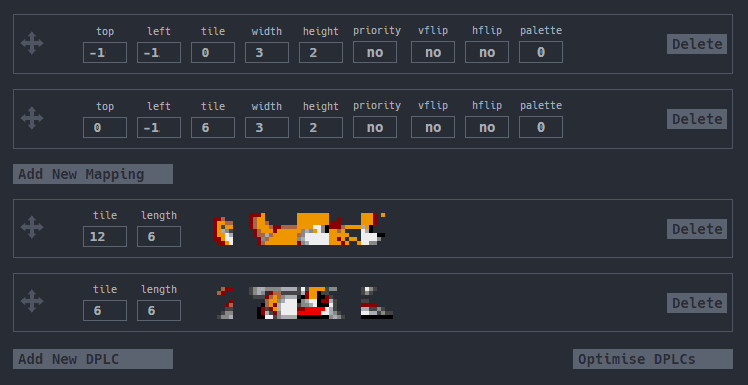
The upper part of this dialog box is the attribute of hardware sprites. It contains their position relative to the starting point (negative numbers are cut off; in fact, it is -16 and -12 for the first sprite and -12 for the second), the initial tile used in VRAM, the width and height of the sprite, as well as various status bits for mirror image sprite and palette.
The bottom part shows the tiles as they are loaded from ROM to VRAM. There is not enough space to store all Tail sprites in VRAM, so the necessary tiles have to be copied to memory in each frame. They are called Dynamic Pattern Load Cues . However, for now we can skip them, because they are almost independent of sprite cards, and therefore they can easily be added later.

As for the animation, everything is a little simpler. Sonic's animation map is a list of sprite maps with two pieces of metadata — a speed value and an action performed after the animation is complete. The three most frequently used actions are: cycle through all frames, cycle through the last N frames, or transition to a completely different animation (for example, when moving from an animation of a standing Sonic to an animation of his impatient foot-stomping). There are also a couple of commands that set the internal flags in the memory of objects, but not many objects use them. (Now it occurred to me that you can set a bit in the object's RAM value when looping the animation. This will be useful for sound effects and other things.)
If you look at the disassembled Sonic 1 code(Sonic 2 code is too big to link to it), then you can see that the link to the animation is not made by any ID. Each object is given a list of animations, and the animation index is stored in memory. To render a specific animation, the game takes an index, looks for it in the list of animations, and then renders it. This makes the job a bit easier because you don’t need to scan the animations to find the one you want.
We clean the soup from the structures
Let's look at the types of cards:
- Sprite cards: a list of sprites consisting of an initial tile, number of tiles, position, state of reflection (sprite is mirrored or not) and a palette.
- DPLC: a list of tiles from ROM that need to be loaded into VRAM. Each element in the DPLC consists of an initial tile and a length; each element is placed in VRAM after the latter.
- Animation maps: a list of animations consisting of a list of sprite maps, speed values, and cycle actions.
- List of animations: a list of pointers to the action of each animation.
Considering that we work with Game Boy, some simplifications can be made. We know that there will always be two tiles in the 8x16 sprite cards. However, everything else needs to be saved. For now, we can completely abandon DPLC and just keep everything in VRAM. This is a temporary solution, but, as I said, this problem will be easy to solve. Finally, we can discard the speed value if we assume that each animation works at the same speed.
Let's start to understand how to implement a similar system in my game.
Check with the commit 2e5e5b7 !
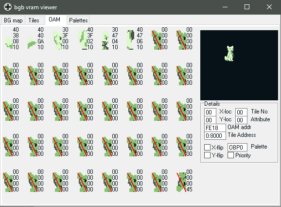
Let's start with the sprite cards. Each element in the map should mirror the OAM (Object Attribute Memory - Sprite VRAM) and thus a simple loop and memcpy will be enough to display the object. I recall thatelement in OAM consists of Y, X, initial tile and attribute byte . I just need to create a list of them. Using the assembler pseudo-operator EQU, I prepared an attribute byte in advance so that I had a readable name for each possible combination of attributes. (You may notice that in the previous commit I replaced Y / X with a tile in the maps. This happened because I didn’t read the OAM specifications carefully. I also added a sprite counter to know how long the loop would perform.)
You will notice that the body and the tail polar foxes are stored separately. If they were kept together, then there would be a largeredundancy, because each animation would have to be duplicated for each tail state. And the scale of redundancy would quickly increase. In Sonic 2, the same problem arose with Tails. It was decided there by making Tails tails a separate object with its own state of animation and a timer. I do not want to do this, because I do not want to solve the problem of maintaining the correct position of the tail relative to the fox.
I solved the problem through animation maps. If you look at my (only) animation map, then there are three pieces of metadata in it. It indicates the number of animation cards, so I know when they will end. (Sonic checks if the next animation is invalid, similar to the concept of the zero byte in lines C. The solution from Sonic frees the register, but adds a comparison that would work against me.) Of course, there is also a loop action. (I turned the Sonic 2-byte scheme into a 1-byte number, in which bit 7 is the mode bit.) But I also have the number of sprite cards, and in Sonic it was not. Having several sprite cards on one frame of animation allows me to reuse animations in several animations, which, I think, will save a lot of precious space. You may also notice that the animations are duplicated for each direction. This is done because the maps for each direction are different and must be added.
Dance with registers
Check out this file in commit 1713848.
Let's start by drawing a single sprite on the screen. So, I confess, I lied. Let me remind you that we can not write to the screen outside VBlank. And this whole process is too long to fit into VBlank. Therefore, we need to write the memory area we will allocate for the DMA. In the end, it does not change anything, it is important to write to the right place.
Let's start counting registers. The GBZ80 processor has 6 registers, from A to E, H and L. H and L are special registers, so they are well suited for iterating through memory. (Since they are used together, they are called HL.) In one opcode, I can write to the memory address contained in HL and add one to it. It's hard to handle this. You can use it either as a source or as a destination. I used it as an address, and the combination of registers BC as a source, because it was most convenient. We only have A, D and E. I need the register A for mathematical operations and the like. What can DE be used for? I use D as the loop counter, and E as the workspace. And on this registers have ended.
Let's say we have 4 sprites. Register D (loop counter), we set the value to 4, register HL (addressee) - the address of the buffer OAM, and BC (source) - a place in the ROM, which stores our cards. Now I would like to call memcpy. However, there is a small problem. Remember the X and Y coordinates? They are indicated relative to the starting point, the center of the object is used for collisions and the like. If we recorded them as they were, then each object would be displayed in the upper left corner of the screen. It does not suit us. To fix this, we need to add the X and Y coordinates of the object to the X and Y sprite.
Brief note: I am talking about “objects”, but did not explain this concept to you. An object is simply a set of attributes associated with an item in a game. Attributes are position, speed, direction. item description, etc. I’m talking about this because I need to pull out the X and Y data from these objects. This will require a third set of registers pointing to the place in the RAM of the objects where the coordinates are. And then we need to store X and Y somewhere. The same applies to the direction, because it helps us to determine which way the sprites are looking. In addition, we need to render all the objects, so they also need a loop counter. And we haven't gotten to the animations yet! Everything gets out of control very quickly ...
Revision of the decision
So, I'm running too far ahead. Let's go back and think about each piece of data that I need to track, and where to write it.
To begin, let's divide this into “stages.” Each stage should only receive data for the next, with the exception of the last, which performs the copy.
- Object (cycle) - determines whether the object should be rendered, and renders it.
- List of animations - determines which animation to display. Also gets the attributes of the object.
- Animation (loop) - determines which list of maps to use, and renders each map from it.
- Map (cycle) - iteratively passes through each sprite in the list of sprites
- Sprite - copies sprite attributes to OAM buffer
For each of the stages, I listed the variables they need, the roles they play and the places to store them. This table looks like this.
| Description | The size | Stage | Using | From where | A place | Where |
|---|---|---|---|---|---|---|
| OAM buffer | 2 | Sprite | Pointer | HL | HL | |
| Source maps | 2 | Sprite | Pointer | BC | BC | |
| Current byte | one | Sprite | Workspace | Source maps | E | |
| X | one | Sprite | Variable | Hiram | A | |
| Y | one | Sprite | Variable | Hiram | A | |
| Start of the animation map | 2 | Sprite map | Pointer | Stack3 | DE | |
| Source maps | 2 | Sprite map | Pointer | [DE] | BC | |
| Remaining sprites | one | Sprite map | Scratch | Source maps | D | |
| OAM buffer | one | Sprite map | Pointer | HL | HL | Stack1 |
| Start of the animation map | 2 | Animation | Workspace | BC / Stack3 | BC | Stack3 |
| Remaining cards | one | Animation | Workspace | Start of animation | Hiram | |
| Total number of cards | one | Animania | Variable | Start of animation | Hiram | |
| Direction of the object | one | Animation | Variable | Hiram | Hiram | |
| Cards per frame | one | Animation | Variable | Start of animation | NOT USED!!! | |
| Frame number | one | Animation | Variable | Hiram | A | |
| Map pointer | 2 | Animation | Pointer | AnimStart + Dir * TMC + MpF * F # | BC | DE |
| OAM buffer | 2 | Animation | Pointer | Stack1 | HL | |
| Start animation table | 2 | List of animations | Workspace | Set hard | DE | |
| Object source | 2 | List of animations | Pointer | HL | HL | Stack2 |
| Frame number | one | List of animations | Variable | Object source | Hiram | |
| Animation number | one | List of animations | Workspace | Object source | A | |
| X object | one | List of objects | Variable | Object source | Hiram | |
| Y object | one | List of animations | Variable | Object source | Hiram | |
| Direction of the object | one | List of animations | Variable | Obj src | Hiram | |
| Start of the animation map | 2 | List of animations | Pointer | [Anim Table + Anim #] | BC | |
| OAM buffer | 2 | List of animations | Pointer | DE | Stack1 | |
| Object source | 2 | Object cycle | Pointer | Set hard / stack2 | HL | |
| Remaining objects | one | Object cycle | Variable | Is calculated | B | |
| Active bit field of the object | one | Object cycle | Variable | Is calculated | C | |
| OAM buffer | 2 | Object cycle | Pointer | Set hard | DE | |
Yes, very confusing. To be perfectly honest, I made this table only for the post, in order to explain more clearly, but it has already begun to be useful. I will try to explain it. We will start from the end and we will get to the very beginning. You will see every piece of data that I start with: the source of the object, the OAM buffer, and the pre-calculated loop variables. In each cycle, we begin with this and only this, except that the source of the object is updated in each cycle.
For each object that we render, it is necessary to determine the displayed animation. While we are doing this, you can also save the attributes X, Y, Frame # and Direction, before incrementing the object pointer to the next object and saving them to the stack, to take back on exit. We use the animation number in conjunction with the hard-coded animation table in the code to determine where the animation map begins. (I simplify here, implying that each object has the same animation table. This limits me to 256 animations per game, but I can hardly surpass this value.) We can also write the OAM buffer to save several registers.
After extracting the animation map, we need to find where the list of sprite maps is for the given frame and direction, as well as how many maps we need to render. You may notice that the map variable per frame is not used. It happened because I didn’t think and set a constant value of 2. I need to fix this. We also need to extract the OAM buffer from the stack. You may also notice a complete lack of cycle control. It is executed in a separate, much simpler sub-procedure, which allows you to get rid of juggling registers.
After that, everything becomes quite simple. The map is a bunch of sprites, so we loop around them and draw them with the saved X and Y coordinates. However, we again save the OAM pointer to the end of the sprite list so that the next map starts where we finished.
What was the final result of all this? Exactly the same as before: waving a tail in the dark by a polar fox. But adding new animations or sprites is now much easier. In the next part I will talk about complex backgrounds and parallax scrolling.

Part 4. Parallax Background
Let me remind you that at the current stage we have animated sprites on a solid black background. If I do not plan to make an arcade game of the 70s, then this is clearly not enough. I need some kind of background image.
In the first part, when I was drawing graphics, I also created several background tiles. It's time to use them. We will have three "basic" types of tiles (sky, grass, and earth) and two transitional tiles. All of them are loaded into VRAM and ready to use. Now we just have to write them in the background.
Background
The backgrounds for the Game Boy are stored in memory in a 32x32 array of 8x8 tiles. Every 32 bytes correspond to one line of tiles.

While I plan to repeat the same column of tiles in the whole space of 32x32. This is great, but it creates a small problem: I will need to set each tile 32 times in a row. Write it will be a long time.
Instinctively, I decided to use the REPT command to add 32 bytes / string, and then use memcpy to copy the background in VRAM.
REPT 32
db BG_SKY
ENDR
REPT 32
db BG_GRASS
ENDR
...
However, this will mean that you have to allocate 256 bytes for just one background, which is quite a lot. This problem is exacerbated if we recall that copying a previously created background map with memcpy will not allow adding other types of columns (for example, gates, obstacles) without significant complexity and a heap of wasted ROM cartridge.
So instead, I decided to set one column entirely as follows:
db BG_SKY, BG_SKY, BG_SKY, ..., BG_GRASS
and then use a simple loop to copy each element of this list 32 times. (see
функцию LoadGFXin the main.z80commit file 739986a .) The convenience of this approach is that later I can add a queue to write something like this:
BGCOL_Field:
	db BG_SKY, ...
BGCOL_LeftGoal:
	db BG_SKY, ...
BGCOL_RightGoal:
	db BG_SKY, ...
...
BGMAP_overview:
	db 1
	dw BGCOL_LeftGoal
	db 30
	dw BGCOL_Field
	db 1
	dw BGCOL_RightGoal
	db $FF
If I decide to draw a BGMAP_overview, it will draw 1 LeftGoal column, then 30 columns of Field and 1 RightGoal column . If
BGMAP_overviewI am in RAM, I can change it on the fly depending on the position of the camera in X.Camera and position
Oh yeah, the camera. This is an important concept that I haven’t talked about yet. Here we are dealing with a set of coordinates, so before talking about the camera, we first analyze all this.
We need to work with two coordinate systems. The first is the screen coordinates . This is a 256x256 area that can be contained in the Game Boy's VRAM console. We can scroll the visible part of the screen within these 256x256, but when it goes beyond the boundaries, it collapses.
The width I need is more than 256 pixels, so I add world coordinateswhich in this game will measure 65536x256. (I do not need an extra height for Y, because the game takes place on a flat field.) This system is completely separate from the screen coordinates system. All physics and collisions should be performed in world coordinates, because otherwise objects will collide with objects on other screens.

Comparison of screen and world coordinates
Since the positions of all objects are represented in world coordinates, they must be converted into screen coordinates before rendering. At the very left edge of the world, world coordinates coincide with screen ones. If we need to display things on the screen to the right, then we need to take everything in world coordinates and move it to the left so that they are in screen coordinates.
To do this, we will set the variable “camera X”, which is defined as the left edge of the screen in the world. For example, if it
camera Xis 1000, then we can see the world coordinates of 1000-1192, because the visible screen is 192 pixels wide.To process objects, we simply take their position on X (for example, 1002), subtract the camera position equal to 1000, and draw the object in the position specified by the difference (in our case, 2). For a background that is not in world coordinates, but already described in screen ones, we set the position equal to the bottom byte of the variable
camera X. Due to this, the background will scroll left and right along with the camera.Parallax
The system we created looks pretty flat. Each background layer moves at the same speed. It does not feel three-dimensional, and we need to fix it.
A simple way to add 3D simulation is called parallax scrolling (parallax scrolling). Imagine that you are driving down the road and are very tired. The Game Boy got batteries, and you have to look out the car window. If you look at the ground next to you, you will see. that it is moving at a speed of 70 miles per hour. However, if you look at the fields in the distance, it will seem that they are moving much slower. And if you look at very distant mountains, then they seem to barely move.
We can simulate this effect with three sheets of paper. If on one sheet to draw a mountain range, on the second - the field, and on the third - the road, and impose them on each other so. so that each layer is visible, it will be an imitation of what we see from the car window. If we want to move the "car" to the left, then we move the topmost sheet (with the road) far to the right, the next one is slightly to the right, and the last one is slightly to the right.


However, with the implementation of such a system on the Game Boy there is a small problem. The console has only one background layer. This is analogous to the fact that we have only one sheet of paper. You cannot create a parallax effect with just one sheet of paper. Or can it?
H-Blank
The Game Boy screen is rendered line by line. As a result of emulating the behavior of old CRT TVs, there is a slight delay between each line. What if we can somehow take advantage of it? It turns out that Game Boy has a special hardware interrupt specifically for this purpose.
Similar to the VBlank interrupt, which we constantly used to wait for the end of the frame to write to VRAM, there is an HBlank interrupt. By setting bit 6 of the register to the address
$FF41, enabling the interrupt, LCD STATand writing the line number to the address $FF45, we can order the Game Boy to start the interrupt LCD STATwhen it is going to draw the specified line (and when it is in its HBlank). During this time, we can change any VRAM variables. This is not a bunchtime, so we can't change more than a couple of registers, but we still have some possibilities. We want to change the horizontal scrolling register at
$FF43. At the same time, everything on the screen below the specified line will move by a certain amount of shift, creating a parallax effect. If you go back to the example of the mountain, you can see a potential problem. Mountains, clouds and flowers are not flat lines! We cannot move the selected line up and down during the drawing process; if we choose it, it remains the same at least until the next HBlank. That is, we can only cut along straight lines.
To solve this problem, we have to get a little smarter. We can declare any line in the background as a line that nothing can cross, and therefore change the modes of the objects above and below it, and the player will not be able to notice anything. For example, this is where these lines are in a scene with a mountain.
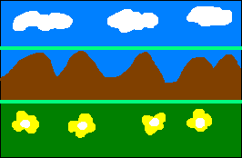
Here I made cuts right above and below the mountain. Everything from the top to the first line is moving slowly, everything to the second line is moving at an average speed, and everything below this line is moving fast. This is a simple but clever trick. And having learned about it, you can notice it in many retro games, mainly for Genesis / Mega Drive, but also on other consoles too. One of the most obvious examples is the part of the cave from Mickey Mania. You can see that the stalagmites and stalactites in the background are divided exactly along the horizontal line with an obvious black border between the layers.
I implemented the same thing in my background. However, there is one trick. Suppose that the foreground moves at one-to-one speed coinciding with the camera movement, and the background speed is one third of the pixel movement of the camera, that is, the background moves as one third of the foreground. But, of course, a third pixel does not exist. So I need to move the background by one pixel for every three pixels of motion.
If they worked with computers capable of mathematical calculations, they would take the camera position, divide it by 3, and make this value a background offset. Unfortunately, the Game Boy is not able to perform division, not to mention the fact that software division is a very slow and painful process. Adding a device for dividing (or multiplying) into a weak CPU for a portable entertainment console in the 80s did not seem to be a cost-effective step, so we will have to invent another way.
In the code, I did the following: instead of reading the position of the camera from a variable, I demanded that it increase or decrease. Thanks to this, with every third increment I can perform the increment of the background position, and with every first increment - the increment of the foreground position. This complicates scrolling to a position from the other edge of the field a bit (the easiest way is to simply reset the position of the layers after a certain transition), but it saves us from having to divide.
Result
After all this, I got the following:
To play the Game Boy, this is actually pretty cool. As far as I know, not all of them have parallax scrolling implemented as follows.