Low-budget stereo rendering in few lines of code (stereogram, anaglyph, stereoscope)
- Tutorial
Another weekend has come, which means I am am writing another couple dozen lines of code and make an illustration or two. In previous articles I’ve explained how to do ray tracing and even blow stuff up. This might surprise you, but computer graphics is quite easy: even a couple hundred lines of bare C++ can produce some very exciting imagery.
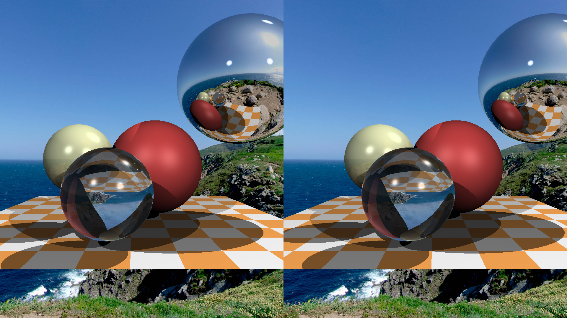
Today’s topic is binocular vision, and we won’t even break the 100 lines barrier doing it. Since we can draw 3D scenes, it’d be foolish to ignore stereo pairs, so today we’ll make something like this:
The sheer insanity of Magic Carpet's creators still blows my mind. For those unaware, this game allowed you to do a 3D render in both anaglyph and stereogram mode from the main settings menu! That was wild for me.
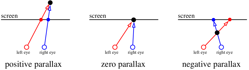
So, let begin. To start, what causes our vision apparatus to perceive depth in objects? There’s a clever term “parallax”. Let’s focus on the screen. Everything that’s within the plane of the screen is registered by our brain as being one object. But if a fly flies between our eyes and the screen, then the brain perceives it as two objects. The spider behind the screen will also be doubled.
Our brain is very efficient at analyzing slightly different images. It uses binocular disparity to get information about depth from 2D images coming from the retina using stereopsis. Well, screw the big words and let us just draw images!
Let’s imagine that our monitor is a window to the virtual world :)
Our task is to draw two images of what we see through that “window”, one for each eye. On the picture above it the red-blue “sandwich”. Let’s forget for now how to deliver these images to our brain, at this stage we just need to save two separate files. In particular, I want to know how to get these images using my tiny raytracer.
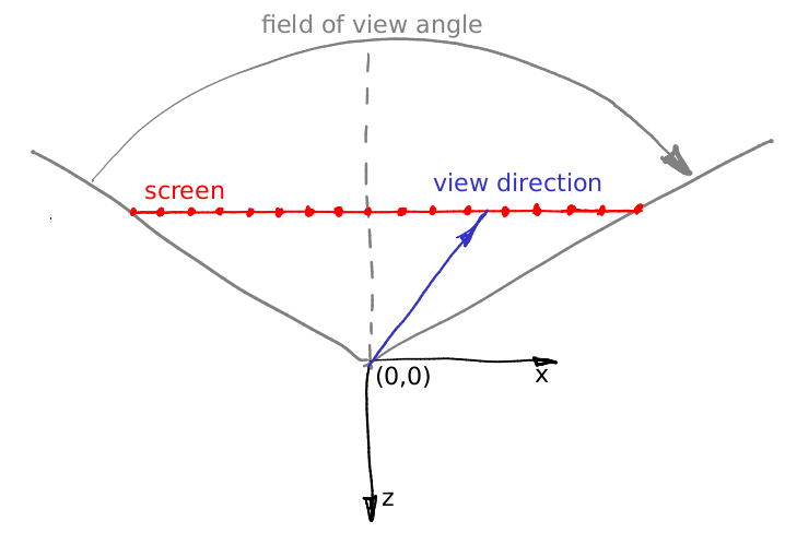
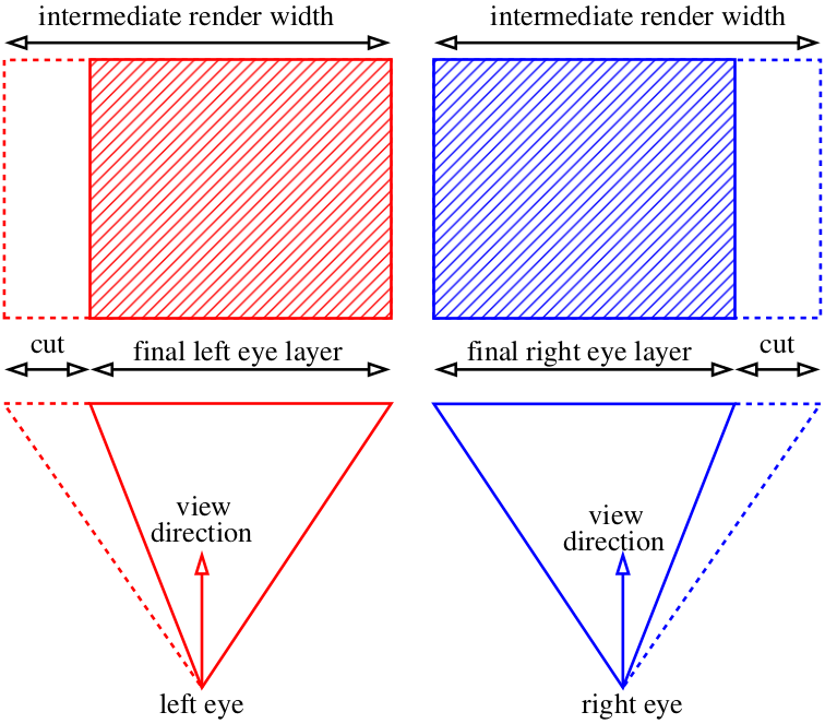
Let’s assume the angle doesn’t change and it’s the (0,0,-1) vector. Let’s assume we can move the camera to the area between the eyes, but then what? One little detail: the view frustum through our “window” is asymmetric. But our ray tracer can only render a symmetric frustum:
And what do we now? Cheat :)
We can render slightly wider images than we need and then just cut out the extra parts:
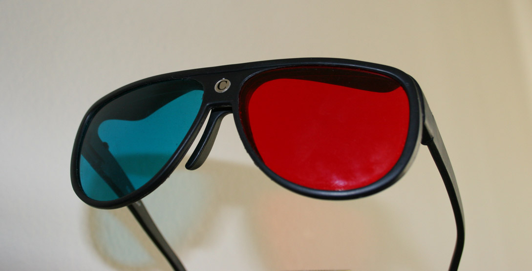
I think we’ve covered the basic rendering mechanism, and now we tackle the issue of delivering the image to our brain. The simplest way is this kind of glasses:
We make two grayscale renders and assign left and right images to to red and blue channels respectively. This is what we get:
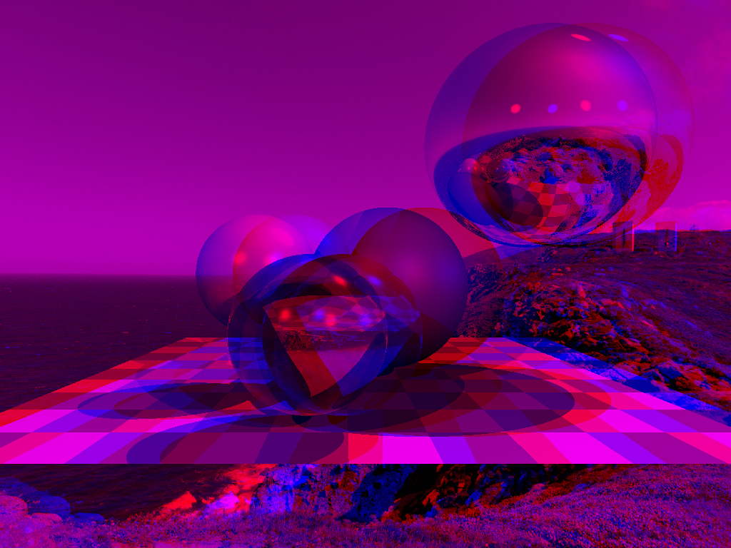
The red glass cuts out one channel, while the blue glass cuts out the other. Combined, the eyes get a different picture and we perceive it in 3D. Here are the modifications to the main commit from the tinyraytracer. The changes include camera positioning for both eyes and channels assembly.
Anaglyph renders is one the oldest way of watching (computer-generated) stereo images. It has a lot of downsides, for example, bad color transmission. But on the other hand, these are very easy to create at home.
If you don't have a compiler on your computer, it's not a problem. If you have a guithub account, you can view, edit and run the code (sic!) in one click in your browser.

When you open this link, gitpod creates a virtual machine for you, launches VS Code, and opens a terminal on the remote machine. In the command history (click on the console and press the up key) there is a complete set of commands that allows you to compile the code, launch it and open the resulting image.
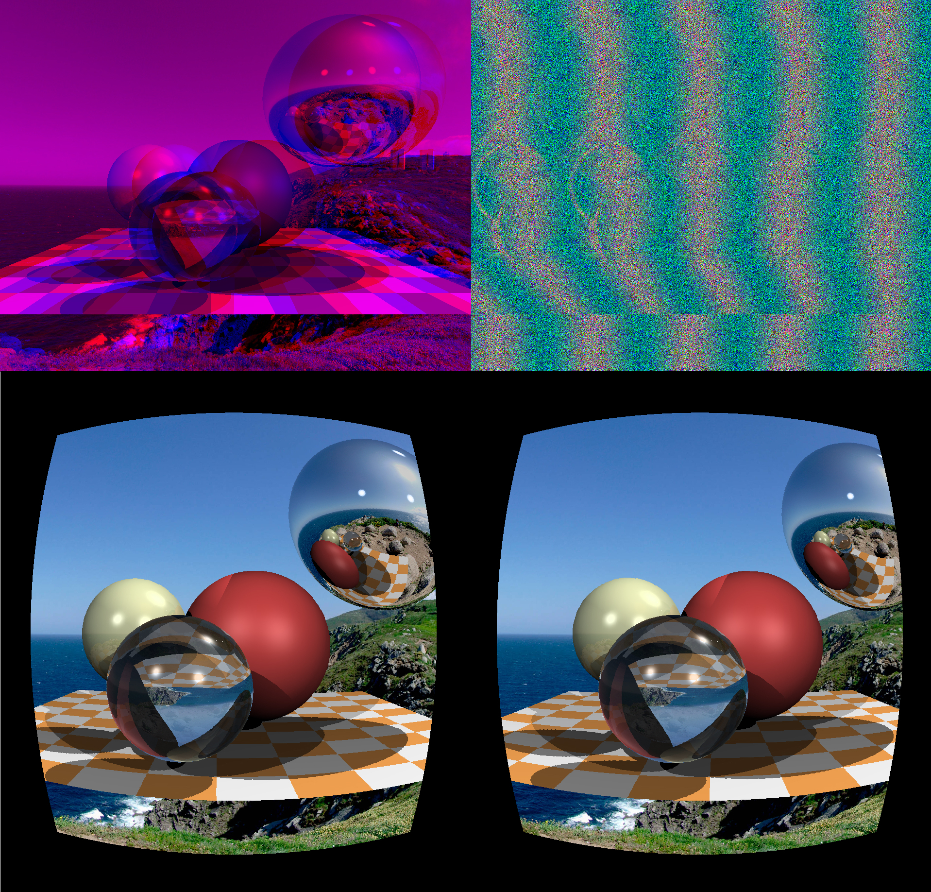
With smartphones becoming mainstream we remembered about the 19th-century invention called the stereoscope. A couple of years ago Google suggested to use two lenses (that, unfortunately, is difficult to create at home, you need to buy it), a bit of cardboard (available anywhere) and a smartphone (in your pocket) to create rather believable VR glasses.
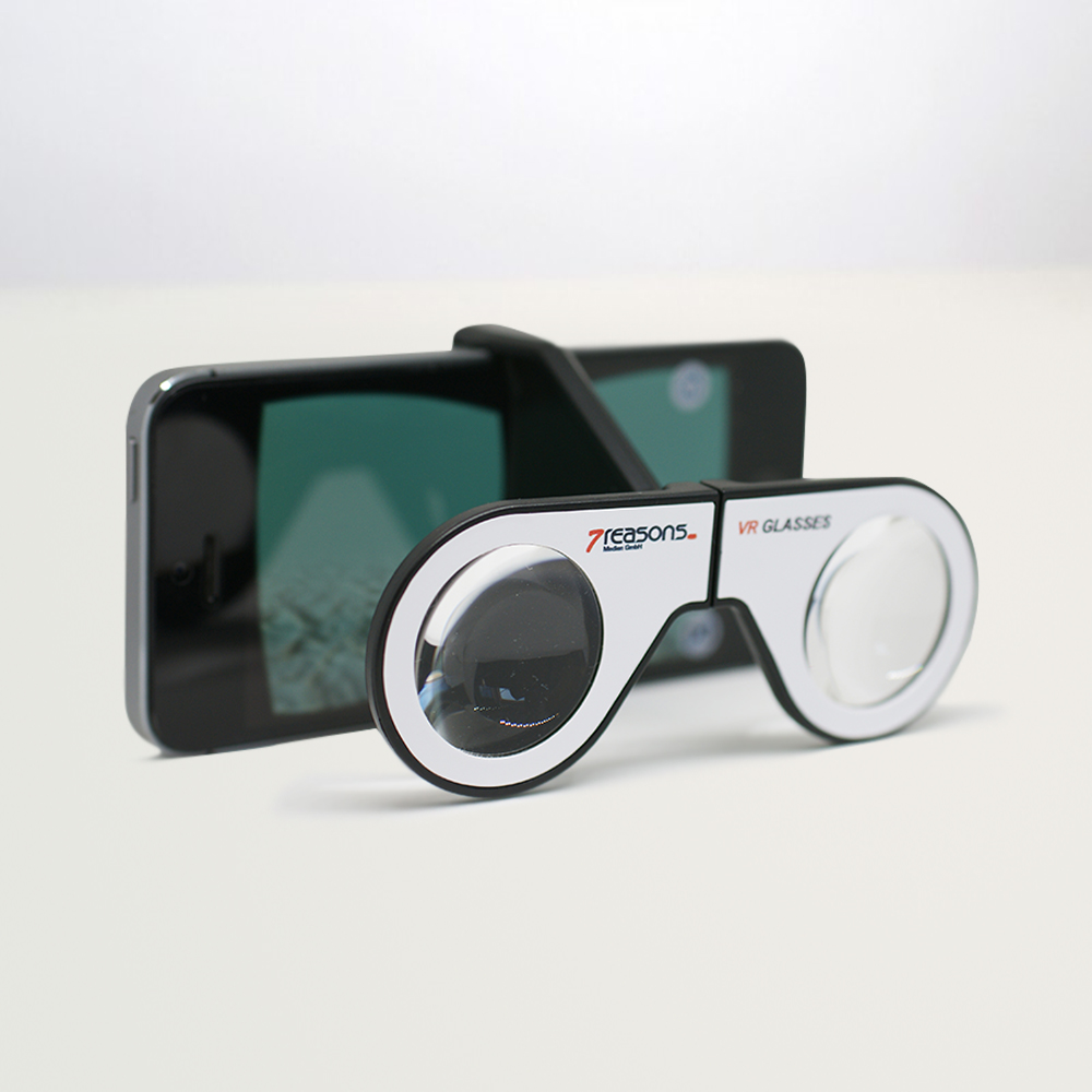
They’re plenty on AliExpress and cost like $3 a pair. Compared to anaglyph rendering we don’t even have too much to do: just take two pictures and put them side by side. Here’s the commit.
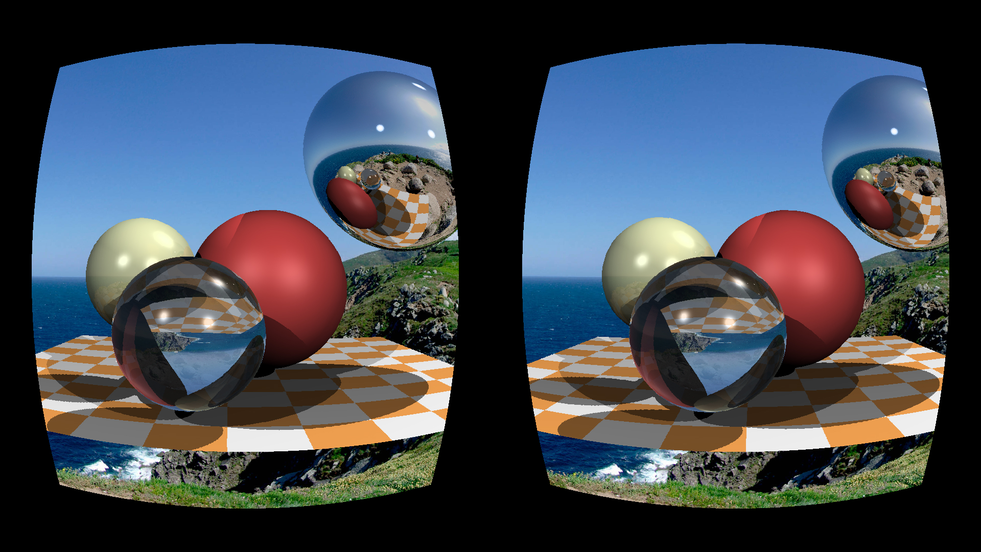
Strictly speaking, depending on the lens we might need to correct for the lens’s distortion, but I didn’t bother with that, since it looked fine regardless. But if we really need to apply the barrel pre-distortion that compensates the natural distortion from the lens, that’s how it looks for my smartphone and my glasses:
Here is the gitpod link:
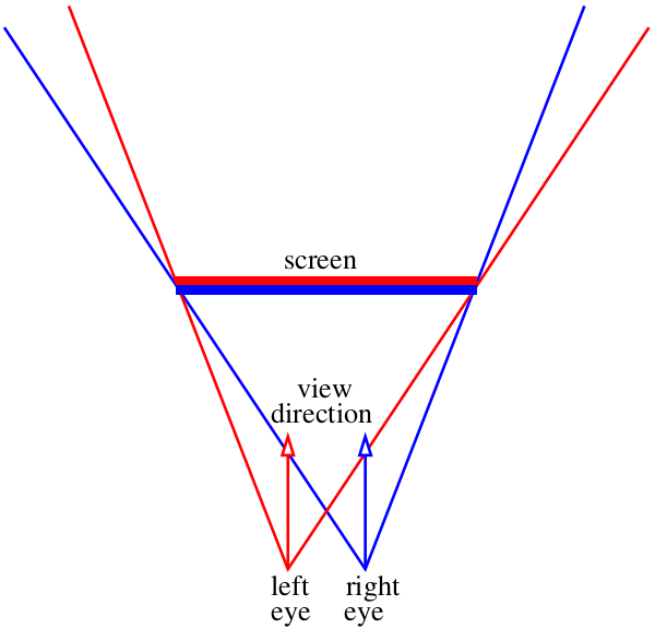
And what do we do if we don’t want to use any extra equipment? Then there’s only one option — squinting. The previous picture, honestly, is quite enough for stereo viewing, just squint your eyes (either crossing the eyes or walling them). Here’s a scheme that tells us how to watch the previous illustration. Two red lines show the images as percieved by the left retina, two blue ones — the right retina.
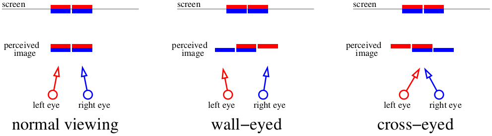
If we focus on the screen, then four images combine into two. If we cross eyes, or focus on a far object, it’s possible to feed the brain “three” images. The central images overlap, which creates the stereo effect.
Different people use different methods: for example, I can’t cross my eyes, but wall them easily. It’s important that the autostereogram built for a certain method should only be viewed with that method, or else we get an inverted depth map (remember positive and negative parallax?). The problem is that it’s hard to cross the eyes much, so it only works on small images. But what if we want bigger ones? Let’s sacrifice the colors entirely and only focus on the depth perception part. Here’s the picture we’re hoping to get by the end of the article:
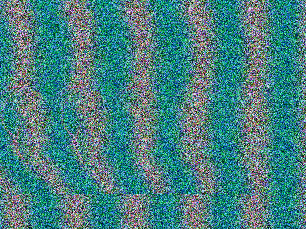
This is a wall-eyed autostereogram. For those who prefer the other method, here’s an image for that. If you’re not used to autostereograms, try different conditions: full screen, smaller image, brightness, darkness. Our goal is to wall our eyes so that the two nearby vertical strips overlap. The easiest thing is to focus on the top-left part of the picture, since it’s plain. Personally, I open the picture in full screen. Don’t forget to remove the mouse cursor too!
Don’t stop at an incomplete 3D effect. If you vaguely see roundish shapes, and the 3D effect is weak, the illusion’s incomplete. The spheres are supposed to “jump” out of the screen towards the viewer, the effect has to be stable and sustainable. The stereopsis has a gisteresis: once you get a stable image, it gets more detailed the longer you observe it. The farther the eyes are from the screen, the bigger the depth perception effect is.
This stereogram was drawn using a method suggested 25 years ago in this article: «Displaying 3D Images: Algorithms for Single Image Random Dot Stereograms».
The starting point for rendering autostereograms is the depth map (since we abandon the colors). This commit draws the following image:
The closer and further planes set our depth: the farthest point in my map has the depth of 0, while the closest one has the depth of 1.
Let’s say our eyes are at d distance from the screen. We put our (imaginary) far plane (z=0) at the same distance “behind” the screen. We choose the μ variable, which determines the location of the near plane (z=1), that will be at μd distance from the far plane. For my code I chose μ=⅓. Overall, our entire “world” lives at distance from d-μd to d behind the screen. Let’s say we know the distance between the eyes (in pixels, I chose 400 pixels):
If we look at the red dot, then two pixels marked in green should have the same color in the stereogram. How to calculate the distance between them? Easy. If the current projected dot has the depth of z, then the parallax divided by the distance between eyes equals the fraction between corresponding depths: p/e = (d-dμz)/(2d-dμz). By the way, notice that d is simplified out and does not appear anywhere else! Then p/e = (1-μz)/(2-μz), meaning the parallax equals p=e*(1-μz)/(2-μz) pixels.
The main idea behind autostereogram is: we go through the entire depth map, for each depth value we determine which pixels will have the same color and put it down into our system of constraints. Then we start from the random image and try to satisfy all the constraints we have set previously.
Here we prepare the image that will later be constrained by parallax constraints. Here’s the commit, and it draws this:

Note that the colors are mostly random, apart from the red channel where I put rand()*sin to create a periodic pattern. The stripes are 200 pixels apart, which is (given μ=1/3 и e=400) the maximum parallax value in our world (the far plane). The pattern is not technically necessary, but it'll help to focus the eyes.
Actually, the the full code that draws the autostereogram looks like this:
Here’s the commit, the int parallax(const float z) function gives us distance between pixels of the same color for the current depth value. We render the stereogram line by line, since lines are independent from each other (we don’t have vertical parallax). The main loop simply iterates through each line; each time it starts with an unlimited set of pixels, and then for each pixel it adds one equality constraint. At the end, it gives us a certain number of clusters of same colored pixels. For example, pixels with indexes left and right should end up identical.
How to store this set of constraints? The simplest way is the union-find data structure. I won’t go into detail, just go to Wikipedia, it’s literally three lines of code. The main point is that for each cluster there’s a certain “root” pixel responsible for the cluster. The root pixel keeps its initial color, and all other pixels in the cluster are to be updated:
That’s it, really. Twenty lines of code and our autostereogram is ready for you to break your eyes over it. By the way, if we try hard enough, it is possible to transmit color information.
I did not cover other stereoscopic systems like polarized 3D systems, since they’re much more expensive to make. If I missed something, feel free to correct me!
Today’s topic is binocular vision, and we won’t even break the 100 lines barrier doing it. Since we can draw 3D scenes, it’d be foolish to ignore stereo pairs, so today we’ll make something like this:
The sheer insanity of Magic Carpet's creators still blows my mind. For those unaware, this game allowed you to do a 3D render in both anaglyph and stereogram mode from the main settings menu! That was wild for me.
Parallax
So, let begin. To start, what causes our vision apparatus to perceive depth in objects? There’s a clever term “parallax”. Let’s focus on the screen. Everything that’s within the plane of the screen is registered by our brain as being one object. But if a fly flies between our eyes and the screen, then the brain perceives it as two objects. The spider behind the screen will also be doubled.
Our brain is very efficient at analyzing slightly different images. It uses binocular disparity to get information about depth from 2D images coming from the retina using stereopsis. Well, screw the big words and let us just draw images!
Let’s imagine that our monitor is a window to the virtual world :)
Our task is to draw two images of what we see through that “window”, one for each eye. On the picture above it the red-blue “sandwich”. Let’s forget for now how to deliver these images to our brain, at this stage we just need to save two separate files. In particular, I want to know how to get these images using my tiny raytracer.
Let’s assume the angle doesn’t change and it’s the (0,0,-1) vector. Let’s assume we can move the camera to the area between the eyes, but then what? One little detail: the view frustum through our “window” is asymmetric. But our ray tracer can only render a symmetric frustum:
And what do we now? Cheat :)
We can render slightly wider images than we need and then just cut out the extra parts:
Anaglyph
I think we’ve covered the basic rendering mechanism, and now we tackle the issue of delivering the image to our brain. The simplest way is this kind of glasses:
We make two grayscale renders and assign left and right images to to red and blue channels respectively. This is what we get:
The red glass cuts out one channel, while the blue glass cuts out the other. Combined, the eyes get a different picture and we perceive it in 3D. Here are the modifications to the main commit from the tinyraytracer. The changes include camera positioning for both eyes and channels assembly.
Anaglyph renders is one the oldest way of watching (computer-generated) stereo images. It has a lot of downsides, for example, bad color transmission. But on the other hand, these are very easy to create at home.
If you don't have a compiler on your computer, it's not a problem. If you have a guithub account, you can view, edit and run the code (sic!) in one click in your browser.
When you open this link, gitpod creates a virtual machine for you, launches VS Code, and opens a terminal on the remote machine. In the command history (click on the console and press the up key) there is a complete set of commands that allows you to compile the code, launch it and open the resulting image.
Stereoscope
With smartphones becoming mainstream we remembered about the 19th-century invention called the stereoscope. A couple of years ago Google suggested to use two lenses (that, unfortunately, is difficult to create at home, you need to buy it), a bit of cardboard (available anywhere) and a smartphone (in your pocket) to create rather believable VR glasses.
They’re plenty on AliExpress and cost like $3 a pair. Compared to anaglyph rendering we don’t even have too much to do: just take two pictures and put them side by side. Here’s the commit.
Strictly speaking, depending on the lens we might need to correct for the lens’s distortion, but I didn’t bother with that, since it looked fine regardless. But if we really need to apply the barrel pre-distortion that compensates the natural distortion from the lens, that’s how it looks for my smartphone and my glasses:
Here is the gitpod link:
Autostereograms
And what do we do if we don’t want to use any extra equipment? Then there’s only one option — squinting. The previous picture, honestly, is quite enough for stereo viewing, just squint your eyes (either crossing the eyes or walling them). Here’s a scheme that tells us how to watch the previous illustration. Two red lines show the images as percieved by the left retina, two blue ones — the right retina.
If we focus on the screen, then four images combine into two. If we cross eyes, or focus on a far object, it’s possible to feed the brain “three” images. The central images overlap, which creates the stereo effect.
Different people use different methods: for example, I can’t cross my eyes, but wall them easily. It’s important that the autostereogram built for a certain method should only be viewed with that method, or else we get an inverted depth map (remember positive and negative parallax?). The problem is that it’s hard to cross the eyes much, so it only works on small images. But what if we want bigger ones? Let’s sacrifice the colors entirely and only focus on the depth perception part. Here’s the picture we’re hoping to get by the end of the article:
This is a wall-eyed autostereogram. For those who prefer the other method, here’s an image for that. If you’re not used to autostereograms, try different conditions: full screen, smaller image, brightness, darkness. Our goal is to wall our eyes so that the two nearby vertical strips overlap. The easiest thing is to focus on the top-left part of the picture, since it’s plain. Personally, I open the picture in full screen. Don’t forget to remove the mouse cursor too!
Don’t stop at an incomplete 3D effect. If you vaguely see roundish shapes, and the 3D effect is weak, the illusion’s incomplete. The spheres are supposed to “jump” out of the screen towards the viewer, the effect has to be stable and sustainable. The stereopsis has a gisteresis: once you get a stable image, it gets more detailed the longer you observe it. The farther the eyes are from the screen, the bigger the depth perception effect is.
This stereogram was drawn using a method suggested 25 years ago in this article: «Displaying 3D Images: Algorithms for Single Image Random Dot Stereograms».
Let us start
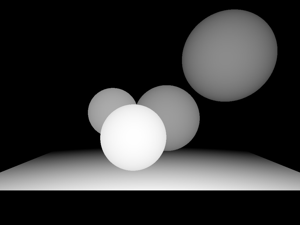
The starting point for rendering autostereograms is the depth map (since we abandon the colors). This commit draws the following image:
The closer and further planes set our depth: the farthest point in my map has the depth of 0, while the closest one has the depth of 1.
The core principles
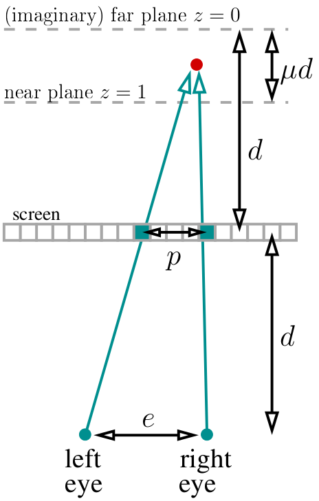
Let’s say our eyes are at d distance from the screen. We put our (imaginary) far plane (z=0) at the same distance “behind” the screen. We choose the μ variable, which determines the location of the near plane (z=1), that will be at μd distance from the far plane. For my code I chose μ=⅓. Overall, our entire “world” lives at distance from d-μd to d behind the screen. Let’s say we know the distance between the eyes (in pixels, I chose 400 pixels):
If we look at the red dot, then two pixels marked in green should have the same color in the stereogram. How to calculate the distance between them? Easy. If the current projected dot has the depth of z, then the parallax divided by the distance between eyes equals the fraction between corresponding depths: p/e = (d-dμz)/(2d-dμz). By the way, notice that d is simplified out and does not appear anywhere else! Then p/e = (1-μz)/(2-μz), meaning the parallax equals p=e*(1-μz)/(2-μz) pixels.
The main idea behind autostereogram is: we go through the entire depth map, for each depth value we determine which pixels will have the same color and put it down into our system of constraints. Then we start from the random image and try to satisfy all the constraints we have set previously.
Preparing the source image
Here we prepare the image that will later be constrained by parallax constraints. Here’s the commit, and it draws this:
Note that the colors are mostly random, apart from the red channel where I put rand()*sin to create a periodic pattern. The stripes are 200 pixels apart, which is (given μ=1/3 и e=400) the maximum parallax value in our world (the far plane). The pattern is not technically necessary, but it'll help to focus the eyes.
Autostereogram rendering
Actually, the the full code that draws the autostereogram looks like this:
intparallax(constfloat z){
    constfloat eye_separation = 400.; // interpupillary distance in pixelsconstfloat mu = .33;              // if the far plane is a distance D behind the screen, then the near plane is a distance mu*D in front of the far planereturnstatic_cast<int>(eye_separation*((1.-z*mu)/(2.-z*mu))+.5);
}
size_t uf_find(std::vector<size_t> &same, size_t x) {
    return same[x]==x ? x : uf_find(same, same[x]);
}
voiduf_union(std::vector<size_t> &same, size_t x, size_t y){
    if ((x=uf_find(same, x)) != (y=uf_find(same, y))) same[x] = y;
}
intmain(){
[...]
    for (size_t j=0; j<height; j++) { // autostereogram rendering loopstd::vector<size_t> same(width);
        std::iota(same.begin(), same.end(), 0); // initialize the union-find data structure (same[i]=i)for (size_t i=0; i<width; i++) { // put the constraintsint par = parallax(zbuffer[i+j*width]);
            int left  = i - par/2;
            int right = left + par; // works better than i+par/2 for odd values of parif (left>=0 && right<(int)width)
                uf_union(same, left, right); // left and right pixels will have the same color
        }
        for (size_t i=0; i<width; i++) { // resolve the constraintssize_t root = uf_find(same, i);
            for (size_t c=0; c<3; c++)
                framebuffer[(i+j*width)*3+c] = framebuffer[(root+j*width)*3+c];
        }
    }
[...]
Here’s the commit, the int parallax(const float z) function gives us distance between pixels of the same color for the current depth value. We render the stereogram line by line, since lines are independent from each other (we don’t have vertical parallax). The main loop simply iterates through each line; each time it starts with an unlimited set of pixels, and then for each pixel it adds one equality constraint. At the end, it gives us a certain number of clusters of same colored pixels. For example, pixels with indexes left and right should end up identical.
How to store this set of constraints? The simplest way is the union-find data structure. I won’t go into detail, just go to Wikipedia, it’s literally three lines of code. The main point is that for each cluster there’s a certain “root” pixel responsible for the cluster. The root pixel keeps its initial color, and all other pixels in the cluster are to be updated:
for (size_t i=0; i<width; i++) { // resolve the constraintssize_t root = uf_find(same, i);
            for (size_t c=0; c<3; c++)
                framebuffer[(i+j*width)*3+c] = framebuffer[(root+j*width)*3+c];
        }
Conclusion
That’s it, really. Twenty lines of code and our autostereogram is ready for you to break your eyes over it. By the way, if we try hard enough, it is possible to transmit color information.
I did not cover other stereoscopic systems like polarized 3D systems, since they’re much more expensive to make. If I missed something, feel free to correct me!