We create effect of distribution of color in Unity
- Transfer
This effect was inspired by the episode of Powerpuff Girls . I wanted to create the effect of color propagation in a black and white world, but to realize it in the coordinates of world space , to see how color paints objects , and not just flatly distributed across the screen, as in a cartoon.
I created the effect in the new Lightweight Rendering Pipeline Unity engine, the built-in example of the Scriptable Rendering Pipeline. All concepts apply to other pipelines, but some built-in functions or matrices may have different names. I also used the new post-processing stack, but in the tutorial I’ll omit the detailed description of its settings, because it is fairly well described in other manuals, for example, inthis video .
The effect of post-processing in grayscale
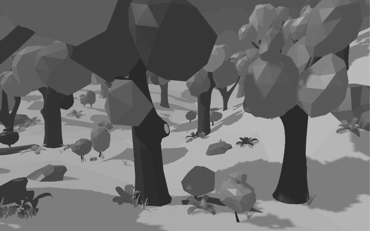
Just for reference, this is what the scene looks like without post-processing effects.

For this effect, I used the new package, Unity 2018 Post-Processing, which can be downloaded from the package manager. If you do not know how to use it, then I recommend this tutorial .
I wrote my own effect by extending the PostProcessingEffectSettings and PostProcessEffectRenderer classes written in C #, the source code of which can be seen here . In fact, I didn’t do anything particularly interesting with these effects on the CPU side (in C # code), except that I added a group of general properties to the Inspector, so I won’t explain in the tutorial how this is done. I hope my code speaks for itself.
Let's move on to the shader code and start off with a grayscale effect. In the tutorial, we will not change the shaderlab file, the input structures and the vertex shader, so you can see their source code here . Instead, we will do a fragment shader.
To convert color to grayscale, we reduce the value of each pixel to the luminance value , which describes its brightness . This can be done by taking the dot product of the color value of the camera texture and the weighted vector , which describes the contribution of each color channel to the overall brightness of the color.
Why do we use scalar product? Do not forget that scalar products are calculated as follows:
dot(a, b) = ax * bx + ay * by + az * bzIn this case, we multiply each color value channel by weight . Then we add these pieces to reduce them to a single scalar value. When the RGB color has the same values in the R, G, and B channels, the color becomes gray.
This is what the shader code looks like:
float4 fullColor = SAMPLE_TEXTURE2D(_MainTex, sampler_MainTex, i.screenPos);
float3 weight = float3(0.299, 0.587, 0.114);
float luminance = dot(fullColor.rgb, weight);
float3 greyscale = luminance.xxx;
return float4(greyscale, 1.0);
If the base shader is configured correctly, then the post-processing effect should color the entire screen in grayscale.
Drawing the effect of color in global space
Since this is a post-processing effect, in the vertex shader we have no information about the geometry of the scene. At the post-processing stage, the only information we have is the image rendered by the camera and the space of the truncated coordinates for its sampling. However, we want the coloring effect to spread across objects as if it were happening in the world, and not just on a flat screen.
To draw this effect in the scene geometry, we need the coordinates of the world space of each pixel. To go from the coordinates of the space of truncated coordinates to the coordinates of world space , we need to performcoordinate space transform .
Usually, in order to go from one space of coordinates to another, a matrix is needed that specifies a transformation from the space of coordinates A to space B. To go from A to B, we multiply a vector in the coordinate space A by this transformation matrix. In our case, we will perform the following transition: space of truncated coordinates (clip space) -> view space (view space) -> world space (world space) . That is, we need the clip-to-view-space matrix and the view-to-world-space matrix that Unity provides.
However, the coordinates of the truncated coordinates space provided by Unity are missing zthat defines the pixel depth, or distance to the camera. We need this value to go from the space of truncated coordinates to the species space. Let's start with that!
Getting the value of the depth buffer
If the rendering pipeline is turned on, then it draws in the viewport a texture that stores the z values in a structure called the depth buffer . We can sample this buffer to get the missing z value of our coordinate space of truncated coordinates!
First, make sure that the depth buffer is actually rendered by clicking on the “Add Additional Data” section of the camera in the Inspector and checking that the “Depth Texture” checkbox is checked. Also ensure that the “Allow MSAA” option is enabled for the camera. I do not know why for the effect to work, you need to check this box, but it is so. If the depth buffer is drawn, thenyou should see the Depth Prepass stage in the frame debugger .
Create a _CameraDepthTexture sampler in the hlsl file
TEXTURE2D_SAMPLER2D(_CameraDepthTexture, sampler_CameraDepthTexture);Now let's write the GetWorldFromViewPosition function and for the time being we will use it to check the depth buffer . (We will expand it later to get a position in the world.)
float3 GetWorldFromViewPosition(VertexOutput i){
  float z = SAMPLE_DEPTH_TEXTURE(_CameraDepthTexture, sampler_CameraDepthTexture, i.screenPos).r;
  return z.xxx;
}
In the fragment shader, we will draw the value of the sample texture of the depths.
float3 depth = GetWorldFromViewPosition(i);
return float4(depth, 1.0);
Here is what my results look like when there is only one hilly plain in the scene (I turned off all the trees in order to further simplify the testing of the values of world space). Your result should look like. Black and white values describe the distances from the geometry to the camera.

Here are some steps you can take if you have problems:
- Make sure that the camera has a depth texture rendering enabled.
- Make sure the camera has MSAA turned on.
- Try changing the near and far plane of the camera.
- Make sure that the objects you expect to see in the depth buffer use a shader with a depth pass (depth pass). This ensures that the object is rendering to the depth buffer. All standard shaders in LWRP do this.
Getting value in global space
Now that we have all the necessary information for the space of truncated coordinates , let's transform into a species space , and then into world space .
Note that the transformation matrices required for these operations are already in the SRP library. However, they are contained in the Unity C # library, so I inserted them into the shader in the Render function of the ColorSpreadRenderer script :
sheet.properties.SetMatrix("unity_ViewToWorldMatrix", context.camera.cameraToWorldMatrix);
sheet.properties.SetMatrix("unity_InverseProjectionMatrix", projectionMatrix.inverse);
Now let's extend our GetWorldFromViewPosition function.
First, we need to obtain a position in the view space by performing a multiplication of the position in the space of truncated coordinates by InverseProjectionMatrix . We will also need to perform some more voodoo magic with a screen position that is related to the way Unity stores the position in the space of truncated coordinates.
Finally, we can multiply the position in the view space by ViewToWorldMatrix to get a position in the world space .
float3 GetWorldFromViewPosition(VertexOutput i){
  // получаем значение глубиныfloat z = SAMPLE_DEPTH_TEXTURE(_CameraDepthTexture, sampler_CameraDepthTexture, i.screenPos).r;
  // получаем позицию в видовом пространстве
  float4 result = mul(unity_InverseProjectionMatrix, float4(2*i.screenPos-1.0, z, 1.0));
  float3 viewPos = result.xyz / result.w;
  // получаем позицию в мировом пространстве
  float3 worldPos = mul(unity_ViewToWorldMatrix, float4(viewPos, 1.0));
  return worldPos;
}
Let's run a check to make sure that the positions in world space are correct. To do this, I wrote a shader that returns only the position of the object in world space ; This is a fairly simple calculation based on the usual shader, the correctness of which can be trusted. Disable the post-processing effect and take a screenshot of this test shader of global space . My after applying the shader to the surface of the earth in the scene looks like this:
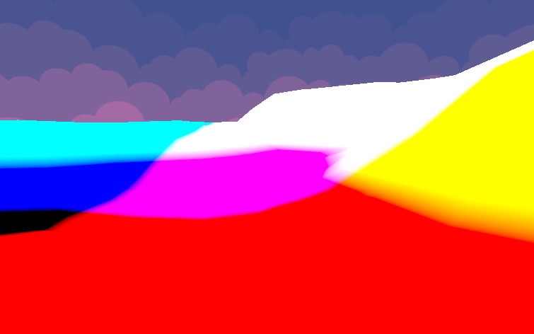
(Note that the values in world space are much larger than 1.0, so do not worry about these colors having any meaning; instead, just make sure that the results are the same for the "correct" and "calculated" answers.) Next, let's return to the test The object is a regular material (and not a world space test material), and then re-enable the post-processing effect. My results look like this:

This is completely similar to the test shader written by me, that is, the calculations of the world space are most likely correct!
Drawing a circle in the world space
Now that we have positions in global space , we can draw a circle of colors in the scene! We need to set the radius within which the effect will draw the color. Beyond it, the effect will draw a picture in grayscale. To set it, you need to adjust the values for the radius of the effect ( _MaxSize ) and the center of the circle (_Center). I set these values in the C # ColorSpread class so that they are visible in the inspector. Let's extend our fragment shader by making it check whether the current pixel is inside the radius of the circle :
float4 Frag(VertexOutput i) : SV_Target
{
  float3 worldPos = GetWorldFromViewPosition(i);
  // проверяем, находится ли расстояние в пределах макс. радиуса// выбираем градации серого, если за пределами, полный цвет, если внутриfloat dist = distance(_Center, worldPos);
  float blend = dist <= _MaxSize? 0 : 1;
  // обычный цвет
  float4 fullColor = SAMPLE_TEXTURE2D(_MainTex, sampler_MainTex, i.screenPos);
  // градации серогоfloat luminance = dot(fullColor.rgb, float3(0.2126729, 0.7151522, 0.0721750));
  float3 greyscale = luminance.xxx;
  // решает, выбрать ли цвет или градации серого
  float3 color = (1-blend)*fullColor + blend*greyscale;
  return float4(color, 1.0);
}
Finally, we will be able to draw the color based on whether it is within a radius in world space . This is what the base effect looks like!

Adding special effects
I will consider a couple of techniques used to color spread across the ground. There is much more in the full effect, but the tutorial has already become too large, so we limit ourselves to the most important.
Circle zoom animation
We want the effect to spread around the world, that is, as it were grow. To do this, you need to change the radius depending on the time.
_StartTime indicates the time at which the circle should start to grow. In my project, I used an additional script that allows you to click anywhere on the screen to start the growth of the circle; in this case, the start time is equal to the mouse click time.
_GrowthSpeed sets the speed of increasing the circle.
// вычисляем радиус на основании времени начала анимации и текущего времениfloat timeElapsed = _Time.y - _StartTime;
float effectRadius = min(timeElapsed * _GrowthSpeed, _MaxSize);
// ограничиваем радиус, чтобы не получить странных артефактов
effectRadius = clamp(effectRadius, 0, _MaxSize);
We also need to update the distance check to compare the current distance with the increasing radius of the effect , not _MaxSize.
// проверяем, находится ли расстояние в пределах текущего радиуса эффекта// выбираем градации серого, если за пределами, полный цвет, если внутриfloat dist = distance(_Center, worldPos);
float blend = dist <= effectRadius? 0 : 1;
// вся остальная работа с цветом...
Here's what the result should look like:
Adding Noise to Radius
I wanted the effect to be more like a blur of paint, and not just a growing circle. To do this, let's add noise to the radius of the effect so that the propagation is uneven.
First we need to sample the texture in the global space . The UV coordinates of i.screenPos are in screen space , and if we perform sampling based on them, the shape of the effect will move with the camera; so let's use the coordinates in world space . I added the _NoiseTexScale parameter to control the scale of the noise texture sample , because the coordinates in world space are quite large.
// получаем для текстуры шума позицию сэмплирования в мировом пространстве
float2 worldUV = worldPos.xz;
worldUV *= _NoiseTexScale;
Now let's sample the noise texture and add this value to the radius of the effect. I used the _NoiseSize scale for more control over the size of the noise.
// прибавляем шум к радиусуfloat noise = SAMPLE_TEXTURE2D(_NoiseTex, sampler_NoiseTex, worldUV).r;
effectRadius -= noise * _NoiseSize;
Here are the results after some tweaking:
In conclusion
You can follow tutorials for updates on my Twitter account , and on Twitch I spend streaming over coding! (I also stream games from time to time, so don’t be surprised if you see me in my pajamas and play Kingdom Hearts 3.)
Thanks:
- All project models are taken in this LowPoly Environment Pack from the Unity store.
- The effect of ScreenSpaceReflections from the Unity engine helped me a lot to figure out how to get a three-dimensional position in the view space from the two-dimensional UV-coordinates of the screen space.