Restore another PDP-11/04
- Transfer
Translation of another PDP-11/04 recovery article. You can read the last trilogy here - part 1 (PDP-11/04 itself), part 2 (TU60 tape station), part 3 (terminal LA30). Italics are my comments.
We got this device from Gunnar Barbro, and with it came a bunch of different goodies for the PDP-11. But the state of the computer itself was far from perfect. There were not enough processor and memory cards, the power switch was replaced by a remake, and besides, everything was terribly dusty. The KY11-LB, XY11 programming console board (a module for controlling a plotter, for example, IBM 1627, which came with DEC machines and was canonical CalComp 565 ), KW11-P ( programmable RTC module, yes, were connected to the backplane ) Yes, there was a whole board under RTC! ), the main board RK11-D with a set of modules (a controller for magnetic disk drives, it was a set of cards (3 or 4 pieces), combined by a common board ), and DR11-B (DMA controller, which, again, consisted of several boards: M7194, M971, M5916, M7820, ... ), also with all modules.
We disassembled the computer into parts and gently washed them with soap and water, and then blew them dry with a compressor. After drying, they were collected into a single whole. During these procedures, rust spots were found here and there.
Of course, nothing worked even when we connected the processor and memory boards taken from our stocks! The console was dead. If at first we could dial digital codes, and they were displayed on the console ( seven-segment six-digit indicator ), then after some time the situation worsened, and this opportunity disappeared.
KY11-LB is a very interesting option available for PDP-11/04 and PDP-11/34. You can not only turn the CPU on and off, debug the code, view and change the memory, thus entering programs and data into the machine, but also use the service mode, in which step-by-step debugging of the processor microcode is available! This feature is provided by connecting a pair of loops to the processor module. But if the processor is missing or freezes, then the KY11-LB allows you to work with Unibus (a bus connecting modules in many DEC computers) without the participation of the CPU. This is realized due to the presence of its own microprocessor i8008. In the photo below I circled it in red. And this is great news if you need to check the operation of the bus itself or conduct simple tests of memory and I / O cards. When a non-existent destination is requested, the BUS ERR lamp lights up. Jörg Hoppe wrote an excellent document on the use of the KY11-LB.

Having connected the logic analyzer, I checked that the 8008 on the M7859 (KY11-LB) board works normally and executes the recorded program correctly. But the code considered that no one presses any keys ... It turned out that all CLR signals ( clear, a signal to clear the register ) for the output registers were in an active state. The unibus bus controller that processed the DCLO signal (the signal on the Unibus bus, which informs that the DC voltage is too low ) was buggy. Several open collector buffer drivers and register chips were faulty. As soon as I replaced them, the console came to life! But again there was a failure after starting the processor and testing it with diagnostics of its functionality. And twice. The first is a bug in the M9301, the boot board. The 8th bit on the data bus was the last available for the bus driver. He could not read enough data from the bus. The second time, the processor simply freezes. Nothing was set on the address bus, and the examination of the microcode showed that the plug happened while trying to capture the bus. The processor only started up after I took out the M7859 ( KY11-LB) It turned out that the M7859 generated a 9MHz BBSY signal on the Unibus bus ( Bus Busy, in the active state, signals that D0-D15 signals (the requested data were coming through them) are being used by someone ). Why? One trigger 7474 broke and oscillated like crazy. After replacing it, the processor and memory diagnostics were successful!
In PDP-11/04, the M9301-YB is a bootstrap module and terminator. The board’s PROM stores the console emulator and boot code for several common devices. In order for the processor to start execution immediately after starting from the boot area in the PROM, the module generates a special address 0173000 on the bus ( 300ms pulse using the multivibrator 9602 ) ( often an octal number system is used for pdp, therefore zeros at the beginning of numbers are not padding, namely a reference to CC ), and the processor requests the resume address after a power failure, setting the address 024/026 on the Unibus bus ( at the first address the MMIO register in which the PC is located, at the second - PSW, processor status word, various flags and processor status) As a result, a request for data is sent to the bus at addresses 0173024 and 0173026. For cell 0173024, M9301 finds a correspondence between the set of microswitch values ( in the photo, right in the center, 10 pieces ) and the data in PROM. These switches, in fact, determine from which address in the 0173xxx space the processor will begin execution. I dumped four PROM chips - 23-038A9 , 23-039A9 , 23-040A9 and 23-041A9 . Since the M9301-YB inverts some bits to support the possibility of disjunction of the board switches with external signals ( in the photo contacts are TP1 / TP2 / TP3, their OR values are with the values of microswitches on the board, for example, TP1 is connected to S1 and S2 ), I wrote a smalla program that combines these four files into a single binary . Having done only the initial analysis of the disassembler listing, I, however, already noticed that the code is very similar to the PROM from M9301-YA, except that the blocks of code are scattered at different addresses.

To run each of these programs, you need the appropriate procedure in the bootloader code. Typically, such procedures are carried out in a separate PROM chip, the execution of the code from which occurs when typing certain characters in the console emulator. But on this machine there is a M9201-YB board that does not contain a DU primary bootloader ( DEC has very informative names, DU is a bootloader from the media via MSCP (MSCP is a protocol for communicating with drives, such as ATAPI) ). So I had to hammer this bootloader manually (the console emulator, which is part of this module, supports 4 functions - loading the address L, reading memory at address E, writing to address D, starting execution of S, which allows you to enter the code manually. The sequence of commands of the type L 016000, D XXXXXX, D XXXXXX, ..., S 16002 ). It was not easy to find a suitable working bootloader, but I still came across one in the source SimH ( emulator of different ancient systems ). Using PDP11GUI , I uploaded a small file to the machine’s memory. And it works (at least in most cases).
Dump this MSCP bootloader:
Start filling the memory with 016000, and execution with 016002 ( 0x4455 - magic word ).

After that, I tried to start the disk image with XXDP v2.2. But, alas, there was no success. The XXDP command line appeared, but any commands that worked with the disk, such as “D” ( get a list of files on the loaded media ), ended with an error in the “? RD ERR” console. It looks as if the program cannot access the disk. So I checked the small distribution kit RT11 ( real-time operating system for PDP-11 ). Created a disk image with version 5.3 and tried to start. And everything went great! You can play Adventure or program on BASIC'e!
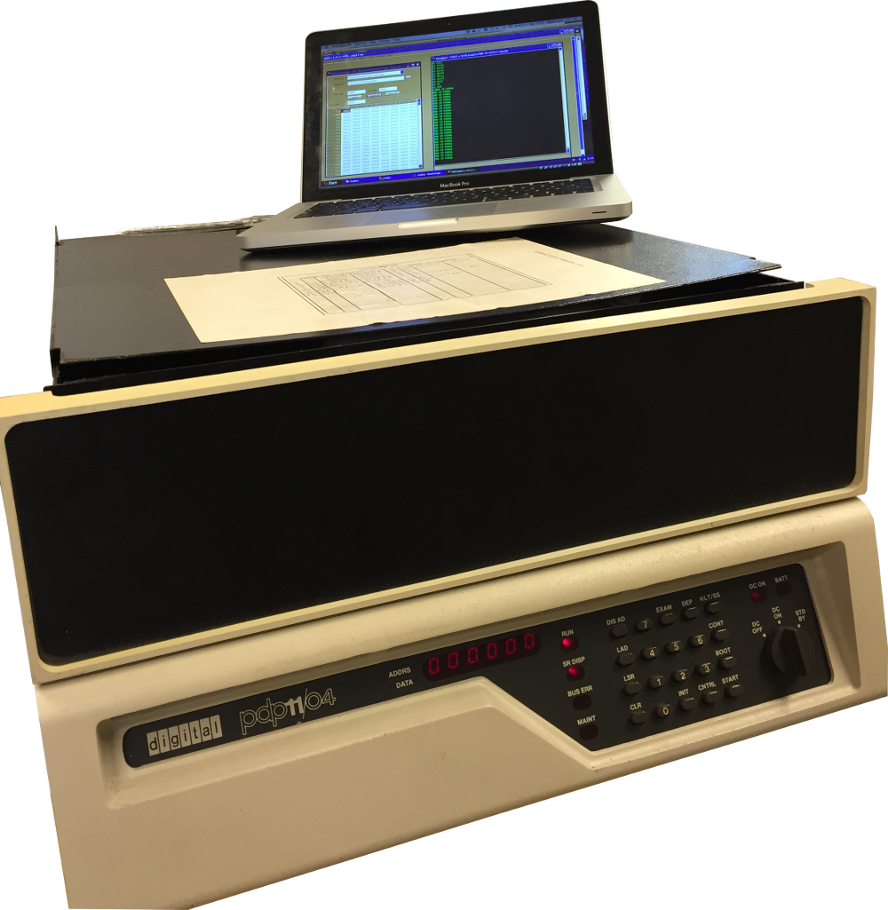
PDP-11/04, sent by Gunnar
We got this device from Gunnar Barbro, and with it came a bunch of different goodies for the PDP-11. But the state of the computer itself was far from perfect. There were not enough processor and memory cards, the power switch was replaced by a remake, and besides, everything was terribly dusty. The KY11-LB, XY11 programming console board (a module for controlling a plotter, for example, IBM 1627, which came with DEC machines and was canonical CalComp 565 ), KW11-P ( programmable RTC module, yes, were connected to the backplane ) Yes, there was a whole board under RTC! ), the main board RK11-D with a set of modules (a controller for magnetic disk drives, it was a set of cards (3 or 4 pieces), combined by a common board ), and DR11-B (DMA controller, which, again, consisted of several boards: M7194, M971, M5916, M7820, ... ), also with all modules.
Cleaning
We disassembled the computer into parts and gently washed them with soap and water, and then blew them dry with a compressor. After drying, they were collected into a single whole. During these procedures, rust spots were found here and there.
Assembly and inspection
Of course, nothing worked even when we connected the processor and memory boards taken from our stocks! The console was dead. If at first we could dial digital codes, and they were displayed on the console ( seven-segment six-digit indicator ), then after some time the situation worsened, and this opportunity disappeared.
KY11-LB
KY11-LB is a very interesting option available for PDP-11/04 and PDP-11/34. You can not only turn the CPU on and off, debug the code, view and change the memory, thus entering programs and data into the machine, but also use the service mode, in which step-by-step debugging of the processor microcode is available! This feature is provided by connecting a pair of loops to the processor module. But if the processor is missing or freezes, then the KY11-LB allows you to work with Unibus (a bus connecting modules in many DEC computers) without the participation of the CPU. This is realized due to the presence of its own microprocessor i8008. In the photo below I circled it in red. And this is great news if you need to check the operation of the bus itself or conduct simple tests of memory and I / O cards. When a non-existent destination is requested, the BUS ERR lamp lights up. Jörg Hoppe wrote an excellent document on the use of the KY11-LB.
Having connected the logic analyzer, I checked that the 8008 on the M7859 (KY11-LB) board works normally and executes the recorded program correctly. But the code considered that no one presses any keys ... It turned out that all CLR signals ( clear, a signal to clear the register ) for the output registers were in an active state. The unibus bus controller that processed the DCLO signal (the signal on the Unibus bus, which informs that the DC voltage is too low ) was buggy. Several open collector buffer drivers and register chips were faulty. As soon as I replaced them, the console came to life! But again there was a failure after starting the processor and testing it with diagnostics of its functionality. And twice. The first is a bug in the M9301, the boot board. The 8th bit on the data bus was the last available for the bus driver. He could not read enough data from the bus. The second time, the processor simply freezes. Nothing was set on the address bus, and the examination of the microcode showed that the plug happened while trying to capture the bus. The processor only started up after I took out the M7859 ( KY11-LB) It turned out that the M7859 generated a 9MHz BBSY signal on the Unibus bus ( Bus Busy, in the active state, signals that D0-D15 signals (the requested data were coming through them) are being used by someone ). Why? One trigger 7474 broke and oscillated like crazy. After replacing it, the processor and memory diagnostics were successful!
M9301-YB
In PDP-11/04, the M9301-YB is a bootstrap module and terminator. The board’s PROM stores the console emulator and boot code for several common devices. In order for the processor to start execution immediately after starting from the boot area in the PROM, the module generates a special address 0173000 on the bus ( 300ms pulse using the multivibrator 9602 ) ( often an octal number system is used for pdp, therefore zeros at the beginning of numbers are not padding, namely a reference to CC ), and the processor requests the resume address after a power failure, setting the address 024/026 on the Unibus bus ( at the first address the MMIO register in which the PC is located, at the second - PSW, processor status word, various flags and processor status) As a result, a request for data is sent to the bus at addresses 0173024 and 0173026. For cell 0173024, M9301 finds a correspondence between the set of microswitch values ( in the photo, right in the center, 10 pieces ) and the data in PROM. These switches, in fact, determine from which address in the 0173xxx space the processor will begin execution. I dumped four PROM chips - 23-038A9 , 23-039A9 , 23-040A9 and 23-041A9 . Since the M9301-YB inverts some bits to support the possibility of disjunction of the board switches with external signals ( in the photo contacts are TP1 / TP2 / TP3, their OR values are with the values of microswitches on the board, for example, TP1 is connected to S1 and S2 ), I wrote a smalla program that combines these four files into a single binary . Having done only the initial analysis of the disassembler listing, I, however, already noticed that the code is very similar to the PROM from M9301-YA, except that the blocks of code are scattered at different addresses.
Launch RT11SJ and XXDP V2.2
To run each of these programs, you need the appropriate procedure in the bootloader code. Typically, such procedures are carried out in a separate PROM chip, the execution of the code from which occurs when typing certain characters in the console emulator. But on this machine there is a M9201-YB board that does not contain a DU primary bootloader ( DEC has very informative names, DU is a bootloader from the media via MSCP (MSCP is a protocol for communicating with drives, such as ATAPI) ). So I had to hammer this bootloader manually (the console emulator, which is part of this module, supports 4 functions - loading the address L, reading memory at address E, writing to address D, starting execution of S, which allows you to enter the code manually. The sequence of commands of the type L 016000, D XXXXXX, D XXXXXX, ..., S 16002 ). It was not easy to find a suitable working bootloader, but I still came across one in the source SimH ( emulator of different ancient systems ). Using PDP11GUI , I uploaded a small file to the machine’s memory. And it works (at least in most cases).
Dump this MSCP bootloader:
0016000  042125  012706  016000  012700  000000  012701  172150  012704
0016020  016162  012705  004000  010102  005022  005712  100001  000000
0016040  030512  001773  012412  006305  100370  105714  001434  012702
0016060  007000  005022  020227  007204  103774  112437  007100  110037
0016100  007110  112437  007114  112437  007121  012722  007004  010522
0016020  012722  007104  010512  024242  005711  005712  100776  005737
0016040  007016  001743  000000  005011  005003  012704  016020  005005
0016060  005007  100000  007204  000000  000001  004420  020000  001041
0016200  000000
Start filling the memory with 016000, and execution with 016002 ( 0x4455 - magic word ).
After that, I tried to start the disk image with XXDP v2.2. But, alas, there was no success. The XXDP command line appeared, but any commands that worked with the disk, such as “D” ( get a list of files on the loaded media ), ended with an error in the “? RD ERR” console. It looks as if the program cannot access the disk. So I checked the small distribution kit RT11 ( real-time operating system for PDP-11 ). Created a disk image with version 5.3 and tried to start. And everything went great! You can play Adventure or program on BASIC'e!