Vector control for asynchronous fingers motor
- Tutorial
In the previous article, "Vector control of the electric motor" on the fingers " , a vector control system for synchronous motors was considered. The article turned out to be a big one, so the question about induction motors was put up in a separate publication. This article is a continuation of the previous one and is based on the explanations given there for the principles of operation of electric motors. She will talk about the features of the asynchronous motor in relation to vector control, and also show the differences in the structure of the vector control system between synchronous and asynchronous machines.
How does an induction motor work? The most popular explanation is something like “the stator creates a rotating magnetic field that induces an EMF in the rotor, because of which currents begin to flow there, as a result, the rotor is carried away by the stator field and starts to rotate.” Personally, from such an explanation I don’t begin to understand the whole physics of the process, so let’s explain it differently, “on the fingers”.
Still saw a video of how a magnet interacts with a copper cylinder? Especially pay attention to the time range from 0:49 to 1:03 - this is a real asynchronous motor:
The effect is due to the appearance of eddy currents in the cylinder. According to the law of electromagnetic induction , discovered by Michael Faraday, when the magnetic flux of a closed circuit changes, an EMF arises in it (simply assume that the voltage). This EMF, as applied to a copper cylinder, immediately causes a current to appear in the cylinder. At the same time, this current also creates its own, response magnetic flux directed exactly in the opposite direction from the change in the magnet flux that we bring: The
induction current arising in a closed conducting circuit has such a direction that the magnetic field created by it counteracts that change in the magnetic flux, which caused this current.
This can be understood so that the closed loop resists the change in the magnetic flux within itself. If you sharply bring the magnet to the copper cylinder, i.e. make a sharp change in the magnetic flux, then the response currents will flow in the cylinder so that the magnetic field inside the cylinder at the first moment of time will be zero: the magnetic field of the brought-up magnet will be completely compensated by the magnetic field of the cylinder currents (with assumptions, of course). If you hold and hold the magnet, then the currents in the cylinder will gradually decrease due to the presence of copper resistance, and the field of the cylinder created by its currents will disappear: the magnetic flux of the permanent magnet will “burst” into the cylinder, as if there was no cylinder. But it’s worth trying to remove the magnet, how the cylinder will react again - now it will try to "recreate" the lost magnetic flux inside itself, i.e. will again resist a change in magnetic flux, in this case, its disappearance. But what does it mean to recreate magnetic flux? This means that for some time a copper cylinder can be considered conditionally a “permanent magnet” - a eddy current circulates in it, creating a magnetic field (superconductors in a magnetic field “hang” on the same principle, but this is a completely different story).
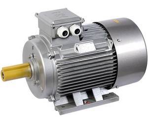
Let us now turn to the design of an induction motor. The rotor of an induction motor can conditionally be imagined also in the form of a copper cylinder. But in real constructions, this is a certain lattice in the form of a “squirrel cage” (Figure 1) made of copper or aluminum, combined with a magnetic circuit (lined iron).
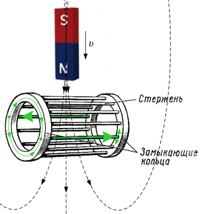
Figure 1. The rotor of an “squirrel cage” type induction motor with a current in one of the “squirrel cage” frames, which responds to an increase in an external magnetic field.
The figure schematically shows the flow of current in one of the "frames", i.e. in some bars of a squirrel cage, if you bring a magnet from above (create a current in the stator). In fact, the current in this case flows in all the rods, except, conditionally, the upper and lower rods, for which there is no change in flux (but they would react to a horizontally presented magnet).
Remember from the beginning of the last articlea picture with a schematic illustration of a two-phase synchronous machine, where was the magnet the rotor? Now let's make an induction motor out of it: instead of a magnet, we will put two perpendicular short-circuited coils, symbolizing the copper cylinder of the rotor (Figure 2).
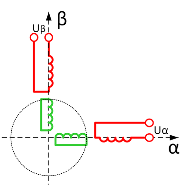
Figure 2. Schematic representation of a two-phase squirrel-cage induction motor.
Replacing a cylinder with two coils to explain the principle of operation (or modeling) is correct, just as it is correct to replace a three-phase winding with a two-phase one. Only in this case we replace ... the "infinite-phase winding" of the cylinder (an infinite number of frames) with two coils with equivalent inductance and resistance. After all, two coils can create exactly the same vector of current and magnetic flux as a cylinder.
And now let's make a short time out of an asynchronous machine synchronous. We feed the axis β into the coildirect current and wait two or three seconds until the response currents cease to flow in the rotor: “we will raise the external magnet”. That is, we wait for the currents to drop in the rotor so that the magnetic field of the stator “pierces the rotor” and no one interferes with it. What will happen now if you turn off the current in the stator? That's right, for the same two or three seconds, while the current of the rotor is opposed to this, we will get a “ordinary magnet” from the rotor (Figure 3).
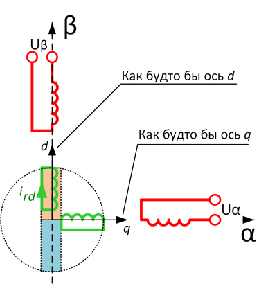
Figure 3. Asynchronous motor, when the direct current in phase β was just turned off - current flows in the rotor i rd .
What are we waiting for? Faster, until the magnet is gone, we draw along it the familiar d axis (as in a synchronous machine) and the q axis perpendicular to it , attached to the rotor. We turn on the vector control structure of the synchronous machine, apply current along the q axis , creating a moment, let's go!
So you can even really make a few revolutions until our sugar magnet has melted, and the d axisnot gone into oblivion. What to do? Let's not turn off the current along the d axis, feeding our magnet! And again, we’ll save the vector control structure of the synchronous machine by simply submitting the job along the d axis (there used to be zero). So, we look at Figure 4: the d , q axes are “attached” to the rotor by the position sensor, the motor is standing, the current along the d axis in the stator is applied , which in this case coincides with the β axis for a standing machine . There is no current along the q axis : we wait until the rotor “magnetizes”. And now we give current i sq (s - stator)! Go!
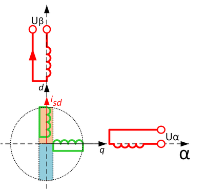
Figure 4. We apply current to the d axis , magnetizing the machine, preparing everything for supplying current to the stator axis q .
How far will we go with this method of Baron Munchausen? Unfortunately not. See what happened (Figure 5):

Figure 5. A magnet has slipped!
The engine began to spin, but some time after we applied current to the q axis , forming the total current i s and “nailed” this vector to the position of the rotor, the magnet in the rotor “moved out”! And stood exactly along the vector i s . The rotor does not understand where we drew the axes d , q ... It doesn’t matter to him whether it was spinning or not. It is important that its internal “induced magnet” ultimately wants to become co-directed with the magnetic flux of the stator, to “obey” the external flux. Due to the magnet that has moved out, the engine will stop spinning: not only is there no desired 90 degrees between the rotor magnet and the current i q , but also the axis currentd now pulls it in the opposite direction, compensating for the moment created by the current i q . The method of Baron Munchausen failed.
What to do with an elusive rotor magnet? And let's make the vector control structure of the induction motor not in the d , q axes attached to the rotor, but in other axes attached exactly to the current position of the “rotor magnet” - let's call them the x , y axes to distinguish them from d , q. According to the “scientific”, these are axes oriented along the rotor flux linkage. But how to find out where exactly now is the rotor flux linkage, i.e. where is the magnet in the rotor turned? Its position depends ... firstly, on the position of the rotor itself (we have a position sensor, well), secondly, on the stator currents (creating a stator current, which the rotor magnet is going to eventually rotate), and thirdly from the parameters of the rotor chain — the inductance and resistance of the “copper cylinder” (it’s a squirrel cage, it’s the rotor winding, it’s the rotor chain). Therefore ... knowing all this, the position of the “magnet” of the rotor can simply be calculated using several differential equations. This is done by the so-called rotor flux linking observer, highlighted in color on the final block diagram of the vector control of an asynchronous motor (Figure 6).
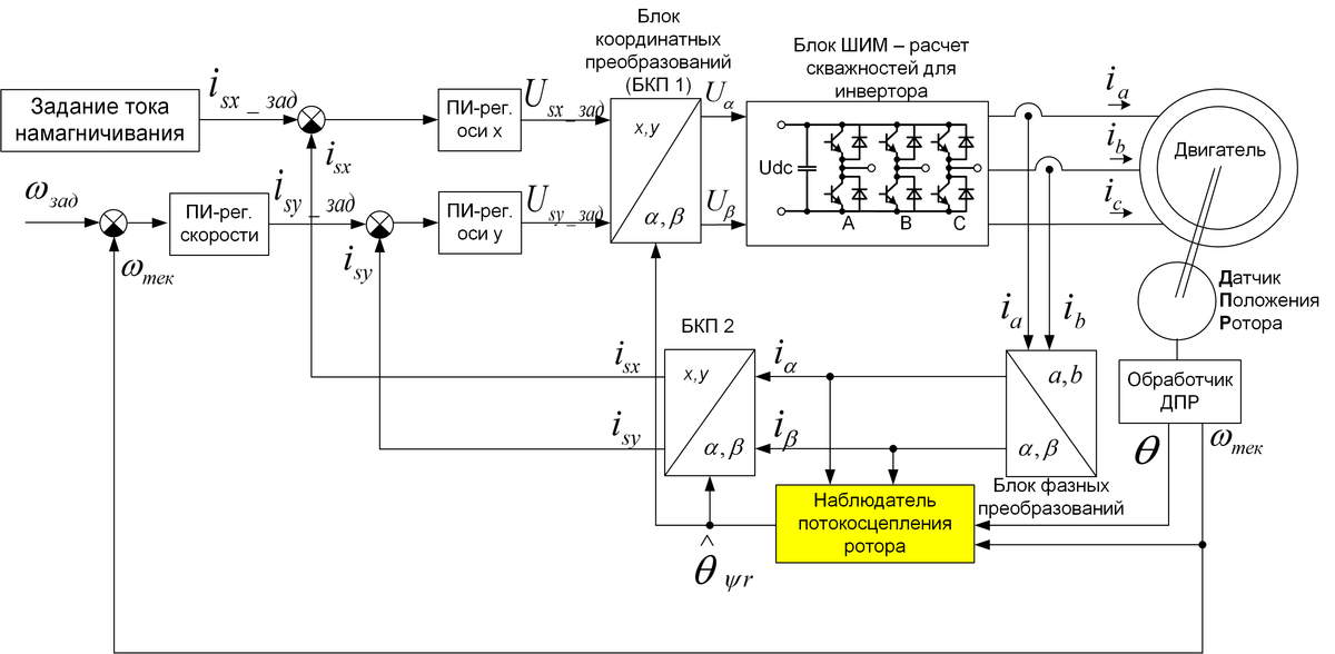
Figure 6. Vector sensor structure of asynchronous motor control.
The observer gets readings from the rotor position sensor, as well as the current stator currents in the α , β axes . The output of the observer is the position of the “magnet” of the rotor, namely the angle of the observed rotor flux linkage
 . Otherwise, the structure is completely similar to that for a synchronous machine, only the d , q axes are renamed to x , y , and the x axis is set to the current that will support our “magnet” in the rotor. Also, the index “ s”To show that this value relates to the stator, and not to the rotor. It should also be noted that in the Western literature the x , y axes are not used : for them, the d axis is always directed along the rotor field, which is for an asynchronous motor, and for a synchronous one. Back in Soviet times, our scientists separated the axes d , q and x , y , to avoid confusion: d , q are attached to the rotor, and x , y are attached to the rotor field.
 What turns out? The rotor magnet slides all the time, slides from the current position on the rotor towards the y axis current. The greater this current, the stronger the slip. The observer in real time calculates the position of this magnet and "twists" the x , y axes all the time forward with respect to the d , q axes (rotor position). The x axis always corresponds to the current position of flux linkage in the rotor - the position of the “magnet”. Those. x , y axisalways run (in motor mode) a little faster than the rotation of the rotor, compensating for the slip in it. The currents in the rotor, if measured or modeled, are sinusoidal. Only they change not with the frequency of stator currents, but with the frequency of this slip, i.e. very slow. If the stator of the industrial asynchronous is 50Hz, then when working under load, the current frequency in the rotor is units of hertz. That, in fact, is the whole secret of vector control for an induction motor.
How is vector control of an induction motor better than scalar? Scalar control is such when a voltage of a given frequency and amplitude is applied to the engine - for example, 380V 50Hz. And it does not depend on the load on the rotor - no current and vector controllers ... The voltage frequency and its amplitude are just set — scalar quantities, and let the currents and flows in the motor find a convenient place for themselves as they want. In the steady state engine operation, vector control is indistinguishable from scalar control - vector control will also apply the same, say, 380V, 50Hz at rated load. But in transient conditions ... if you need to quickly start the engine with a given moment, if you need to work out a motion diagram, if there is a pulse load,
In the vector structure, "everything is under control." The moment you set yourself, the flow too. You can limit them to the right level so as not to exceed the protection settings. It is possible to force the currents in a controlled manner if a short time is needed to make a several times larger moment. It is possible to regulate not only the motor torque, but also the flow ( x- axis current ): if the load on the motor is small, then there is no point in keeping the full flow in the rotor (making a magnet of “nominal mode”) - you can weaken it, reducing losses. It is possible to stabilize the speed with a speed controller with high accuracy and speed. You can use an asynchronous drive as a traction drive (in transport), setting the required traction moment. In general, for complex applications with dynamic motor operation, vector control of an induction motor is indispensable.
There are also distinctive features of vector control of an asynchronous motor from a synchronous one. The first is the position sensor. If for a synchronous drive we need to know the absolute position of the rotor in order to understand where the magnet is, then this is not required in an asynchronous drive. The rotor does not have any pronounced pole structure, the “magnet” in it constantly slides, and if you look at the formulas of the observer of the flux linkage of the rotor, then you do not need to know the position: only the rotor speed is included in the formulas (in fact, there are different formulas, but generally so). Therefore, you can save on the sensor: a conventional incremental encoder is enough to track the speed (or even a tachogenerator), absolute position sensors are not required. The second feature is flow control in an induction motor. In a synchronous machine with permanent magnets, the flow is not regulated, which limits the maximum engine speed: the voltage on the inverter ceases to be enough. In an induction motor, when this happens ... just decrease the axis referencex and move on! The maximum frequency is unlimited! Yes, the engine torque will decrease from this, but, most importantly, you can go “up”, unlike a synchronous machine (in truth, it is also possible there, but not far, not for all engines and with a lot of problems).
Similarly, there are sensorless vector control algorithms for an induction motor that estimate the rotor flux linkage angle without using the signal from the position (or speed) sensor of the rotor shaft. In the same way as for synchronous machines, there are problems in the operation of such systems at a low rotor speed, where the motor EMF is small.
You should also say a few words about the rotor. If for industrial asynchronous motors it is cheapened using an aluminum squirrel cage, then in traction, where weight and size indicators are more important, on the contrary, they can use a copper cylinder. So, in all your favorite Tesla electric vehicles, there is precisely an asynchronous electric motor with a copper rotor (Figure 7)
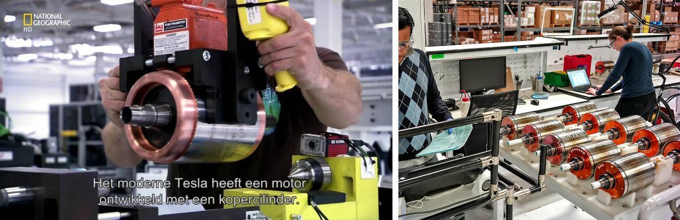
Figure 7. Tesla Model S asynchronous electric motor rotor in steel sheathing (photo from various sources for different years)
This, in fact, is all that I wanted to say about the asynchronous motor. This review article did not consider many subtleties, such as the rotor flux regulator, the possible construction of a vector structure in other coordinate axes, the mathematics of the rotor flux linkage observer, and much more. As at the end of the last article, for further details I refer the reader to modern books on the drive, for example, “Anuchin A. S. Electric drive control systems. MEI, 2015 " .
On which microcontroller you can make full-fledged vector control, read, for example, in the article “New domestic motor-control microcontroller K1921VK01T of OJSC“ NIIET ”, and how to debug it in the article “Methods for debugging microcontroller software in an electric drive” . Our company LLC NPF Vector also offers the development of custom-made control systems for electric motors and other electrical equipment, examples of completed projects can be found on our website .
PS
I apologize to the specialists for the not quite correct treatment with some terms, in particular with the terms “flux”, “flux linkage”, “magnetic field” and others - simplicity requires sacrifice ...