PPM-to-USB adapter on STM32F3Discovery, or We connect the aircraft model console to the computer as a HID joystick with STM32Cube
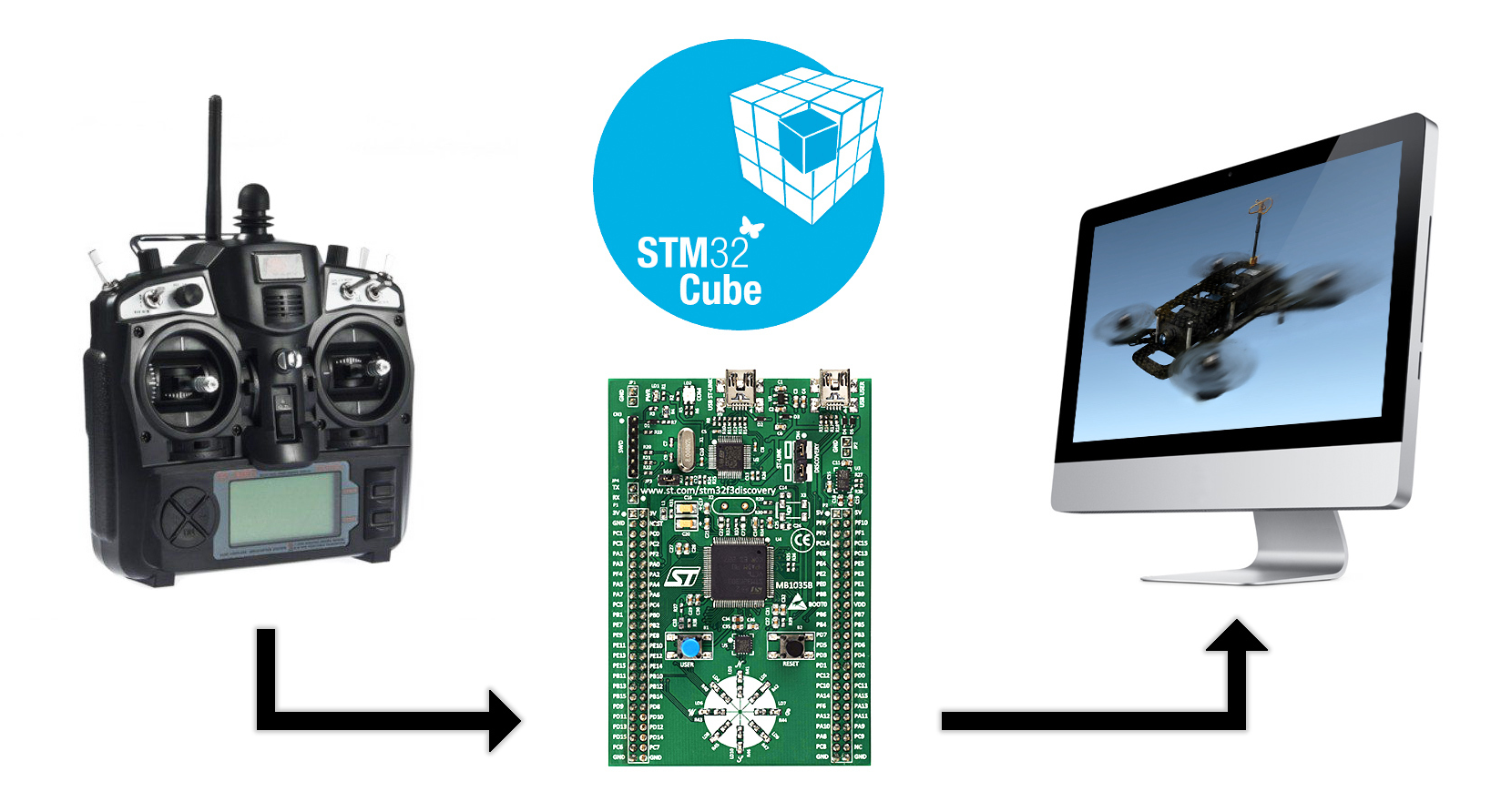
In this article I will tell you how:
- Create a project in STM32CubeMX and set up timers to capture external signals.
- Decode a PPM signal from an aircraft model console.
- Make Human Interface Device on STM32 and write your HID Report Descriptor.
- Fly in a simulator on a racing quadrocopter. :)
Foreword
Recently, FPV races on quadrocopters of the 250th class (FPV - First Person View) are gaining more and more popularity. The number 250 means the distance between the axes of the motors diagonally, typical of small maneuverable copters. Such devices are built on durable carbon frames that withstand falls and collisions. Propellers with a diameter of 5-6 inches with a large pitch (angle of inclination of the blades) are placed on powerful motors for the most dynamic flight. The image from the analog heading camcorder is transmitted at a frequency of 5.8 GHz to the monitor or video glasses of the pilot. Since digital transmission via WiFi creates a long delay (200-300 ms), the video is always broadcast on an analog channel. To record spectacular clips, action cameras are put on board (GoPro, Mobius, SJcam, Xiaomi Yi, etc.).
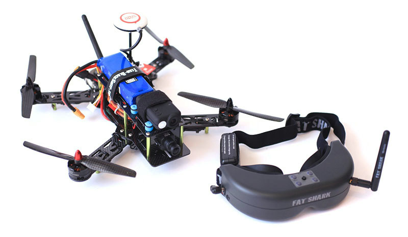
Here are some exciting videos about FPV copters:
Before building my own quadrocopter, I wanted to fly in a simulator and see if I would be interested in FPV races. For training, the FPV FreeRider simulator is well suited . It is inexpensive, has a free demo version and, according to experienced pilots, very accurately imitates the real mechanics of flight.
You can control the aircraft in the simulator from the keyboard or from the joystick. The keyboard is poorly suited for piloting, as the buttons can only transmit a discrete value (the button is pressed / not pressed) and it is impossible to transmit smoothly changing intermediate values. Joysticks from game consoles with analog sticks are much better, but they have a very small stick, which does not allow you to control the device quite accurately. An ideal option for a simulator is an aircraft model console connected to a computer through a special adapter, thanks to which the operating system sees it as a joystick.
I already had one quadrocopter, assembled for leisurely flights and photography, but too large and heavy for racing. Accordingly, there was a remote control - Turnigy 9X (in the first illustration). On the back side, it has a connector for an adapter to which the PPM signal is output. This signal is a short pulse with intervals from 1 to 2 milliseconds, the duration of which corresponds to the position of the controls (more about it in the section on decoding).
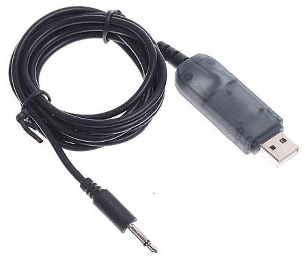
I must say that the adapters for connecting the remote control from PPM to USB have long been released and are being sold. A similar adapter in the flash drive form factor can be bought for $ 5 in China or a little more expensive in Russian stores. There are also open-source adapter projects on AVR controllers.
But an acute desire to fly immediately came to me late in the evening, when all Moscow aircraft model stores were already closed. I didn’t want to wait in the morning, there was no time to poison and solder the board with ATmega, so I decided to make a PPM-USB adapter on the STM32F3Discovery board, which had long been idle and was just at hand.
What is required
In order to make an adapter, you will need:
- Fee STM32F3Discovery . Any board with an STM32 that has a hardware USB ported on the board will do.
- A two-wire cable with a 3.5 mm mini-jack on one side (for Turnigy) and two BLS connectors, worn on the pins, on the other (for Discovery).
- STM32CubeMX code generator .
- IDE with a compiler for ARM. I am using Keil uVision 5 . The free demo version supports projects with executable code up to 32 kB, this is enough for our simple task.
- Turnigy 9X or any other with a PPM output. The project has also been successfully tested with the FlySky FS-i6.
Discovery debug boards are quite expensive. The described F3 costs about $ 20 and its capabilities are redundant for such a simple project. I used it because at the time of writing, this was the only board with hardware USB that I found at home. For those who have not bought it yet, I can advise you to pay attention to miniature boards with an STM32F103C8T6 controller from AliExpress for $ 3 and an ST-Link programmer from there. The process does not differ from that described in the article. Unless it is necessary to choose another controller at the beginning, indicate the presence of a quartz resonator and use a slightly different pinout.

Creating a project in STM32CubeMX
STM32Cube is a complex developed by STMicroelectronics in order to make life easier for developers of devices on STM32. It consists of the CubeMX graphics utility, HAL drivers, and Middleware components.
CubeMX is a tool for creating projects and initializing peripherals. To get started, just select the controller, check the boxes for the required modules, select the required modes in the menu and enter the desired values in several fields. CubeMX will generate the project and connect the necessary libraries to it. The device developer will only write the logic of the application.
HAL drivers(Hardware Abstraction Layer) are an API for working with modules and peripherals of the microcontroller. HAL allows you to separate the top layer of the application that the developer creates from working with registers and make the program code as portable as possible between the STM32 controller families.
Middlewares , or intermediate components, include the FreeRTOS operating system, a library for working with the file system, USB libraries, TCP / IP, etc.
It would seem that now it is possible to "program with the mouse" instead of manually writing bits to registers. But simplicity and convenience do not cancel the fact that you need to study the documentation, especially in cases where you need to squeeze the maximum speed, minimum power consumption or use peripherals in non-standard modes. STM32Cube does not yet cover 100% of all the capabilities of the microcontroller, but is approaching this. STMicroelectronics updates Cube from time to time, extends functions, and fix bugs. Therefore, if you already have Cube installed, check that it is the latest version.
Initial settings
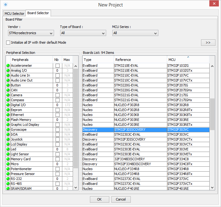
Work with the project begins with the choice of controller. Launch STM32CubeMX, click New Project . On the MCU Selector tab, you can select the desired controller from the filters. Since we have a finished debug board, on the Board Selector tab , we find STM32F3Discovery . After choosing a board, an image of the controller will appear with highlighted and signed pins.
There are four large tabs in the upper part of the window:
Pinout - for configuring the pin functions and presetting modules. We are on it at the moment.
Clock Configuration - clock setting, PLL, dividers.
Configuration - more detailed configuration of peripherals and middleware.
Power Consumption Calculator - calculation of the power consumed by the microcontroller.

In the left menu on the Pinout tab, you can use the desired peripherals, and on the controller circuit select a function for any of the outputs of the microcontroller. Some items on the left are warning icons. This means that the modules (in this case ADC, DAC, OPAMP2, RTC) can now be used incompletely, as some of their outputs are already occupied by other functions.
Configured pins are highlighted in green on the controller circuit. Since we chose not a bare controller without strapping, but a ready-made F3-Discovery debugging board, some of the outputs are already configured, for example, a blue button is connected to PA0, and LEDs to PE8 ... 15. Those pins to which some external devices are connected on Discovery are highlighted in orange, but the peripheral modules for them have not yet been configured. As you can see, these are pins for USB, quartz resonators, SPI and I2C for gyroscope and compass, DP and DM for USB. Gray conclusions are not currently used, any of them we can apply for our purposes.
Input selection
We are going to capture the duration of the pulses, which means the input must be connected to one of the channels of any timer. In addition, the signal level with Turnigy 9X is not 3.3V, like the supply voltage of the STM32, but 5V. We are too lazy to solder the voltage divider, so we need to choose an input that can withstand 5V (these inputs are called 5V-tolerant). Suitable pins can be found in the datasheet on STM32F303VCT6 in the Pinouts and Pin Description section . There are many timers in the STM32F3; they are scattered across almost all pins. A convenient option is PC6. It can withstand 5 volts and is located in the lower left corner of the board, next to GND. Assign the 1st channel of the 3rd timer TIM3_CH1 to this pin.
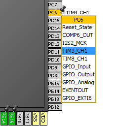
Clock setting
For the USB to work, the microcontroller must clock at a very stable frequency, which is why almost all USB devices have quartz resonators. The frequency stability of the built-in RC generator is not enough for USB. But on the STM32F3 Discovery board, developers for some reason were greedy and did not put quartz. However, if you carefully study the circuit , you can see that the MCO signal is connected to the input PF0-OSC_IN , where the quartz should be connected . It comes from the ST-Link programmer on the same board in which there is quartz. The User Manual for F3 Discovery (UM1570) in the OSC Clock section says that 8 MHz is being sent to this line.


Thus, the microcontroller is clocked from an external source. This mode is called Bypass. In the peripheral settings menu in the RCC section, for clocking High Speed Clock, select BYPASS Clock Source .

Before proceeding to a more detailed clock setting, we note in the peripheral menu that the microcontroller will act as a USB device.

Now you can go to the next big tab - Clock Configuration . Here we will see a huge diagram, which shows what clock signals are present in the microcontroller, where they come from, how they branch, multiply and divide. I highlighted in yellow those parameters that should be noted.
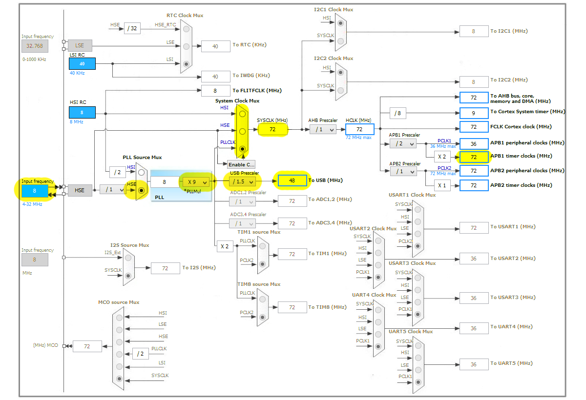
Check that the input frequencyInput Frequency is 8 MHz.
We set the PLL Source Mux switch to HSE (High Speed External) to clock from an external source rather than an internal source.
PLL - Phase Lock Loop, or PLL - phase-locked loop, is used to multiply the external frequency several times. Set the PLLMul multiplier to 9. Then we will reach the maximum possible frequency for the STM32F303 - 72 MHz.
The System Clock Mux must be in the PLLCLK position so that a multiplied frequency with PLL is used to clock the controller.
For the USB module, 48 MHz is needed, so put a 1.5 divider in front of USB.
Pay attention to the frequencyAPB1 timer clocks on the left side of the circuit. It goes to the timers and is useful to us in the future.
If any frequency is incorrectly configured, exceeds the maximum possible value or the switches are in an invalid position, then CubeMX will highlight this place in red.
Timer setting
To measure the pulse duration, we will start the TIM3 timer in the Input Capture mode. In the Reference Manual , under the section General-purpose timers (TIM2 / TIM3 / TIM4), there is a diagram illustrating the operation of timers. With colors, I highlighted the signals and registers used in Input Capture mode.
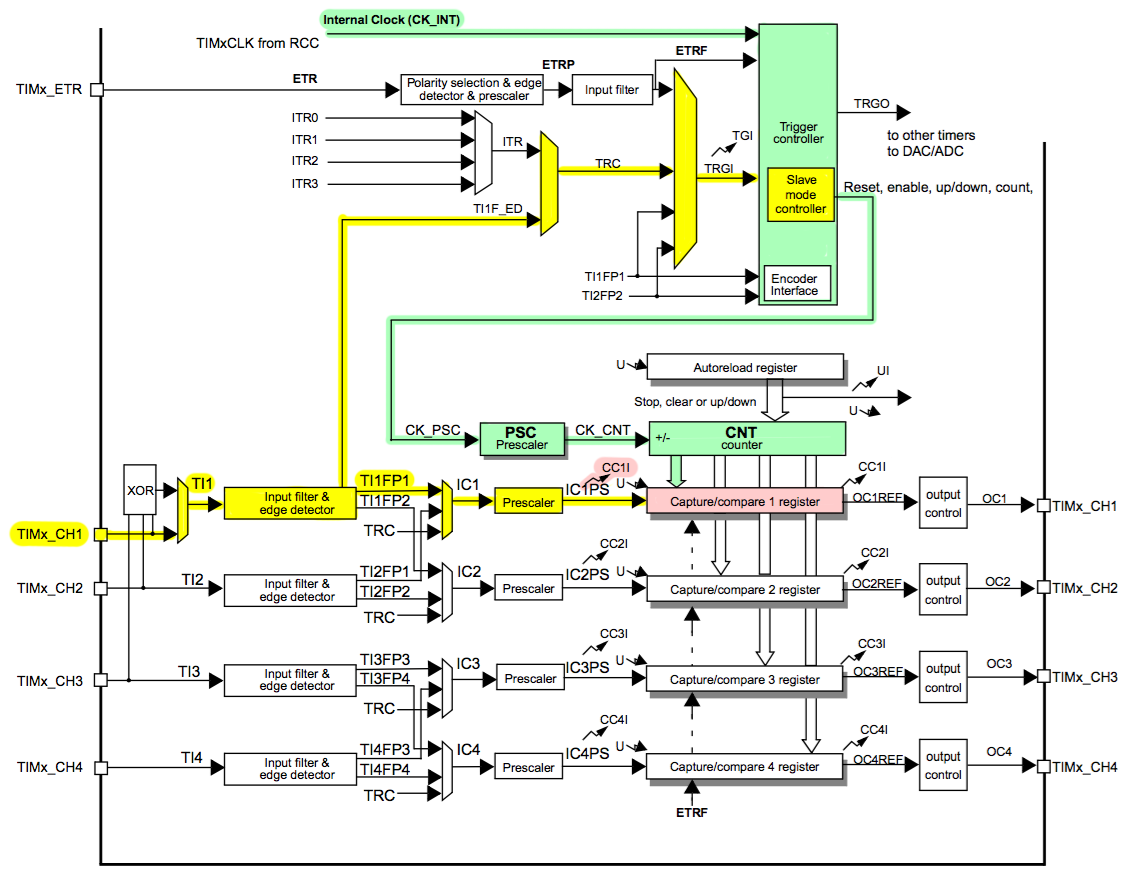
The clock signal highlighted in green continuously enters the CNT counter register and increments its value by 1 every clock cycle. In the Prescaler PSC divider, the clock frequency may decrease for a slower count.
An external signal is input to TIMx_CH1 . Edge detectorrecognizes edges of the input signal - transitions from 0 to 1 or from 1 to 0. When registering the edge, it gives two commands highlighted in yellow:
- a command to write the value of the CNT counter to the Capture / compare 1 register (CCR1) register and call the CC1I interrupt .
- a command for Slave mode controller , according to which the CNT value is reset to 0 and the countdown starts again.
Here is an illustration of the process in a timeline:

When an interrupt occurs, we will perform actions with the captured value. If the input pulses come too often, and the actions that occur in the interrupt handler are too long, then the value of CCR1 can be overwritten before we read the previous one. In this case, you need to check the Overcapture flag or apply DMA (Direct Memory Access) when the data from CCR1 automatically fills the prepared array in memory. In our case, the shortest pulse has a duration of 1 millisecond, and the interrupt handler will be simple and short, so do not worry about overwriting. Go
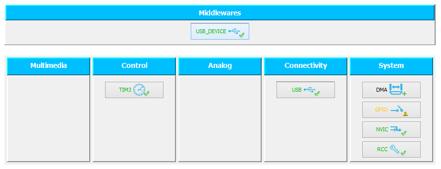
back to the Pinout tab and set the TIM3 timer in the Peripherals menu .
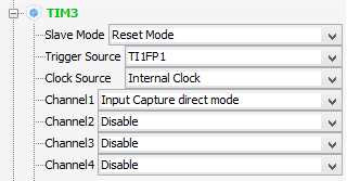
Slave Mode: Reset Mode- means that at some event the timer will be reset to 0.
Trigger Source: TI1FP1 - the event used to reset and start the timer is the signal edge captured from TI1 input.
ClockSource: Internal Clock - the timer is clocked from the internal generator of the microcontroller.
Channel 1: Input Capture direct mode - capture intervals from the 1st channel in the CCR1 register.
On the next large Configuration tab, we will make additional timer settings.
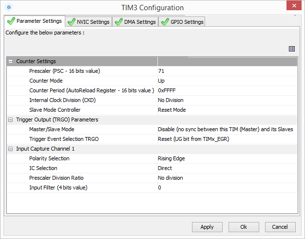
Prescaler is a timer divider. If it is 0, the frequency is taken directly from the clock bus APB clock - 72 MHz. If prescaler is 1, the frequency is divided by 2 and becomes 36 MHz. Set the divisor to 71 so that the frequency is divided by 72. Then the timer frequency will be 1 MHz and the intervals will be measured with a resolution of 1 microsecond.
Counter Period - set the maximum possible 16-bit value 0xFFFF. The period is important for generating time slots, for example, for PWM. But the period is not important for signal capture; we will make it known to be large for any input pulses.
Polarity Selection: Falling Edge - timer values will be captured on the falling edge of the input signal.
On the NVIC Settings tab, put a dawTIM3 global interrupt so that an interrupt is generated during events associated with the 3rd timer.
USB device setup
We have already noted that the controller will be a USB device. Since the joystick belongs to the class of HID devices, in the Middlewares -> USB_DEVICE menu, select Class For FS IP: Human Interface Device Class (HID) . Then CubeMX will connect libraries for the HID device to the project.

Let's go to the USB_DEVICE settings on the Configuration tab in the Middlewares section :
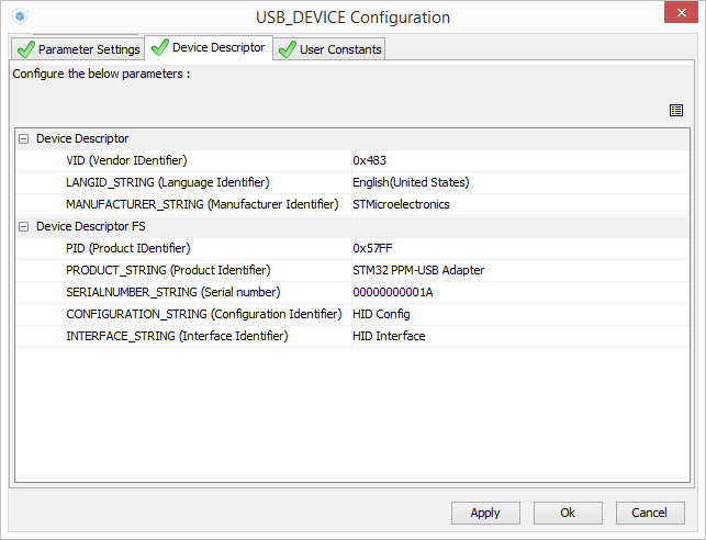
Vendor ID and Product ID are two 16-bit identifiers that are unique to each model of USB device. VID corresponds to the device manufacturer, and each manufacturer assigns PID, guided by their own considerations. I could not find the official list of VID and PID, I only found the identifier database supported by enthusiasts. To get your own Vendor ID, you need to go to the USB Implementers Forum on usb.org and pay a few thousand dollars. Small companies or open-source developers who can’t afford their VID can request a USB chip manufacturer and officially receive a VID / PID pair for their project. Such a service is offered, for example, by FTDI or Silicon Laboratories.
If you connect two devices with the same VID / PID, but of a different type (for example, one is a HID device and the other is Mass Storage), the operating system will try to install the same driver for them, and at least one of them will not work. That is why VID / PID pairs for different device models must be unique.
Since we are not making a device for ourselves, we are not going to sell and distribute it, we will leave VID 0x0483, corresponding to STMicroelectronics, and we’ll come up with our own PID. By default, CubeMX offers PID 0x5710 for the HID device. Replace it, for example, with 0x57FF.
Replace the Product string with the STM32 PPM-USB Adapter. This name will appear in the list of devices in the Windows Control Panel. We will not change the serial number (S \ N) yet.
When Windows detects it detects a device with a combination of VID, PID, and S \ N that it has not seen before, the system installs the appropriate driver for it. If the combination of VID, PID and S \ N has already been used, then Windows automatically substitutes the previously used driver. You can see this, for example, when you connect the flash drive to USB. The first time connecting and installing takes some time. On subsequent connections, the drive starts working almost instantly. However, if you connect another instance of the Flash drive of the same model, but with a different serial number, the system will install a new driver for it, even though it has the same VID and PID.
I will explain why this is important. If you created a USB mouse on your STM32 with your VID, PID and S \ N, connected it to the computer, and then made a USB joystick without changing the VID, PID and S \ N, then Windows will perceive the new device as a mouse that already used in the system, and will not install the joystick driver. Accordingly, the joystick will not work. Therefore, if you want to change the type of your device, leaving the VID / PID unchanged, be sure to change its serial number.
Project Generation for IDE
The last settings you need to make are the project generation settings. This is done through Project -> Settings ... There we will set the name, destination folder and the desired IDE, under which CubeMX will create the project. I chose MDK-ARM V5 , because I use Keil uVision 5. On the Code Generator tab, you can check the Copy only the necessary library files box so that the project is not cluttered with unnecessary files.
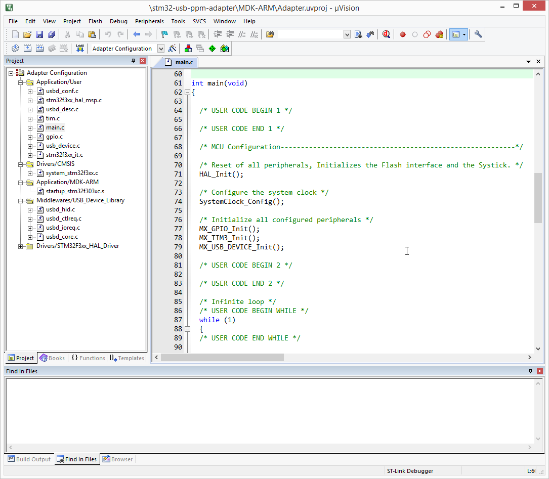
Press the button Project -> Generate code . CubeMX will create a project with a code that can be opened in Keil uVision and compiled and flashed without additional settings. In the main.c file in the main (void) functionFunctions for initializing clock, ports, timer, and USB have already been inserted. In them, the microcontroller modules are configured in accordance with the modes that we set in CubeMX.
In the code, constructions of this kind are often found:
/* USER CODE BEGIN 0 */
(...)
/* USER CODE END 0 */
It is assumed that the user will embed their code in these sections. If the Keep User Code when re-generating option is enabled in the CubeMX project settings , then the code enclosed between these lines will not be overwritten during the secondary generation of an existing project. Unfortunately, only sections created by CubeMX are saved. Sections / * USER CODE * / created by the user will be lost. Therefore, if after writing the code in the IDE you want to return to CubeMX and generate the project again with the new settings, I recommend making a backup copy of the project.
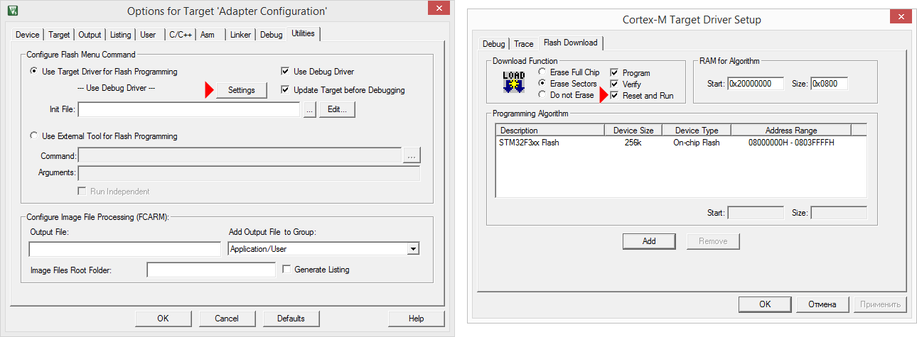
In the firmware settings in uVision ( Flash -> Configure Flash Tools ) I advise you to enable the Reset after flash optionso that the microcontroller starts immediately after flashing. By default, it is disabled, and after each flashing, you have to press the Reset button on the board.
PPM decoding
PPM - Pulse Position Modulation - a method of encoding transmitted signals, very widespread in aircraft model electronics. It is a sequence of pulses, the time intervals between which correspond to the transmitted numerical values.
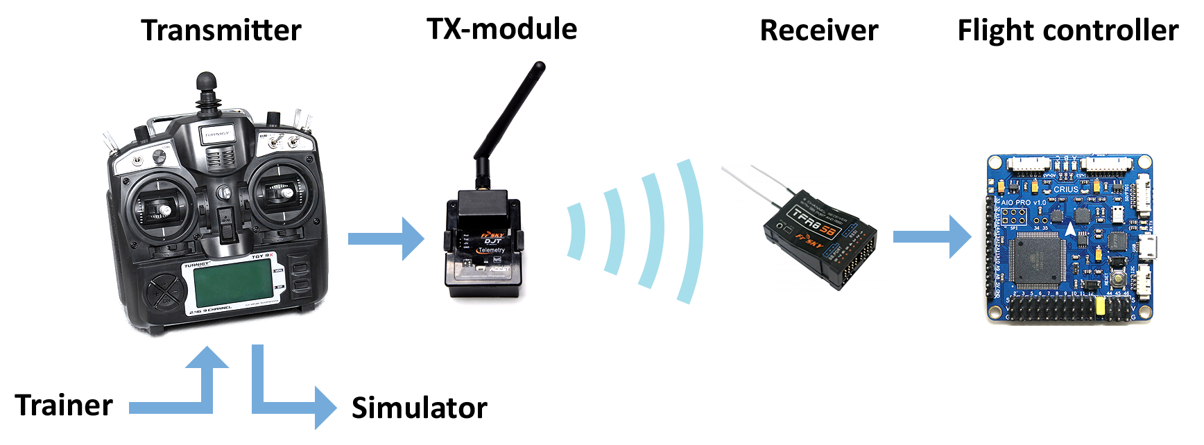
According to this protocol, the console sends information to the transmitting radio module, which is inserted into the console at the back. Many receivers that are placed on board the copter can transmit control signals for the flight controller via PPM. In addition, almost any console has connectors for connecting a second console in the trainer-student mode and for connecting the console to a simulator, which also usually use PPM.
Let's record a signal from the simulated output of Turnigy 9X with a logic analyzer:

Each sequence encodes the current state of the controls on the remote. Usually the first four values (they are also called channels) correspond to the position of analog sticks, and the subsequent ones to the position of toggle switches or potentiometers.
The minimum position of the control corresponds to an interval of 1000 μs, the maximum - 2000 μs, the average position - 1500 μs. Bursts of pulses, or frames, are separated by significantly longer intervals and follow with a period of 20–25 ms.
Let's take a closer look at the signal:

As you can see, three sticks are in the neutral position (1, 3, 4), and one is in the extreme position (2). Three toggle switches are off (5, 6, 7), and the last is on (8). The microcontroller, acting as an adapter, must capture this sequence, add the values to an array and send it via USB as a command from the joystick. Let's write a pulse sequence decoder.
Capture Interruption
After initialization in main.c, before the main while loop, start the TIM3 timer in Input Capture capture mode from channel 1, with the generation of capture interruptions. To do this, use the corresponding function from HAL:
HAL_TIM_IC_Start_IT(&htim3, TIM_CHANNEL_1);
The htim3 structure declared in main.c is the TIM3 timer handler, which contains all the structures and variables associated with the timer: parameters for initialization, pointers to all timer registers (counter value, divider, all settings, interrupt flags), pointer on a handler DMA that works with this timer, etc. The developer does not need to look for which bits in which register are responsible for what and manually set and reset them. It is enough to pass the handler to the HAL function. HAL libraries will do the rest themselves.
HAL structure principles are described in more detail in the Description of STM32F3xx HAL drivers document.(UM1786). It should be noted that the HAL libraries themselves are well documented. To understand how the HAL works for the timer and how to use it, you can read the comments in the stm32f3xx_hal_tim.h and stm32f3xx_hal_tim.c files .
For each interrupt that the TIM3 timer generates, the TIM3_IRQHandler handler is called . It is in the stm32f3xx_it.c file , in turn, the HAL_TIM_IRQHandler handler , standard for all timers, is called in it, and a pointer to the htim3 structure is passed to it.
void TIM3_IRQHandler(void)
{
  /* USER CODE BEGIN TIM3_IRQn 0 */
  /* USER CODE END TIM3_IRQn 0 */
  HAL_TIM_IRQHandler(&htim3);
  /* USER CODE BEGIN TIM3_IRQn 1 */
  /* USER CODE END TIM3_IRQn 1 */
}
If we look inside HAL_TIM_IRQHandler file stm32f3xx_hal_tim.c , we see a huge handler that checks the interrupt flags for timer causes callback-function and clears the flag after execution. If a capture event occurs , it calls the HAL_TIM_IC_CaptureCallback function . It looks like this:
__weak void HAL_TIM_IC_CaptureCallback(TIM_HandleTypeDef *htim)
{
/* NOTE : This function Should not be modified, when the callback is needed, the __HAL_TIM_IC_CaptureCallback could be implemented in the user file
*/
}
This means that we can override this function in main.c . Therefore, insert this callback before the int main (void) function :
void HAL_TIM_IC_CaptureCallback(TIM_HandleTypeDef *htim)
{
};
I would like to see how the interrupt is performed. Add to it the quick on-off of one of the conclusions:
void HAL_TIM_IC_CaptureCallback(TIM_HandleTypeDef *htim)
{
  HAL_GPIO_WritePin(GPIOE, GPIO_PIN_8, GPIO_PIN_SET);
  __nop();__nop();__nop();__nop();__nop();__nop();
  HAL_GPIO_WritePin(GPIOE, GPIO_PIN_8, GPIO_PIN_RESET);
};
The PE8 pin has already been initialized as an output. Between switching on and off, __nop () instructions are inserted , which forms a delay of 1 clock cycle. This is done so that my $ 8 Chinese logic analyzer running at 24 MHz does not miss a too short pulse from a 72 MHz microcontroller. Now compile the project Project -> Build target and flash the controller Flash -> Download . We’ll connect the PPM from the remote to PC6, and see what happens on PC6 and PE8 with the analyzer.

Callback is really called at the right moments - right after the input signal has transitioned from 1 to 0. Therefore, everything was done correctly.
Capture and process captured data
We’ll edit the callback so that it will add each captured value to the captured_value buffer without changes. If the timer captures a very large value (more than 5000 μs), this means that a pause was recorded, the packet was received in its entirety and it can be processed. The processed values are added to the rc_data array of 5 elements. In the first four, the stick positions are reduced to the range [0; 1000], in the fifth, individual bits are set in accordance with the toggle switches, which will be interpreted as pressing buttons on the gamepad.
uint16_t captured_value[8] = {0};
uint16_t rc_data[5] = {0};
uint8_t pointer = 0;
uint8_t data_ready = 0;
...
void HAL_TIM_IC_CaptureCallback(TIM_HandleTypeDef *htim)
{
    uint8_t i;
    uint16_t temp;
    // считываем значение из регистра захвата
    temp = HAL_TIM_ReadCapturedValue(htim, TIM_CHANNEL_1);
    // если интервал слишком длинный, значит, пакет принят
    if ((temp > 5000) && (!data_ready))
    {
        pointer = 0;
        // приводим четыре значения со стиков к диапазону [0;1000]
        for (i = 0; i < 4; i++)
        {
            if (captured_value[i] < 1000)
                captured_value[i] = 1000;
            else if (captured_value[i] > 2000)
                captured_value[i] = 2000;
            rc_data[i] = captured_value[i]-1000;
        };
        // записываем положения тумблеров как биты
        rc_data[4] = 0;
        if (captured_value[4] > 1500)
            rc_data[4] |= (1<<4);
        if (captured_value[5] > 1500)
            rc_data[4] |= (1<<5);
        if (captured_value[6] > 1500)
            rc_data[4] |= (1<<6);
        if (captured_value[7] > 1500)
            rc_data[4] |= (1<<7);
        data_ready = 1;
    }
    else // сохраняем одно принятое значение в буфер
    {
        captured_value[pointer] = temp;
        pointer++;
    };
    if (pointer == 8) // защита от переполнения
        pointer = 0;
}
I will explain why I placed the bits corresponding to the buttons, not in the lower 4 bits, but in bits five through eight. In the simulator, it is supposed to connect a gamepad from Xbox, where the LB, RB, Start and Back buttons are used, and they have numbers from 5 to 8.
In the main loop, the data_ready flag will be continuously rotated, by which data will be sent to the computer.
while (1)
{
  if (data_ready)
  {
    // здесь будет отправка данных на ПК
    data_ready = 0;
  }
}
To check how this works, connect the remote control, compile and flash it again, and then start debugging Debug -> Start / Stop Debug Session .
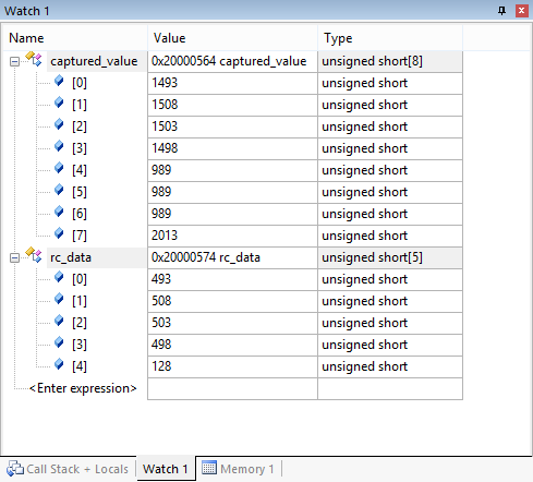
Open the window for tracking variables View -> Watch Windows -> Watch 1 and add captured_value and rc_data there .
We start the debugging with the Debug -> Run command and in real time, without even adding breakpoints, we will see how numbers change after the sticks.
Next, you need to send data to the computer in the form of a joystick command.
Configure HID device and create HID Report Descriptor
USB HID (Human Interface Device) is a class of devices for human-computer interaction. These include keyboards, mice, joysticks, gamepads, touch panels. The main advantage of HID devices is that they do not require special drivers in any operating system: Windows, OS X, Android, and even iOS (via the USB-Lightning adapter). A detailed description can be found in the document Device Class Definition for HID . The main thing we need to know to create a PPM-USB adapter is what HID Report and HID Report Descriptor are .
The HID device sends byte packets to the computer in a predefined format. Each such package is a HID Report. The device informs the computer about the data format when it connects, sending a HID Report Descriptor, a packet description that indicates how many bytes the packet contains and the purpose of each byte and bit in the packet. For example, the HID Report of a simple mouse consists of four bytes: the first byte contains information about the buttons pressed, the second and third bytes contain the relative movement of the cursor along X and Y, and the fourth byte contains the rotation of the scroll wheel. Report Descriptor is stored in the device controller memory as an array of bytes.

Before creating a descriptor, I would like to dwell separately on terminology. Two terms are common in the English language environment - joystick and gamepad . The word joystick is usually called a manipulator that is held with one hand and tilted in different directions, and gamepad is a device with buttons and sticks that is held with two hands. Russian-speaking users usually call the joystick both of them. In the description of the HID device, there is a difference between the joystick and the gamepad. The aircraft model console is more similar in its functional purpose to a gamepad, so in the future I will sometimes use the term “gamepad”.
We generated a project, indicating that the device will act as a Human Interface Device. This means that a USB HID library is connected to the project and a Device Descriptor has already been generated. It is located in the usbd_hid.c file , describes the mouse report and looks like this:
HID_Mouse_Report_Descriptor
__ALIGN_BEGIN static uint8_t HID_MOUSE_ReportDesc[HID_MOUSE_REPORT_DESC_SIZE]  __ALIGN_END =
{
  0x05,   0x01,
  0x09,   0x02,
  0xA1,   0x01,
  0x09,   0x01,
  0xA1,   0x00,
  0x05,   0x09,
  0x19,   0x01,
  0x29,   0x03,
  0x15,   0x00,
  0x25,   0x01,
  0x95,   0x03,
  0x75,   0x01,
  0x81,   0x02,
  0x95,   0x01,
  0x75,   0x05,
  0x81,   0x01,
  0x05,   0x01,
  0x09,   0x30,
  0x09,   0x31,
  0x09,   0x38,
  0x15,   0x81,
  0x25,   0x7F,
  0x75,   0x08,
  0x95,   0x03,
  0x81,   0x06,
  0xC0,   0x09,
  0x3c,   0x05,
  0xff,   0x09,
  0x01,   0x15,
  0x00,   0x25,
  0x01,   0x75,
  0x01,   0x95,
  0x02,   0xb1,
  0x22,   0x75,
  0x06,   0x95,
  0x01,   0xb1,
  0x01,   0xc0
};
Creating HID Report Descriptor manually is extremely time-consuming. To facilitate the task, there is a tool called the HID Descriptor Tool (DT). This program can create a descriptor for your device. In the archive with it you can find several examples of descriptors for different devices.
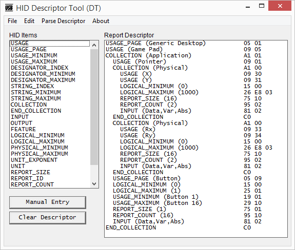
Here is a very good article about creating your own HID descriptor for mouse and keyboard (in English). I will tell you in Russian how to make a handle for a gamepad.
The HID-Report sent by the console must contain four 16-bit values for two axes of analog sticks and 16 one-bit values for buttons. Total 10 bytes. Its handle created in DT will look like this:
    0x05, 0x01,                    // USAGE_PAGE (Generic Desktop)
    0x09, 0x05,                    // USAGE (Game Pad)
    0xa1, 0x01,                    // COLLECTION (Application)
    0x09, 0x01,                    //   USAGE (Pointer)
    0xa1, 0x00,                    //   COLLECTION (Physical)
    0x09, 0x30,                    //     USAGE (X)
    0x09, 0x31,                    //     USAGE (Y)
    0x15, 0x00,                    //     LOGICAL_MINIMUM (0)
    0x26, 0xe8, 0x03,              //     LOGICAL_MAXIMUM (1000)
    0x75, 0x10,                    //     REPORT_SIZE (16)
    0x95, 0x02,                    //     REPORT_COUNT (2)
    0x81, 0x02,                    //     INPUT (Data,Var,Abs)
    0xc0,                          //   END_COLLECTION
    0xa1, 0x00,                    //   COLLECTION (Physical)
    0x09, 0x33,                    //     USAGE (Rx)
    0x09, 0x34,                    //     USAGE (Ry)
    0x15, 0x00,                    //     LOGICAL_MINIMUM (0)
    0x26, 0xe8, 0x03,              //     LOGICAL_MAXIMUM (1000)
    0x75, 0x10,                    //     REPORT_SIZE (16)
    0x95, 0x02,                    //     REPORT_COUNT (2)
    0x81, 0x02,                    //     INPUT (Data,Var,Abs)
    0xc0,                          //   END_COLLECTION
    0x05, 0x09,                    //   USAGE_PAGE (Button)
    0x19, 0x01,                    //   USAGE_MINIMUM (Button 1)
    0x29, 0x10,                    //   USAGE_MAXIMUM (Button 16)
    0x15, 0x00,                    //   LOGICAL_MINIMUM (0)
    0x25, 0x01,                    //   LOGICAL_MAXIMUM (1)
    0x75, 0x01,                    //   REPORT_SIZE (1)
    0x95, 0x10,                    //   REPORT_COUNT (16)
    0x81, 0x02,                    //   INPUT (Data,Var,Abs)
    0xc0                           // END_COLLECTION
It looks no less intimidating than a mouse descriptor. But if you understand what each line means, everything turns out to be quite understandable and logical.
USAGE shows how the system should interpret data that goes further.
There are a lot of Usage types, they are sorted into groups - Usage Pages. Therefore, in order to select a specific Usage, you must first refer to the corresponding USAGE_PAGE. About what Usage can be found in the Hid Usage Tables document . At the very beginning of the descriptor, we indicate that the joystick will be described:
USAGE_PAGE (Generic Desktop)
USAGE (Game Pad)
COLLECTION combines several related datasets.
Physical Collection is used for data related to one specific geometric point, for example, one analog stick. Application Collection is used to combine different functions in one device. For example, a keyboard with an integrated trackpad may have two Application Collection. We describe only the joystick, which means that the collection will be one:
COLLECTION (Application)
...
END_COLLECTION
After that, you need to specify that the elements that transmit the coordinates will be described. Usage Pointer is used to describe mice, joysticks, gamepads, digitizers:
USAGE (Pointer)
The following are descriptions of analog sticks combined in a collection:
COLLECTION (Physical)USAGE (X)END_COLLECTION
USAGE (Y)
LOGICAL_MINIMUM (0)
LOGICAL_MAXIMUM (1000)
REPORT_SIZE (16)
REPORT_COUNT (2)
INPUT (Data,Var,Abs)
USAGE here indicates that the deviation values are used along two axes - X and Y.
LOGICAL_MINIMUM and LOGICAL_MAXIMUM specify within which limits the transmitted value can vary.
REPORT_COUNT and REPORT_SIZE set, respectively, how many numbers and what size we are going to transfer, namely two 16-bit numbers.
INPUT (Data, Var, Abs) means that the data comes from the device to the computer, and these data can change. The values in our case are absolute. For example, relative values come from the mouse to move the cursor. Sometimes data is described as Const, not Var. This is necessary to transmit non-significant bits. For example, in a mouse report with three buttons, 3 bits of Var for buttons and 5 bits of Const are transmitted to supplement the transfer size to one byte.
As you can see, the descriptions of the X and Y axes are grouped together. They have the same size, the same limits. The same analog stick could be described as follows, describing each axis individually. Such a descriptor will work similarly to the previous one:
COLLECTION (Physical)USAGE (X)
LOGICAL_MINIMUM (0)
LOGICAL_MAXIMUM (1000)
REPORT_SIZE (16)
REPORT_COUNT (1)
INPUT (Data, Var, Abs)USAGE (Y)END_COLLECTION
LOGICAL_MINIMUM (0)
LOGICAL_MAXIMUM (1000)
REPORT_SIZE (16)
REPORT_COUNT (1)
INPUT (Data, Var, Abs)
After the first stick, the second analog stick is described. Its axes have a different Usage so that you can distinguish them from the first stick - Rx and Ry:
COLLECTION (Physical)USAGE (Rx)END_COLLECTION
USAGE (Ry)
LOGICAL_MINIMUM (0)
LOGICAL_MAXIMUM (1000)
REPORT_SIZE (16)
REPORT_COUNT (2)
INPUT (Data, Var, Abs)
Now you need to describe a few buttons of the gamepad. This can be done as follows:
USAGE_PAGE (Button)
USAGE (Button 1)
USAGE (Button 2)
USAGE (Button 3)
...
USAGE (Button 16)
The cumbersome recording of buttons of the same type can be reduced by using the Usage range:
USAGE_PAGE (Button)
USAGE_MINIMUM (Button 1)
USAGE_MAXIMUM (Button 16)
The data transmitted by the buttons are 16 single-bit values, varying from 0 to 1:
LOGICAL_MINIMUM (0)
LOGICAL_MAXIMUM (1)
REPORT_SIZE (1)
REPORT_COUNT (16)
INPUT (Data,Var,Abs)
The order of the lines in the descriptor is not strict. For example, Logical_Minimum and Logical_Maximum can be written before Usage (Button), or the lines Report_Size and Report_Count can be swapped.
It is important that before the Input command all the necessary parameters for data transmission are located (Usage, Mimimum, Maximum, Size, Count).
When the descriptor is formed, it can be checked with the Parse Descriptor command for errors.
If everything is in order, then export it with the extension h. The file usbd_hid.c replace the handle to the new and will adjust in usbd_hid.h size descriptor HID_MOUSE_REPORT_DESC_SIZE from 74 to 61.
The reports are sent to the flag data_ready . For this tomain.c we include the header file usbd_hid.h and in the main loop we call the function for sending the report. The rc_data array is of type uint16, so the pointer to it must be cast to an 8-bit type and pass size 10 instead of 5.
#include "usbd_hid.h"
...
while (1)
{
  if (data_ready)
  {
    USBD_HID_SendReport(&hUsbDeviceFS, (uint8_t*)rc_data, 10);
    data_ready = 0;
  };
};
We compile the project and flash it again.
Connection and use
Reconnect the USB cable from the ST-LINK USB connector to the USER USB connector. Windows will detect the new device and automatically install the driver. Let's go to the Control Panel -> Devices and Printers and see our STM32 USB-PPM Adapter device with a gamepad icon.
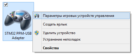
In the device settings, you can see how the cross moves across the field and the columns move after the sticks are moved, and the button symbols light up from the toggle switch. Calibration is not necessary because the minimum and maximum values have already been set in the descriptor.

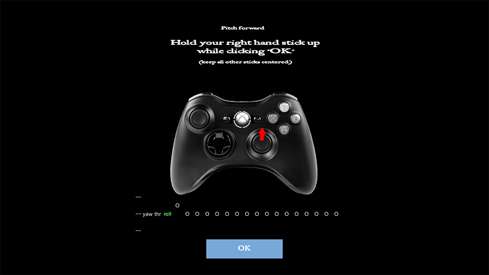
Starting FPV FreeRider, we will see how on the main screen on the drawn virtual gamepad the sticks move in accordance with our remote control. If axes are not assigned correctly for some reason, you can reconfigure them in the Calibrate Controller section .
The toggle switches corresponding to the buttons on the remote control are used to switch flight modes (acrobatic / stabilized), switch the camera view (from board / from the ground), start the flight from the beginning or turn on the race for a while.
Flew!
On the video - the result of several days of my training. While I'm flying with horizon auto-leveling, and not in acrobatic mode, as all masters of FPV racing do. In acro mode, if you release the sticks, the copter does not automatically return to the horizontal position, but continues to fly at the same angle as it flew. Managing in acro mode is much more difficult, but you can achieve greater speed, maneuverability, make upheavals in the air and even fly upside down.
To Charpu MastersI am still very far away, but I continue training and I can say for sure that the idea of a racing mini-copter interested me even more. And soon, I will definitely be engaged in its construction and flights no longer in the simulator, but in harsh reality, with real crashes, broken propellers, broken engines and burned out batteries. But this is a topic for other articles :)
The project for Keil uVision 5 and STM32CubeMX rests on GitHub .
