Laser location, Doppler imaging and aperture synthesis
Angular resolution is the most important characteristic of any telescopic system. Optics claims that this resolution is unambiguously related to the wavelength at which the observation is carried out and to the diameter of the input aperture of the telescope. With large diameters, as you know, a big problem. It is unlikely that a telescope will ever be built more than this .
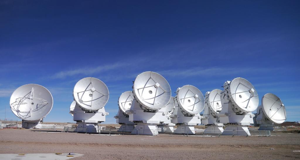
One of the ways to significantly increase the resolution is the method used in radio astronomy and radar for synthesizing large and super large apertures. In the millimeter range, the largest aperture - 14 km - is promised to be formed by the 66th antennas of the ALMA project in Chile.
The transfer of aperture synthesis methods to the optical region, where wavelengths are several orders of magnitude shorter than that of radars, is associated with the development of laser heterodyning techniques .
1. Physical fundamentals of image formation.
It will not be a mistake to say that the image in any optical device is formed by diffraction of light at the input aperture, and nothing more. Let's look at the image of the object from the center of the aperture. The angular distribution of the image brightness of an infinitely distant point source of light (as, indeed, of any other) will be the same for an equal diameter lens and pinhole camera. The difference between a lens and a pinhole is only that the lens transfers the image formed by its aperture from infinity to its focal plane. Or, to put it another way, produces a phase transformation of the input plane wave front into a spherically converging one. For a remote point source and a circular aperture, an image is a well-known Airy picture with rings .

The angular size of the Airy disk can, in principle, be reduced, and as if increasing the resolution ( according to the Rayleigh criterion ), if the aperture is fixed in a special way. There is such a distribution of transmission over the radius, in which the central disk can theoretically be made arbitrarily small. However, the light energy is redistributed along the rings and the contrast of the complex image drops to zero.
From a mathematical point of view, the procedure for generating a diffraction image reduces to a two-dimensional Fourier transform from the input light field (in the scalar approximation, the field is described by a complex function of coordinates and time). Any image recorded by the eye, screen, matrix, or other quadratic in intensity receiver is nothing more than a two-dimensional amplitude spectrum of the limited by the aperture of the light field emitted by the object. It is easy to get the same Airy picture if you take a square matrix of the same complex numbers (simulating a flat wavefront from a distant point), “cut” a round “aperture” out of it, zeroing out the edges, and making the Fourier transform of the entire matrix.
In short, if you somehow record the field (synthesize the aperture) on a sufficiently large area without loss of amplitude and phase information, then to obtain an image you can do without giant mirrors of modern telescopes and megapixel matrices, simply calculating the Fourier transform of the resulting data array.
2. Satellite location and super resolution.
We will observe a stabilized object moving across the line of sight illuminated by a continuous coherent laser source. The radiation reflected from it is recorded by a heterodyne photodetector with a small aperture. Recording a signal over time t is equivalent to implementing a one-dimensional aperture of length vt, where v is the tangential velocity of the object. It is easy to evaluate the potential resolution of such a method. Let's look at a near-Earth satellite in the upper elongation, flying at an altitude of 500 km at a speed of 8 km / s. In 0.1 seconds of recording the signal, we get a “one-dimensional telescope” of 800 meters in size, theoretically capable of viewing in the visible range satellite parts of a millimeter fraction. Not bad for such a distance.
Of course, the reflected signal at such distances decreases by many orders of magnitude. However, heterodyne reception (coherent mixing with reference radiation) largely compensates for this attenuation. Indeed, as you know, the output photocurrent of the receiver in this case is proportional to the product of the amplitudes of the reference radiation and the incoming signal. We will increase the proportion of reference radiation and thereby amplify the entire signal.
You can look from the other side. The spectrum of the recorded signal from the photodetector is a set of Doppler components, each of which is the sum of the contributions from all points of the object that have the same radial velocity. The one-dimensional distribution of reflecting points on an object determines the frequency distribution of spectral lines. The resulting spectrum is essentially a one-dimensional “image” of the object along the “Doppler shift” coordinate. Two points of our satellite, located at a distance of 1 mm from each other in a plane perpendicular to the line of sight, have a radial velocity difference of the order of 0.01-0.02 mm / s. (The ratio of this difference to satellite speed is equal to the ratio of the distance between points to the distance to the satellite). The difference of the Doppler frequencies of these points for a visible wavelength of 0.5 microns will be (f = 2V / λ) of the order of 100 Hz. The spectrum (Doppler image) from the entire microsatellite, say, 10 cm in size, will fit into the 10 kHz range. It is a measurable quantity.
You can see from the third side. This technology is nothing more than a hologram record, i.e. interference pattern arising from the mixing of the reference and signal fields. It contains the amplitude and phase information sufficient to restore the complete image of the object.
Thus, illuminating the satellite with a laser, registering the reflected signal and mixing it with the reference beam from the same laser, we obtain a photocurrent on the photodetector, whose time dependence reflects the structure of the light field along the “one-dimensional aperture”, the length of which, as has already been said, can be made big enough.
A two-dimensional aperture, of course, is much better and more informative. Let us arrange evenly several photodetectors across the satellite’s motion and thus write the reflected field over the area vt * L, where L is the distance between the extreme photodetectors, which in principle is unlimited. For example, the same 800 meters. Thus, we synthesize the aperture of the “two-dimensional telescope” 800 * 800 meters in size. The resolution along the transverse coordinate (L) will depend on the number of photodetectors and the distance between them, on the other, the “time” coordinate (vt) - on the laser emission bandwidth and the sampling frequency of the signal from the photodetector.
So, we have a recorded light field over a very large area and can do anything with it. For example, to obtain a two-dimensional image of very small objects at a very large distance without any telescopes. Or you can restore the three-dimensional structure of an object by digitally refocusing in range.
Of course, the real three-dimensional configuration of the reflecting points on the object does not always coincide with their "Doppler" distribution over radial velocities. Coincidence will be if these points are in the same plane. But in the general case, a lot of useful information can be extracted from the "Doppler image".
3. What happened before.
American DARPA funded the SALTI program some time ago, the essence of which was the implementation of such technology. It was supposed to locate objects on the ground (tanks, for example) with an ultra-high resolution from a flying plane, some encouraging data were obtained. However, this program was either closed or classified in 2007 and since then nothing has been heard about it. Something was done in Russia too. Here it is possible to see the image obtained at a wavelength of 10.6 microns.
4. Difficulties in technical implementation at a wavelength of 1.5 microns.
Upon mature thought, I decided not to write anything here. Too many problems.
5. Some primary results.
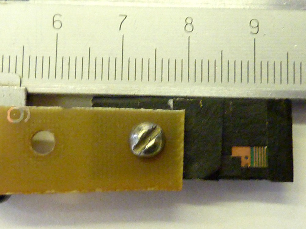
So far, it has been difficult to “examine” from a distance of 300 meters the details of a flat diffusely reflecting metal object measuring 6 by 3 mm. It was a piece of some printed circuit board, here is the photo:
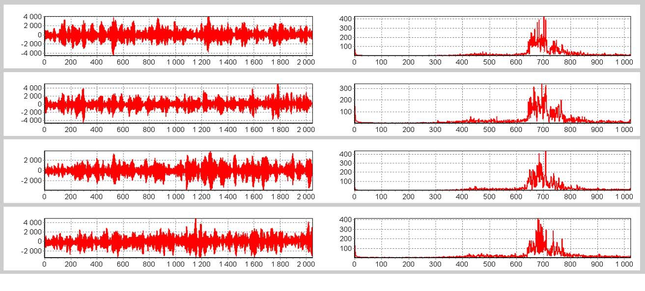
The object rotated around an axis perpendicular to the line of sight, registration of the reflected signal occurred at about the moment of maximum reflection (glare). The laser spot illuminating the object was about 2 cm in size. Only 4 photodetectors were used, spaced 0.5 meters apart. The size of the synthesized aperture is estimated at 0.5 m per 10 m.
Actually, just in case, the recorded signals themselves (left) and their spectra (right) in relative units:
From the previous photo of the object, photoshop highlighted only the illuminated and reflecting areas of interest to us, which are required see:
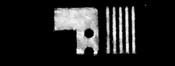
Image reconstructed by a two-dimensional Fourier transform of 4 signals and scaled for comparison:

This image actually consists of only 4 lines (and about 300 columns), the vertical resolution of the image, respectively, is about 0.5 mm, but the dark corner and both are round holes seem to be visible. The horizontal resolution is 0.2 mm, such is the width of the conductive tracks on the board, all five pieces are visible. (An ordinary telescope must be two meters in diameter to see them in the near infrared).
In truth, the resolution obtained is still far from the theoretical limit, so it would be nice to bring this technology to mind. The devil, as you know, is in the details, but there are a lot of details.
Thanks for attention.
One of the ways to significantly increase the resolution is the method used in radio astronomy and radar for synthesizing large and super large apertures. In the millimeter range, the largest aperture - 14 km - is promised to be formed by the 66th antennas of the ALMA project in Chile.
The transfer of aperture synthesis methods to the optical region, where wavelengths are several orders of magnitude shorter than that of radars, is associated with the development of laser heterodyning techniques .
1. Physical fundamentals of image formation.
It will not be a mistake to say that the image in any optical device is formed by diffraction of light at the input aperture, and nothing more. Let's look at the image of the object from the center of the aperture. The angular distribution of the image brightness of an infinitely distant point source of light (as, indeed, of any other) will be the same for an equal diameter lens and pinhole camera. The difference between a lens and a pinhole is only that the lens transfers the image formed by its aperture from infinity to its focal plane. Or, to put it another way, produces a phase transformation of the input plane wave front into a spherically converging one. For a remote point source and a circular aperture, an image is a well-known Airy picture with rings .
The angular size of the Airy disk can, in principle, be reduced, and as if increasing the resolution ( according to the Rayleigh criterion ), if the aperture is fixed in a special way. There is such a distribution of transmission over the radius, in which the central disk can theoretically be made arbitrarily small. However, the light energy is redistributed along the rings and the contrast of the complex image drops to zero.
From a mathematical point of view, the procedure for generating a diffraction image reduces to a two-dimensional Fourier transform from the input light field (in the scalar approximation, the field is described by a complex function of coordinates and time). Any image recorded by the eye, screen, matrix, or other quadratic in intensity receiver is nothing more than a two-dimensional amplitude spectrum of the limited by the aperture of the light field emitted by the object. It is easy to get the same Airy picture if you take a square matrix of the same complex numbers (simulating a flat wavefront from a distant point), “cut” a round “aperture” out of it, zeroing out the edges, and making the Fourier transform of the entire matrix.
In short, if you somehow record the field (synthesize the aperture) on a sufficiently large area without loss of amplitude and phase information, then to obtain an image you can do without giant mirrors of modern telescopes and megapixel matrices, simply calculating the Fourier transform of the resulting data array.
2. Satellite location and super resolution.
We will observe a stabilized object moving across the line of sight illuminated by a continuous coherent laser source. The radiation reflected from it is recorded by a heterodyne photodetector with a small aperture. Recording a signal over time t is equivalent to implementing a one-dimensional aperture of length vt, where v is the tangential velocity of the object. It is easy to evaluate the potential resolution of such a method. Let's look at a near-Earth satellite in the upper elongation, flying at an altitude of 500 km at a speed of 8 km / s. In 0.1 seconds of recording the signal, we get a “one-dimensional telescope” of 800 meters in size, theoretically capable of viewing in the visible range satellite parts of a millimeter fraction. Not bad for such a distance.
Of course, the reflected signal at such distances decreases by many orders of magnitude. However, heterodyne reception (coherent mixing with reference radiation) largely compensates for this attenuation. Indeed, as you know, the output photocurrent of the receiver in this case is proportional to the product of the amplitudes of the reference radiation and the incoming signal. We will increase the proportion of reference radiation and thereby amplify the entire signal.
You can look from the other side. The spectrum of the recorded signal from the photodetector is a set of Doppler components, each of which is the sum of the contributions from all points of the object that have the same radial velocity. The one-dimensional distribution of reflecting points on an object determines the frequency distribution of spectral lines. The resulting spectrum is essentially a one-dimensional “image” of the object along the “Doppler shift” coordinate. Two points of our satellite, located at a distance of 1 mm from each other in a plane perpendicular to the line of sight, have a radial velocity difference of the order of 0.01-0.02 mm / s. (The ratio of this difference to satellite speed is equal to the ratio of the distance between points to the distance to the satellite). The difference of the Doppler frequencies of these points for a visible wavelength of 0.5 microns will be (f = 2V / λ) of the order of 100 Hz. The spectrum (Doppler image) from the entire microsatellite, say, 10 cm in size, will fit into the 10 kHz range. It is a measurable quantity.
You can see from the third side. This technology is nothing more than a hologram record, i.e. interference pattern arising from the mixing of the reference and signal fields. It contains the amplitude and phase information sufficient to restore the complete image of the object.
Thus, illuminating the satellite with a laser, registering the reflected signal and mixing it with the reference beam from the same laser, we obtain a photocurrent on the photodetector, whose time dependence reflects the structure of the light field along the “one-dimensional aperture”, the length of which, as has already been said, can be made big enough.
A two-dimensional aperture, of course, is much better and more informative. Let us arrange evenly several photodetectors across the satellite’s motion and thus write the reflected field over the area vt * L, where L is the distance between the extreme photodetectors, which in principle is unlimited. For example, the same 800 meters. Thus, we synthesize the aperture of the “two-dimensional telescope” 800 * 800 meters in size. The resolution along the transverse coordinate (L) will depend on the number of photodetectors and the distance between them, on the other, the “time” coordinate (vt) - on the laser emission bandwidth and the sampling frequency of the signal from the photodetector.
So, we have a recorded light field over a very large area and can do anything with it. For example, to obtain a two-dimensional image of very small objects at a very large distance without any telescopes. Or you can restore the three-dimensional structure of an object by digitally refocusing in range.
Of course, the real three-dimensional configuration of the reflecting points on the object does not always coincide with their "Doppler" distribution over radial velocities. Coincidence will be if these points are in the same plane. But in the general case, a lot of useful information can be extracted from the "Doppler image".
3. What happened before.
American DARPA funded the SALTI program some time ago, the essence of which was the implementation of such technology. It was supposed to locate objects on the ground (tanks, for example) with an ultra-high resolution from a flying plane, some encouraging data were obtained. However, this program was either closed or classified in 2007 and since then nothing has been heard about it. Something was done in Russia too. Here it is possible to see the image obtained at a wavelength of 10.6 microns.
4. Difficulties in technical implementation at a wavelength of 1.5 microns.
Upon mature thought, I decided not to write anything here. Too many problems.
5. Some primary results.
So far, it has been difficult to “examine” from a distance of 300 meters the details of a flat diffusely reflecting metal object measuring 6 by 3 mm. It was a piece of some printed circuit board, here is the photo:
The object rotated around an axis perpendicular to the line of sight, registration of the reflected signal occurred at about the moment of maximum reflection (glare). The laser spot illuminating the object was about 2 cm in size. Only 4 photodetectors were used, spaced 0.5 meters apart. The size of the synthesized aperture is estimated at 0.5 m per 10 m.
Actually, just in case, the recorded signals themselves (left) and their spectra (right) in relative units:
From the previous photo of the object, photoshop highlighted only the illuminated and reflecting areas of interest to us, which are required see:
Image reconstructed by a two-dimensional Fourier transform of 4 signals and scaled for comparison:
This image actually consists of only 4 lines (and about 300 columns), the vertical resolution of the image, respectively, is about 0.5 mm, but the dark corner and both are round holes seem to be visible. The horizontal resolution is 0.2 mm, such is the width of the conductive tracks on the board, all five pieces are visible. (An ordinary telescope must be two meters in diameter to see them in the near infrared).
In truth, the resolution obtained is still far from the theoretical limit, so it would be nice to bring this technology to mind. The devil, as you know, is in the details, but there are a lot of details.
Thanks for attention.