Porting Lode Runner from BC to UKNC
In March-May of this year, I spent several weeks (in the evenings and on weekends) on porting the Lode Runner toy from BK-0010 to the UKSC.
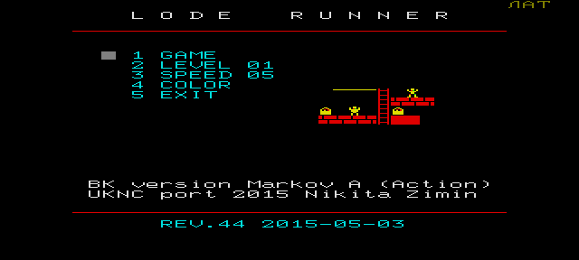
Screenshot of the ported menu:
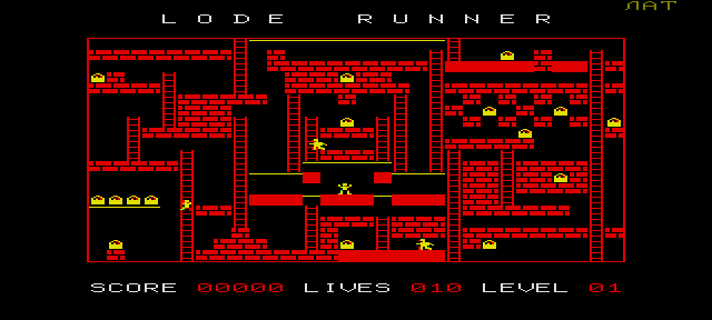
Game screen of the ported version:
BK-0010 is a household computer of the late 1980s and early 1990s, and partly a school computer (KUVT-86 classes). UKSC is a school computer of the 1990s. BC and UKSC are partially compatible in architecture and command system - both computers date back to the PDP-11 family.
Until this year, I did not write anything serious under the UKSC, but I had to understand the machine code. There was a desire to write something, but usually I have big problems with free time, so it would hardly work out from scratch. And for starters, it's better to take the task easier. When porting, the amount of work is usually much less than when writing from scratch - you encounter mainly problems of incompatibility between the two systems.
At the zx.pk.ru forum (one of the sites where fans of retrocomputing in general and PDP-11 compatible machines in particular hang out), the hobot participant praised the Lode Runner implementation on the BC - this was actually the reason, for a start I tried to “look” at the toy code , well, got involved.
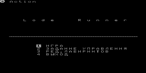
Original version menu:
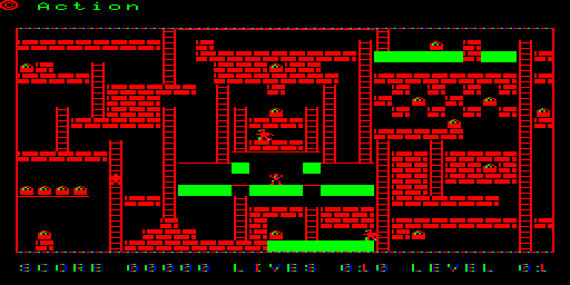
The game screen of the original version (on the color monitor):
A couple of weeks in the evenings and weekends I spent time analyzing and disassembling. In the emulator, BKBTL added the ability to collect a trace - that is, each instruction is disassembled and saved to a text file.
I make a run of the section that interests me with recording the trace, then I turn off the trace (sort & uniq) - I get fragments of the logic. I add comments to this, I gradually get a common file.
It sounds simple, but in fact it is a rather complicated work based on conjectures and their confirmation or refutation. For example, we look that the address 001756 before the start of the game gets the value 10, then it is decremented, when it reaches 0, the game ends - apparently, this is the number of lives. We find confirmation of this, we place comments on the text where this address occurs. This is a fairly simple example, in more complex cases I spent a lot of time figuring out what was happening.
When the received volume became quite large (40+ KB of text, more than 1,500 lines) and I figured out at least in general terms what was happening, how it was stored and displayed - I began to think how to translate it to the UKSC.
Here you can look at the final listing resulting from the disassembly:
github.com/nzeemin/uknc-loderunner/blob/master/original/loderunner.lst
Each labyrinth is 20 lines of 30 blocks, a total of 600 blocks.
The block type is encoded by a number from 0 to 7 - three bits, triplet. For one 16-bit word, 5 complete triplets are obtained.
When working with PDP-11 like machines, an 8-decimal system is widely used, therefore it is quite convenient to use triplets.
As a result, each maze fits into 240 bytes.
Block Types:
The sprites of these objects are arranged in the order of numbering of block types. When a labyrinth is decoded, at the same time a “labyrinth image” is created in the memory (by byte per block), and the initial state of the labyrinth is drawn on the screen.
On the BC, the screen is addressed directly by memory access, the lines go one after the other, in fact it is a “framebuffer”, and I would say that this is great - very convenient for programming graphics. Line BC - 256 color pixels, 64 bytes per line. But how many pixels in a row depends on how you connected the monitor:
if it is in black and white, then it is 512 b / w pixels in a row (1 bit per pixel, 8 pixels per byte),
and if it is for color output , then this is 256 color pixels per line (2 bits per pixel, 4 pixels per byte).
At the UKSC, the screen organization is completely different, and much more complicated. The screen lies in three blocks of memory, three “plans”. And each pixel is three bits, a bit in each plane - we get 8 colors. At the UKSC we have several video modes - 640 × 288, 320 × 288, 160 × 288, more precisely, we always have exactly 288 lines and you can apply your own divider to each individual line, getting different horizontal resolutions. For the central processing unit (CPU), screen plans are not directly accessible, only through access to the ports. Moreover, only two out of three plans are available for the CPU.
In this case, the 320 × 288 mode suited me well - the line is obtained in 320 color pixels 80 bytes long in each of the three plans. If you use two plans, then the pixels are also four-color - almost like on a BC.
I began to write examples in assembler of the UKSC and was a little depressed - because the “compiled - linked - launched” cycle is rather slow. The problem is in the tools. There is a cross-assembler MACRO11, although it is somewhat buggy. But there is no cross-linker. But fortunately, not so long ago Patron posted the console RT-11: zx-pk.ru/showthread.php?t=24755 - in fact it is an emulator of a PDP11-compatible machine that interacts with the OS command line as with a terminal. Thus, it became possible to compile and link the native means of RT-11. This I consider a real breakthrough, dramatically accelerated the work.
After that, things went well, I made a drawing of the playing field frame, rendering sprites, figured out how to mix the bits in the sprites (I wrote a program in C # to mix them), then in blocks I began to transfer the code from the shared file with disasma to the new sources. I took a memory dump from the BC, allocated a block where the levels are, RT11 utility DUMP made a textbook for the levels.
First, I transferred a block of code that displays the level, on this I debugged the output of sprites. Then he began to transfer game logic. Those. in general, the transfer is almost one-to-one, with the exception of places where the screen goes. Therefore, there are places in the logic that I don’t understand how they work (the same AI hell), but it doesn’t matter - the main thing is that they work.
As a result, by the beginning of May (when the main work absorbed me again), a working option was obtained, although without sound.
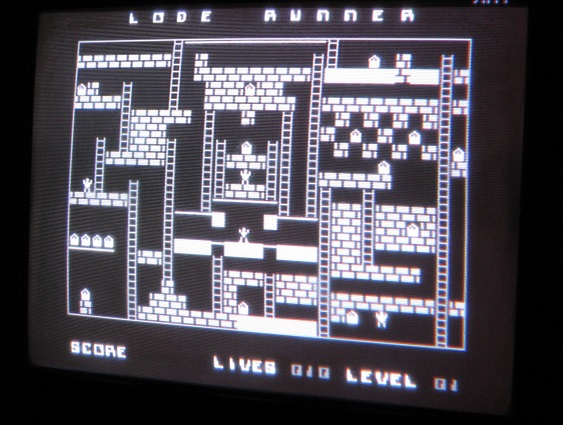
Photo of a working game on a real machine (thanks hobot):
Screenshot of the ported menu:

Game screen of the ported version:

BK-0010 is a household computer of the late 1980s and early 1990s, and partly a school computer (KUVT-86 classes). UKSC is a school computer of the 1990s. BC and UKSC are partially compatible in architecture and command system - both computers date back to the PDP-11 family.
Game selection
Until this year, I did not write anything serious under the UKSC, but I had to understand the machine code. There was a desire to write something, but usually I have big problems with free time, so it would hardly work out from scratch. And for starters, it's better to take the task easier. When porting, the amount of work is usually much less than when writing from scratch - you encounter mainly problems of incompatibility between the two systems.
At the zx.pk.ru forum (one of the sites where fans of retrocomputing in general and PDP-11 compatible machines in particular hang out), the hobot participant praised the Lode Runner implementation on the BC - this was actually the reason, for a start I tried to “look” at the toy code , well, got involved.
Original version menu:

The game screen of the original version (on the color monitor):

Reverse engineering
A couple of weeks in the evenings and weekends I spent time analyzing and disassembling. In the emulator, BKBTL added the ability to collect a trace - that is, each instruction is disassembled and saved to a text file.
I make a run of the section that interests me with recording the trace, then I turn off the trace (sort & uniq) - I get fragments of the logic. I add comments to this, I gradually get a common file.
It sounds simple, but in fact it is a rather complicated work based on conjectures and their confirmation or refutation. For example, we look that the address 001756 before the start of the game gets the value 10, then it is decremented, when it reaches 0, the game ends - apparently, this is the number of lives. We find confirmation of this, we place comments on the text where this address occurs. This is a fairly simple example, in more complex cases I spent a lot of time figuring out what was happening.
When the received volume became quite large (40+ KB of text, more than 1,500 lines) and I figured out at least in general terms what was happening, how it was stored and displayed - I began to think how to translate it to the UKSC.
Here you can look at the final listing resulting from the disassembly:
github.com/nzeemin/uknc-loderunner/blob/master/original/loderunner.lst
Labyrinth
Each labyrinth is 20 lines of 30 blocks, a total of 600 blocks.
The block type is encoded by a number from 0 to 7 - three bits, triplet. For one 16-bit word, 5 complete triplets are obtained.
When working with PDP-11 like machines, an 8-decimal system is widely used, therefore it is quite convenient to use triplets.
As a result, each maze fits into 240 bytes.
Block Types:
;	0 -- пусто
;	1 -- сплошная стена
;	2 -- кирпичная стена
;	3 -- верёвка
;	4 -- чёрт
;	5 -- человек
;	6 -- сундук
;	7 -- лестница
The sprites of these objects are arranged in the order of numbering of block types. When a labyrinth is decoded, at the same time a “labyrinth image” is created in the memory (by byte per block), and the initial state of the labyrinth is drawn on the screen.
Screen Organization
On the BC, the screen is addressed directly by memory access, the lines go one after the other, in fact it is a “framebuffer”, and I would say that this is great - very convenient for programming graphics. Line BC - 256 color pixels, 64 bytes per line. But how many pixels in a row depends on how you connected the monitor:
if it is in black and white, then it is 512 b / w pixels in a row (1 bit per pixel, 8 pixels per byte),
and if it is for color output , then this is 256 color pixels per line (2 bits per pixel, 4 pixels per byte).
At the UKSC, the screen organization is completely different, and much more complicated. The screen lies in three blocks of memory, three “plans”. And each pixel is three bits, a bit in each plane - we get 8 colors. At the UKSC we have several video modes - 640 × 288, 320 × 288, 160 × 288, more precisely, we always have exactly 288 lines and you can apply your own divider to each individual line, getting different horizontal resolutions. For the central processing unit (CPU), screen plans are not directly accessible, only through access to the ports. Moreover, only two out of three plans are available for the CPU.
In this case, the 320 × 288 mode suited me well - the line is obtained in 320 color pixels 80 bytes long in each of the three plans. If you use two plans, then the pixels are also four-color - almost like on a BC.
Synthesis
I began to write examples in assembler of the UKSC and was a little depressed - because the “compiled - linked - launched” cycle is rather slow. The problem is in the tools. There is a cross-assembler MACRO11, although it is somewhat buggy. But there is no cross-linker. But fortunately, not so long ago Patron posted the console RT-11: zx-pk.ru/showthread.php?t=24755 - in fact it is an emulator of a PDP11-compatible machine that interacts with the OS command line as with a terminal. Thus, it became possible to compile and link the native means of RT-11. This I consider a real breakthrough, dramatically accelerated the work.
After that, things went well, I made a drawing of the playing field frame, rendering sprites, figured out how to mix the bits in the sprites (I wrote a program in C # to mix them), then in blocks I began to transfer the code from the shared file with disasma to the new sources. I took a memory dump from the BC, allocated a block where the levels are, RT11 utility DUMP made a textbook for the levels.
First, I transferred a block of code that displays the level, on this I debugged the output of sprites. Then he began to transfer game logic. Those. in general, the transfer is almost one-to-one, with the exception of places where the screen goes. Therefore, there are places in the logic that I don’t understand how they work (the same AI hell), but it doesn’t matter - the main thing is that they work.
As a result, by the beginning of May (when the main work absorbed me again), a working option was obtained, although without sound.
Photo of a working game on a real machine (thanks hobot):

References
- zx-pk.ru/showthread.php?t=24886 - thread on this topic on zx.pk.ru
