Novelty for RepRap or auto-leveling right on target
An important feature in 3D printing using FDM technology is the precise setting of the gap between the surface (table) on which the printed model is being erected and the extruder nozzle from which molten plastic is fed. If this gap is larger than necessary, then the first layer of molten plastic may simply not stick to the table and instead of the finished model you will get a lump of plastic hanging on the extruder. If the gap is very small or completely absent, then in the best case you will get incorrect model dimensions in height and thickening of the model in the lower part adjacent to the table. At worst, printing just won't start. The feed gear will groove the groove on the plastic thread or the plastic thread will bend between the hot end and the feed gear and unwind past).
To install this gap, there are several technical (and not so) solutions. For example:
- Placing a sheet of paper, and setting the starting point until the paper begins to move between the nozzle and the table with a slight effort.
- Using a micro switch that is pressed when the extruder approaches the table. Instead of a micro switch, an optical sensor is sometimes used, which also adds a little accuracy to the measurements.
- Capacitive proximity sensor.
But they all have flaws. The micro switch and the capacitive sensor are removed at a certain distance from the extruder nozzle, and also require height calibration relative to the level of the extruder. A sheet of paper, to put it mildly, is not technological, and with its help it is impossible to use the auto-poor functionality (measuring the curvature of the table).
On my Prusa Mendel i2, it was constantly necessary to set the height of the first layer after printing lasting more than an hour. And when the printer is idle, I had to adjust the height again. I suppose that during long-term operation of the printer, the structure warmed up and changed its size, thereby increasing the height of the first layer. Because after long work it was necessary to reduce the height, and after cooling, increase it.
Applying such a self-leveling device, I completely got rid of “dancing with a tambourine” near the printer when printing the first layer.
I suggest that the "rugged" owners of 3D printers repeat my decision.
I have developed and successfully tested on a Prusa Mendel i2 printer, a more accurate method for setting the distance between the extruder nozzle and the table. Which is based on measuring the pressure force of the extruder nozzle to the table using a strain gauge. Experienced users and CNC designers will say that this method has already been tested and the error of such a measurement will depend on the ambient temperature, but believe me (to my word, until you read to the end), this solution does not depend on temperature.
To repeat the design, not so much
is needed: - Strain gauge.
- Signal amplifier with ADC.
- 3D printer and some plastic to print some structural elements.
The first 2 points are "penny": in China, 200 rubles. (04.16.2015) or in Russia, naturally more expensive. And the presence or acquisition in the near future of the third paragraph is confirmed by the fact that you are still reading this text.
The time required to complete the printer is no more than one evening. Of course, not counting the time spent printing fasteners using a 3D printer.
And now for the details.
For the prototype, I used a load cell from Chinese household kitchen scales, but analogues of such sensors can be purchased in Russia.
What is a load cell and how does it work?
Strain gauge (strain gauge; from Latin tensus - stress) - a sensor that converts the strain to a convenient signal for measurement (usually electric):
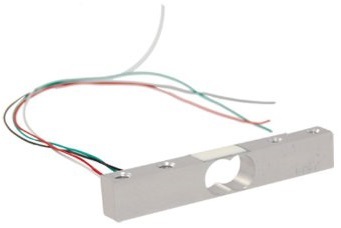
The sensor I used is a small aluminum bar 12.8 x 12.8 x 65 mm, 4 strain gages are glued on its two faces (a resistor changes its resistance to the amount of tension). These resistors are connected to the Winston Bridge. The input of this bridge is supplied with voltage, usually 3-30 volts, and at the output we get a small change in voltage from the applied pressure (curvature of this bar) within 0.7 millivolts per 1 volt supplied to the input. But such small voltage changes cannot be measured immediately with the microcontrollers used in most 3D printers.
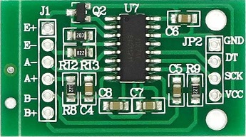
A small and very easy to use HX711 chip comes to our aid to amplify this signal. Its advantage is that it not only enhances, but also digitizes the evidence. Which we read with the help of the microcontroller of the printer.
I already purchased the microcircuit along with the necessary harness:
In order to measure the pressure created by touching the table with a hot end, you need to fix the extruder nozzle on the load cell or, in another version, make the scales from the table.
I chose the option of installing the sensor on the extruder.
In my implementation, it looks like this:

The hot-end radiator is mounted on one end of the sensor using a printed mount (red in the picture). The second end of the sensor is screwed to the extruder carriage. The attachment of the sensor to the extruder should not touch the carriage housing or the stepper motor.
The calibration procedure and the search for the zero point along the Z axis (homing) should be carried out on a heated extruder. Since the measurement of the sensor force occurs with a slight delay necessary for digitizing the voltage and transmitting it to the control controller, the measurement is performed 2 times with different sensor sensitivity:
Measurement of strong pressure (200-500 grams), while the table is pressed slightly but noticeably by the extruder. At this point, the “snot” of plastic is extruded, which may be contained on the extruder or on the table.
Lifting a short distance and repeated, accurate measurement (10-50 grams), there is a light, and very accurate touch by the extruder of the table.
In live it works like this:
To change the sensitivity of the sensor between attempts, you need to make small additions to the printer firmware. I made changes to the Marlin firmware, since it was installed with me and I have little experience in setting up and using it. I hope that someday my changes will be accepted into the main repository, but for now you can download it here: github.com/necdnk/Marlin.git (The config is configured for my Prusa Mendel i2)
I didn’t want to build a bicycle (library for using HX711), and a wonderful library was found on the github: github.com/bogde/HX711
But as it turned out later, I had to rewrite it a bit.
The connection diagram of the sensor to the arduino, simple to madness, you just need to connect 8 wiring to the scarf with the ADC.
4 to the load cell:
E + red
E- black
A- green
A + white
AND 4 to RAMPS (shield for arduins):
GND Earth
DT D4 pin arduines
SCK D5 pin arduins
VCC + 5v The pins
on the board are used to connect servos and are located nearby.
Settings in the firmware config that affect the sensor’s response force:
#define WEIGHT_SENSIVITY_HARD 25 // first attempt
#define WEIGHT_SENSIVITY_ACCURATE 2 // second attempt
If you want to specify the response force in grams and not in arbitrary units, like mine, then you need to select the value constants:
#define WEIGHT_SCALE 1000.f
You can purchase a sensor and an ADC chip with the necessary harness on all well-known trading floors.
The sensor is searched by the key words “load cell 5kg”.
The chip can be found by its name HX711.
Ready to listen to questions, additions and corrections.
To install this gap, there are several technical (and not so) solutions. For example:
- Placing a sheet of paper, and setting the starting point until the paper begins to move between the nozzle and the table with a slight effort.
- Using a micro switch that is pressed when the extruder approaches the table. Instead of a micro switch, an optical sensor is sometimes used, which also adds a little accuracy to the measurements.
- Capacitive proximity sensor.
But they all have flaws. The micro switch and the capacitive sensor are removed at a certain distance from the extruder nozzle, and also require height calibration relative to the level of the extruder. A sheet of paper, to put it mildly, is not technological, and with its help it is impossible to use the auto-poor functionality (measuring the curvature of the table).
On my Prusa Mendel i2, it was constantly necessary to set the height of the first layer after printing lasting more than an hour. And when the printer is idle, I had to adjust the height again. I suppose that during long-term operation of the printer, the structure warmed up and changed its size, thereby increasing the height of the first layer. Because after long work it was necessary to reduce the height, and after cooling, increase it.
Applying such a self-leveling device, I completely got rid of “dancing with a tambourine” near the printer when printing the first layer.
I suggest that the "rugged" owners of 3D printers repeat my decision.
I have developed and successfully tested on a Prusa Mendel i2 printer, a more accurate method for setting the distance between the extruder nozzle and the table. Which is based on measuring the pressure force of the extruder nozzle to the table using a strain gauge. Experienced users and CNC designers will say that this method has already been tested and the error of such a measurement will depend on the ambient temperature, but believe me (to my word, until you read to the end), this solution does not depend on temperature.
To repeat the design, not so much
is needed: - Strain gauge.
- Signal amplifier with ADC.
- 3D printer and some plastic to print some structural elements.
The first 2 points are "penny": in China, 200 rubles. (04.16.2015) or in Russia, naturally more expensive. And the presence or acquisition in the near future of the third paragraph is confirmed by the fact that you are still reading this text.
The time required to complete the printer is no more than one evening. Of course, not counting the time spent printing fasteners using a 3D printer.
And now for the details.
For the prototype, I used a load cell from Chinese household kitchen scales, but analogues of such sensors can be purchased in Russia.
What is a load cell and how does it work?
Strain gauge (strain gauge; from Latin tensus - stress) - a sensor that converts the strain to a convenient signal for measurement (usually electric):
The sensor I used is a small aluminum bar 12.8 x 12.8 x 65 mm, 4 strain gages are glued on its two faces (a resistor changes its resistance to the amount of tension). These resistors are connected to the Winston Bridge. The input of this bridge is supplied with voltage, usually 3-30 volts, and at the output we get a small change in voltage from the applied pressure (curvature of this bar) within 0.7 millivolts per 1 volt supplied to the input. But such small voltage changes cannot be measured immediately with the microcontrollers used in most 3D printers.
A small and very easy to use HX711 chip comes to our aid to amplify this signal. Its advantage is that it not only enhances, but also digitizes the evidence. Which we read with the help of the microcontroller of the printer.
I already purchased the microcircuit along with the necessary harness:
In order to measure the pressure created by touching the table with a hot end, you need to fix the extruder nozzle on the load cell or, in another version, make the scales from the table.
I chose the option of installing the sensor on the extruder.
In my implementation, it looks like this:
The hot-end radiator is mounted on one end of the sensor using a printed mount (red in the picture). The second end of the sensor is screwed to the extruder carriage. The attachment of the sensor to the extruder should not touch the carriage housing or the stepper motor.
The calibration procedure and the search for the zero point along the Z axis (homing) should be carried out on a heated extruder. Since the measurement of the sensor force occurs with a slight delay necessary for digitizing the voltage and transmitting it to the control controller, the measurement is performed 2 times with different sensor sensitivity:
Measurement of strong pressure (200-500 grams), while the table is pressed slightly but noticeably by the extruder. At this point, the “snot” of plastic is extruded, which may be contained on the extruder or on the table.
Lifting a short distance and repeated, accurate measurement (10-50 grams), there is a light, and very accurate touch by the extruder of the table.
In live it works like this:
To change the sensitivity of the sensor between attempts, you need to make small additions to the printer firmware. I made changes to the Marlin firmware, since it was installed with me and I have little experience in setting up and using it. I hope that someday my changes will be accepted into the main repository, but for now you can download it here: github.com/necdnk/Marlin.git (The config is configured for my Prusa Mendel i2)
I didn’t want to build a bicycle (library for using HX711), and a wonderful library was found on the github: github.com/bogde/HX711
But as it turned out later, I had to rewrite it a bit.
The connection diagram of the sensor to the arduino, simple to madness, you just need to connect 8 wiring to the scarf with the ADC.
4 to the load cell:
E + red
E- black
A- green
A + white
AND 4 to RAMPS (shield for arduins):
GND Earth
DT D4 pin arduines
SCK D5 pin arduins
VCC + 5v The pins
on the board are used to connect servos and are located nearby.
Settings in the firmware config that affect the sensor’s response force:
#define WEIGHT_SENSIVITY_HARD 25 // first attempt
#define WEIGHT_SENSIVITY_ACCURATE 2 // second attempt
If you want to specify the response force in grams and not in arbitrary units, like mine, then you need to select the value constants:
#define WEIGHT_SCALE 1000.f
You can purchase a sensor and an ADC chip with the necessary harness on all well-known trading floors.
The sensor is searched by the key words “load cell 5kg”.
The chip can be found by its name HX711.
Ready to listen to questions, additions and corrections.