Creating a WX-Mouse in the razer Mamba TE
The W-Mouse project has grown to using the high-end PMW3360 sensor. W-Mouse is a mouse developed by a person with the nickname Walkie, including circuitry and software.
Previously, avago sensors were used - adns-30x0, adns-60x0, adns-9x00 in conjunction with the atmega32u4 controller.
The new version uses the top-end 3360 sensor and atXmega128a4u controller and is called W X -Mouse.
Main advantages of W-Mouse
- The accuracy of the sensor is ensured, including by setting the sensor to the height of the best focus, this is possible because W-Mouse can display graphic images read directly from the sensor i.e. We see the surface of the mat with the “eyes” of the sensor.
- Optimum sensor operation on a specific surface.
- Setting the dynamics of movement. For example, you can configure the offset to be more “detailed” at low speeds, and with an increase in mouse speed, the offset is accelerated.
As a result, precise, detailed pixel targeting and quick turns, without the use of huge rugs and sweeping movements.
Or for example, you can configure the sight to be more responsive at the beginning of the movement, this is useful for tracking a moving "back and forth" target (tracking a target).
- The ability to use custom filtering - it is convenient to draw straight lines in CAD programs.
WX-Mouse can be assembled in almost any enclosure.
This is what the WX-Mouse setup window looks like.

All this makes W-Mouse a unique mouse.
The project is discussed at the Overclockers forum in the topic “Laser Optical Sensor”.
As an example, the mouse can be written as a pen.
(drawn in paint at a scale of 100%, the height of the letter was approximately 4-5 mm on the screen)

Action plan for remaking Mamba TE in the WX-Mouse:
1. Call the “circular” backlight scheme and determine what needs to be changed to use the RGB LEDs on both sides.
2. Combine with the “circular” backlight LEDs on the wheel and logo on the back.
3. Match the “white balance” and the brightness of the three parts of the backlight (so that the glow is the same)
4. Trim the main board of the mouse, leaving only the buttons and the USB connector.
5. Put the connector on the main board to connect the wxmouse board and make connections from the buttons and wheels to this connector.
6. Determination of the optimal height of the sensor.
7. Placement of the WX-Mouse board (controller + sensor) at the bottom using racks.
8. Upgrade the main cable.
9. Elimination of small jambs and final assembly.
Further photos with brief explanations, if there are questions on specific details, with pleasure, in more detail, I will answer in comments.
Item 1. Backlight
One of the most time-consuming and dreary moments, although when everything worked out, of course it was a pleasure.
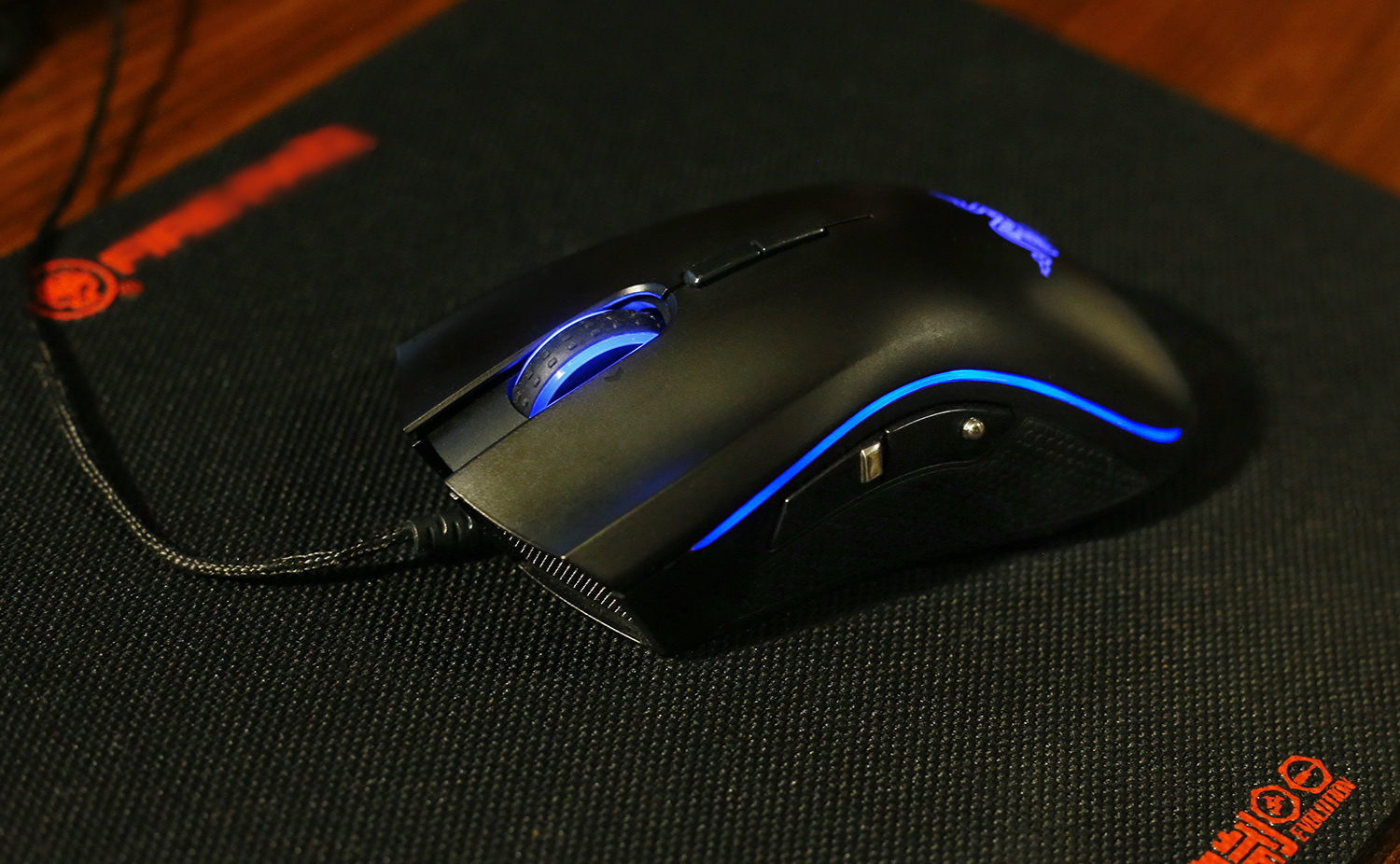
Mamba uses a thin luminous strip along the edges of the mouse body.
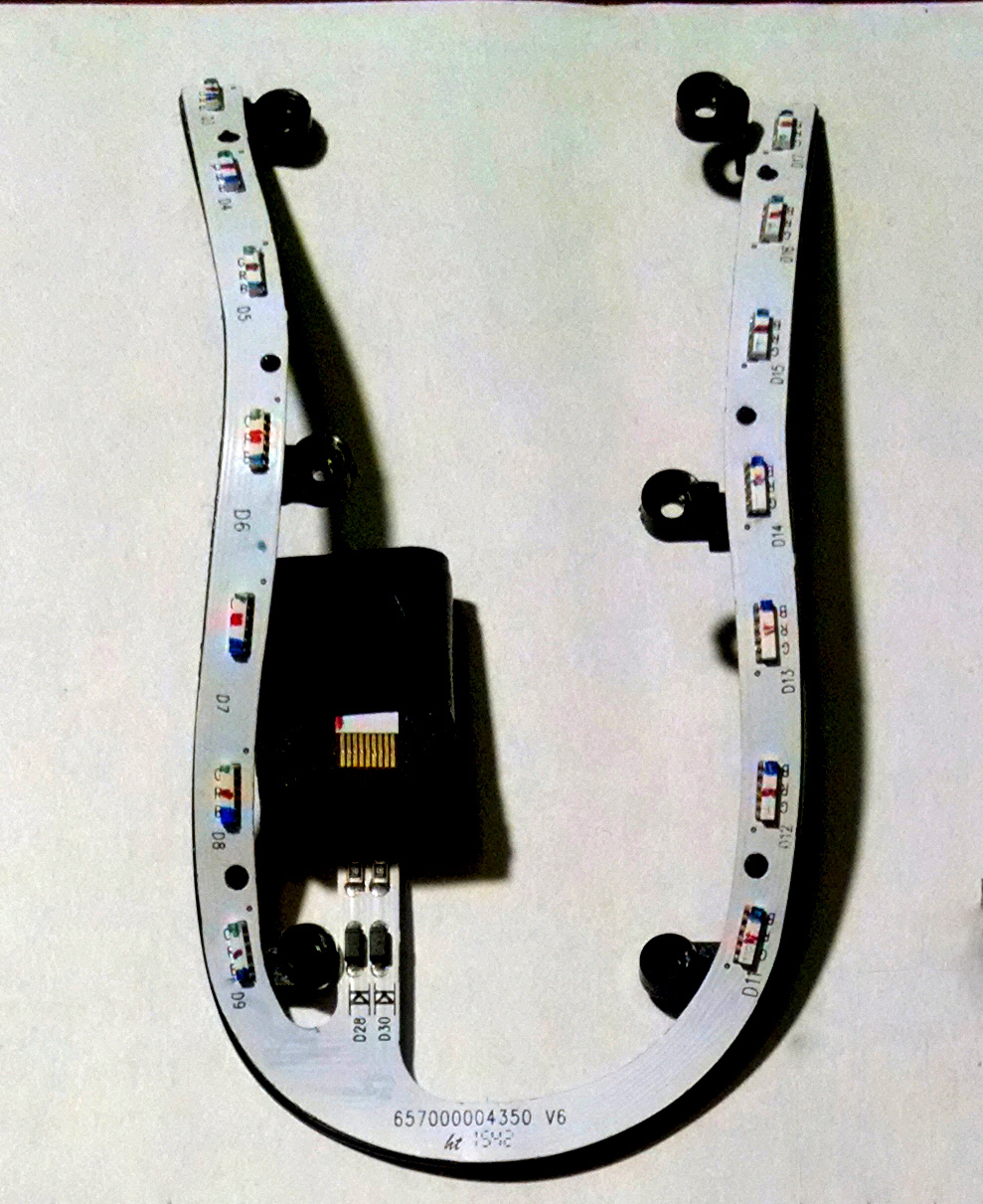
To do this, the designers put on each side 7 independent RGB LEDs.
Razer designers managed to make independent control, each of 42 LEDs, through an 8-pin connector.
Having made a call, he took off the circuit.
After analyzing the circuit, it was determined what changes should be made to connect the anodes and the rgb channels.
Backlight circuit
As you can see, the conclusions of each color are connected in parallel. But the management i.e. Anodes (purple color) Odyssey is scattered, including on color channels.
I needed to connect the LEDs of each color in parallel, as well as connect all the anodes and get 4 lines at the output - anodes plus three colors.
Yes, I know - connecting LEDs in parallel is not a good solution, but in this case there is no other option - because To place a resistor near each of the 42 LEDs is simply not realistic.
Given that to indicate the selected profile, mostly pure colors i.e. blue, red and green, then the unevenness and differences in the glow of individual LEDs will not be very noticeable. This point has already been tested on previous designs.
It took about 4-5 hours of picking with small LEDs and hidden paths to work on modifying the backlight, but it worked out.
Item 2. Combining the three parts of the backlight
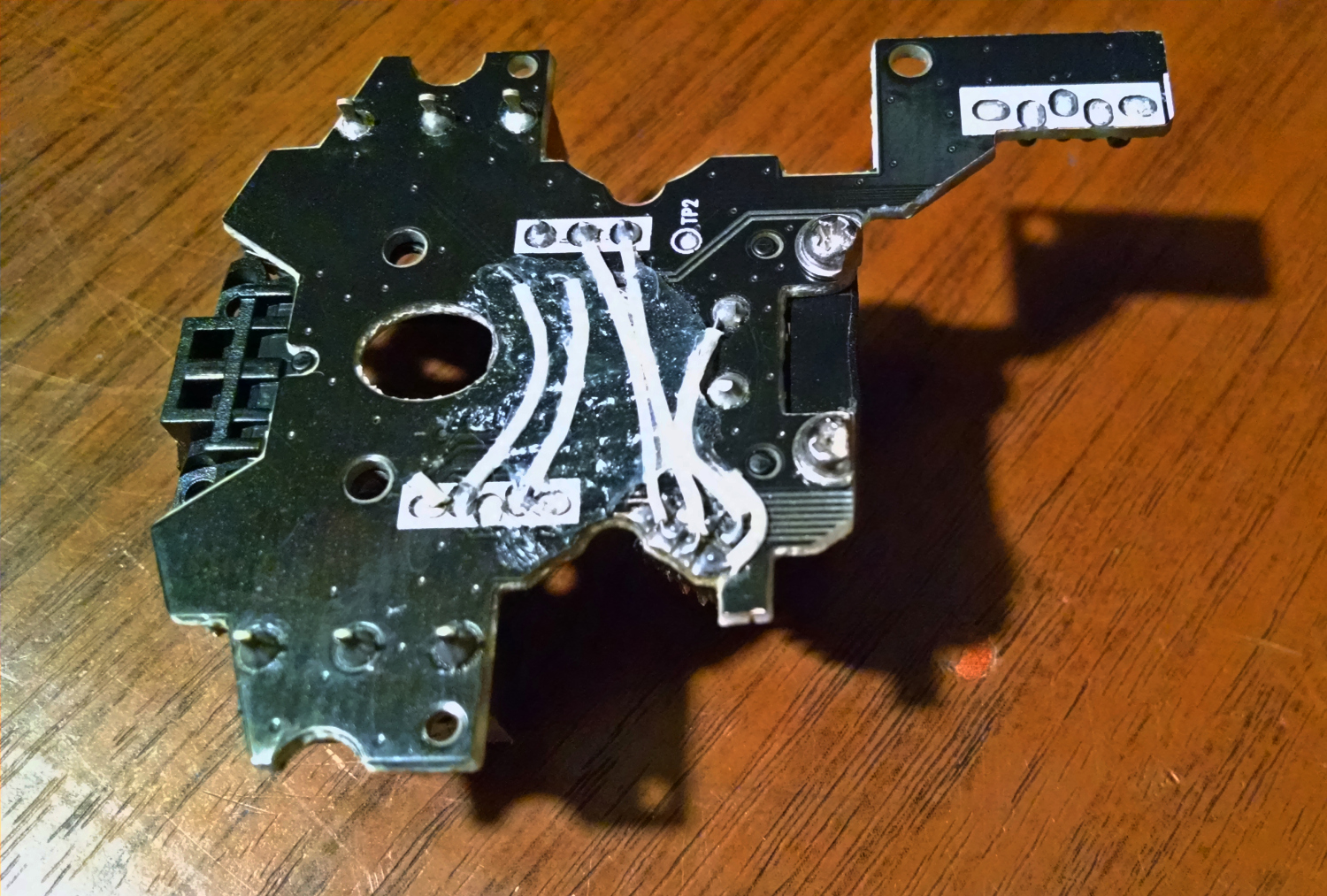
The final connection of the rgb channels from the two halves of the horseshoe is already done on the loop connector, there are also placed resistors for each color. The connector, with part of the board, was cut from the main board of the mamba. On this trim, an additional connector was placed to connect to the WX-Mouse board, as well as a platform for connecting to the backlight of the wheel and logo.

this is how this shawl is attached to the top cover of the mouse

Item 3. Harmonization of the glow of the three parts of the backlight
"White balance" is performed using variable resistors, one for each channel.
The resistor goes to the "ground", the anode is + 3.3V i.e. all three channels should glow as much as possible, ideally forming a white color.
Variable resistors allow you to adjust the brightness of each color so that the overall glow is as close to white as possible.
After measuring the values of the variable resistors, they are replaced by constant resistors.
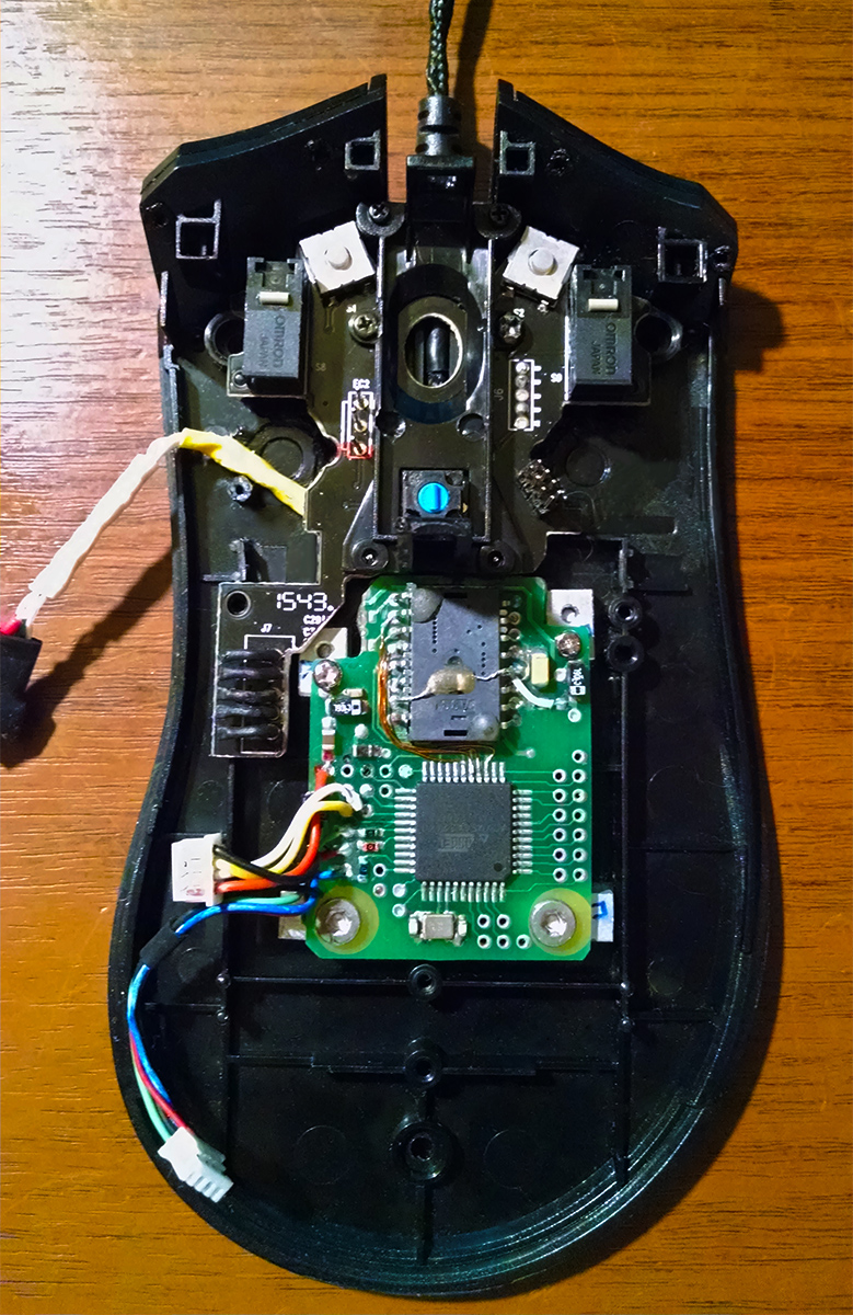
Item 4. Trimming the main board
In general, there’s nothing special here - a dremel, a diamond disk - a whack and there is a stub with buttons and a USB connector :)
At first I planned to use the USB connector of my motherboard to connect a USB cable, but since USB is not needed on the main board, but it’s used only on the WX-Mouse board, then this connector is redundant. Therefore, I made a USB cable lock out of the connector pins. As a result, the USB cable plugs into the connector, on a small ribbon cable coming from the WX-Mouse board.

Item 5. Connector for buttons and wheels
On the stub of the motherboard, a small 8-pin connector was placed for buttons and wheels.
Connections from buttons with a connector are made on the back of the board. In part, already existing board connections were used. The wiring is fixed with silicone sealant.
Point 6. Determination of the optimal height of the sensor
The PMW-3360 sensor is located on a small board, together with the atxmega128a4u controller. The


selection of height for the best focusing is facilitated by the WX-Mouse's ability to display video as the sensor sees the surface.
Example.
In the first half, the sensor is over ordinary writing paper, you can see how the focus changes when the height of the sensor changes. In the second part, a fabric rug, such as "control" ie with rough weaving.
Item 7. Placement of the board with the controller and sensor
The WX_Mouse board is located on aluminum racks. Racks were cut out of the plate - the thickness of the plate is the height of the racks. The final height adjustment is carried out by thin gaskets under the racks.


view from the bottom

Item 8. Cable Upgrade
The cable is being finalized by replacing the initial 40-50cm segment with a thin, flexible cable twisted from four MGTF wires. Two pairs are twisted separately - power and data, then they are twisted together, i.e. twisted pair cable is used. A cloth braid is worn on top, the same as on the native cable. The result is a very light and flexible cable, which is almost not felt. If you put two mice, one with this cable and the second wireless, then with your eyes closed, determine where which will not work (at least for me :)).

On the side buttons are visible small metal “pimpochki”. Without them, in tense moments, erroneous clicks occurred. "Pimpochki" made of stainless steel.
In addition to remaking mice in W-Mouse, I am engaged in their repair, if you contact me, I will consult or repair.