New features of LCD serial interfaces
When this idea arose, an LCD indicator with a serial bus was required. There was no modern display at hand and an ancient LCD with the µPD7225 driver was taken for verification. When the problem was solved, it became clear that the indicators available today are just a special case.
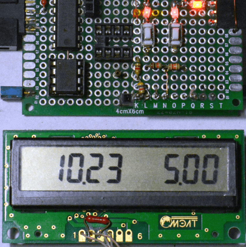
When using microcontrollers with a small number of legs, you often encounter the problem of a lack of input / output ports. The resources of the microcontroller are enough "for the eyes" to solve the task, but there are no ports. There is a temptation to "load" already occupied. As an example, consider a simple two-channel voltmeter on the tiny13 MK, in which two ports are analog inputs and two are the serial interface of the LCD. It is possible to expand the functionality of the device only using the serial data bus (SD). Moreover, she almost always rests. Data transfer to the indicator takes a maximum of two to three hundred microseconds, updating no more than once every 300 ms. The clock line (CLK) cannot be used for obvious reasons. A simple little device lacks a couple of buttons to switch modes and display these modes, especially when the display capacity is low. That’s the task ...
First, connect the indicator to a two-wire serial interface. To control the LCD with µPD7225, 6 signal lines are required: RESET, CS, C / D, BUSY, SI, SCK. The last two have nothing to discuss, we have already mentioned them. The rest, in order: reset, chip selection, command / data and availability, which is generated by the LCD driver. The two-wire display connection diagram is shown in Fig. 1 on the right. The chip is reset once when the power is turned on and is carried out by the R2C2 circuit provided for in the driver documentation.
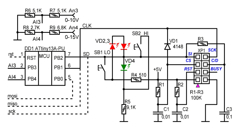
Active low CS is formed by a low level on the synchronization line. While data is being written to the LCD, capacitor C1 is discharged via diode VD1. After the last recording, CLK is set to "1" and C1, charging through R1, removes the resolution of the crystal.
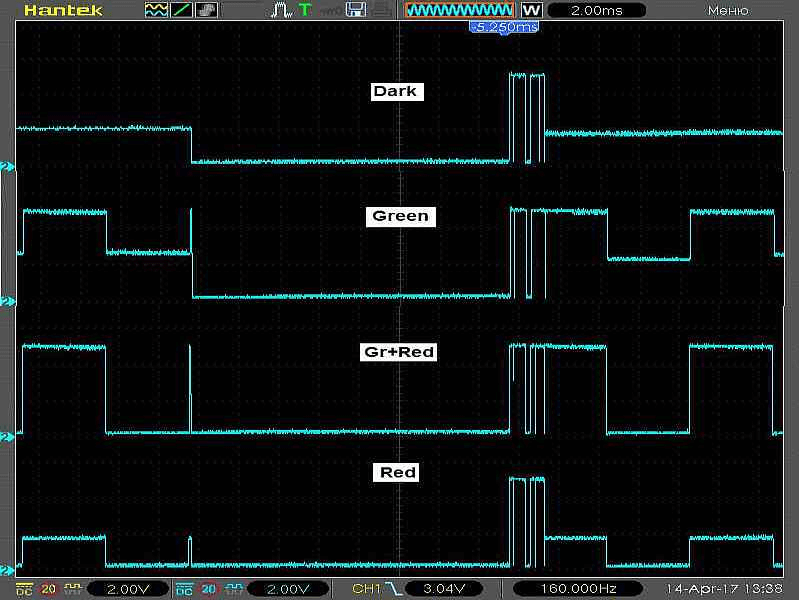
Before writing the command sequence to the indicator, on the SD bus you need to set a high level and wait for the C3 to charge through R3. Writing a few bytes is not enough for the voltage on C3 to change significantly. To write data, the C3 is low on SD. Instead of polling the BUSY signal, which is expensive to do, the program generates a time delay after the edge of the pulse, before writing another byte. The ready signal is removed by the driver after each byte is written and when CS is removed, as shown in the waveform.

To be sure of the reliability of the circuit, we tested another LCD with a similar interface - KTM-S1201. The driver is the same, clock parameters differ by 20%.


I had to adjust the delay constants and add the missing contrast adjustment circuit. The pt13.asm program is intended for the 8-bit NEC indicator, and the pt23.asm for the 12-bit KTM-S1201. Connection to the microcontroller through the standard 8-pin rectangular connector for these indicators.

It is clear that more modern LCDs with sequential control are much easier to connect to two buses.
The control and indication circuit is shown in Fig. 1 in the center. A chain of three LEDs and a pair of resistors with two conventional buttons without fixing allows you to get the set of voltages in the nodes that is necessary and sufficient for reliable identification of pressing, and also allows, using the capabilities of the standard output of the port, independently control two LEDs of different colors. We will consider series-connected red diodes as one with a double direct voltage drop. Since LEDs are used here not only for their intended purpose, but also as zener diodes, for a start we will warn that any replacements with LEDs with a color other than those indicated are unlikely to lead to good results. The same applies to the supply voltage of the circuit.
In the initial state (buttons are not pressed), the voltage at the junction point of 2.1V diodes. There is no glow, there is little voltage on each of the diodes. Pressed upper / lower - 1.4 / 4.8V. To distinguish between the levels, the microcontroller must be able to analog-to-digital conversion on the selected port for connecting the circuit. Further, everything is standard.
The port can be configured as an input, converting the input voltage, comparing the code with the set thresholds, suppressing "bounce" and generating flag flags. The logic of the scanning program is arranged so that the first press of the selected button sets its flag, the second - resets. Another program controls the LEDs. The third state of the port is used to independently turn them on and off. A low level of the port illuminates the red LEDs, a high - green. So that all the LEDs can glow at the same time, the usual principle of dynamic indication is used. The costs of maintenance are minuscule.
The control circuit for its single input / output is connected to the SD bus of the serial LCD interface. In the pause between calls to the indicator, the bus is switched to high impedance, and the clock bus is in the passive state. Now the level on the SD bus is determined by the LED-resistive-button circuit, which can vary in one direction or another from the average, depending on the button pressed, by the magnitude of the direct voltage drop across the LEDs. After the ADC cycle, the microcontroller, in the time-sharing mode, controls the LEDs. The circuit can optionally be connected to any convenient port of any microcontroller for operations of setting up, checking, or searching for program glitches. In this case, it is necessary to provide for a simple check of its presence during initial initialization, the sign of which is the voltage level "
The operation of the control circuit is illustrated by the waveform of the signals on the SD bus of the serial interface. The little checkmark on the left is the moment the buttons were polled. "Palisade" to the right of the center - indicator update.
When choosing an element base, consider the following. Green SMD LEDs are rejected due to low brightness at the selected current. I had to use a 3 mm LED. To test, connect it to the 5V circuit through a 10K resistor. Brightness should suit you. Red LEDs are suitable for any. You do not need to pay attention to the LED glow at the moment you press the button (this is the scheme), because The information in the microcontroller register changes when the button is released. Still some time is required to activate a new output cycle (the old one may not be finished yet), so take this as a wink of the controller to you personally, no more. No inconvenience was noted during work. The only feature, a short flash of LEDs when the indicator is updated, can be considered an indication of the operating status of the device.
The demo program is written in assembler, compiled for ATtiny13 under two indicators and contains only what is necessary for understanding the principle of joint operation of the interface and the control circuit in a real device. The LED of the corresponding button lights up at the first press and goes out at the second. This limits the processing of click flags in the program. The developer has at his disposal a free port for control depending on the functional purpose of the device and the "reset" input is in reserve. The remaining free program memory, and this is almost half of all, should be enough to give the device specific additional functions. Using tiny25 / 45/85 generally removes the memory problem.
To select the conversion factors of the channels of the voltmeter, the Coef constants in the source are used. Their selection during compilation of the program makes it unnecessary to use trimming resistors in the input circuit dividers and allows the use of a voltmeter in the input voltage range up to 99.9V. Although two digits are displayed after the decimal point, it should be understood that accuracy is limited by the resolution of the ADC of the microcontroller. Averaging over 64 samples allows you to observe changes within tens of millivolts of input voltage above 10V with high stability of readings. The values of the resistors of the input dividers are selected from the condition of not exceeding the supply voltage of the microcontroller with the subsequent correction of the constants in the program to match the readings. The values of fuses MK in the source text. You must turn off the divider by 8, the rest is the default.
The author draws attention to the fact that the choice of a voltmeter to demonstrate the additional capabilities of the serial interface is purely pragmatic. It was easy to add a couple of functions to the test program. The application of this idea in designs on microcontrollers in cases with a small number of ports allows you to expand the functionality already in finished devices by simply connecting the described control circuit and modifying the software component.
Part 2. "But whether to swing ..."
The I2C bus also applies to two-wire interfaces. It would be tempting to transfer the idea of using the serial bus twice and onto it, especially since there are many LCD indicators of this standard. Even a domestic manufacturer produces a dozen items.
The obvious solution is to flip the sequential LED resistive circuit so that at the midpoint in the initial state there is a voltage above half the supply voltage, it does not pass. The operation of the bus is based on the principle of "mounting or" and the low-level current must be within the required limits. To ensure this parameter, while maintaining the ability to identify button presses at different voltage levels at the connection point of the indicator LEDs, allows the circuit shown in Fig. 2.

To offset the initial level, a parametric stabilizer is used on the VD3 LED, through which the resistor R3 sets the current. This LED can be used as an indicator of the operation of the device. The demonstration program of the voltmeter described above, but intended to work with the MT-10T11 indicator (MELT LLC) and the control-indication circuit, is present.

ATTENTION: the pull-up resistor of the SDA bus is not installed, its functions are performed by
the control-indication circuit. The SCL bus pull-up resistor is mounted on the indicator.