LED cube 8x8x8, interesting and beautiful
Introduction
This idea came to my mind spontaneously, until the fall of this year I could not even guess that people were doing something similar in life. In fact, about the fact that such "cubes" exist, said the teacher of circuitry and suggested taking this topic as a coursework.
Looking ahead, I want to say that you do not need to think about the volume of work as something colossal. On the contrary, I had to do quite a bit, but those who think: “Ha, I will do it in a couple of days,” - get ready for the opposite. Yes, and the process itself involves in writing work no worse than writing some kind of program code ...
Watching small works of size 3x3x3, 4x4x4, and 5x5x5, I slowly realized that the more the better.
Milestone # 1:
If you have not worked with a soldering iron before, realize first that you need to solder all the legs of the LEDs, this is 2 * 512, not so little. So practice on some cats.
The Internet is full of instructions on this subject. But from start to finish, I saw it seems only on instructables.com, and I’ll say right away, somehow it’s too detailed in terms of everything. I personally used two times less components. Naturally, the equipment was simpler. As a result, for our little toy we will need:
- 512 LEDs ($ 6 - aliexp)
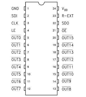
- 5 special microcircuits for STP16CPS05MTR LEDs ($ 9 - aliexp) it is
more profitable to take such parts in batches naturally
- 8 BD136 pnp transistors (domestic analogs will also work)
- 5 1kOhm of resistors (working power 2 W)
- 5 10mkF capacitors (operating voltage 35-50 V)
- connecting wires (about 10 m came out, given the failure), solder and everyone who is high
Time to start making the layout
We take a drill, a ruler, make an 8x8 grid (the main thing is not to do 8x9, like me) on anything, whether it’s polystyrene, a wooden board or something else. And carefully drill holes for the LEDs.
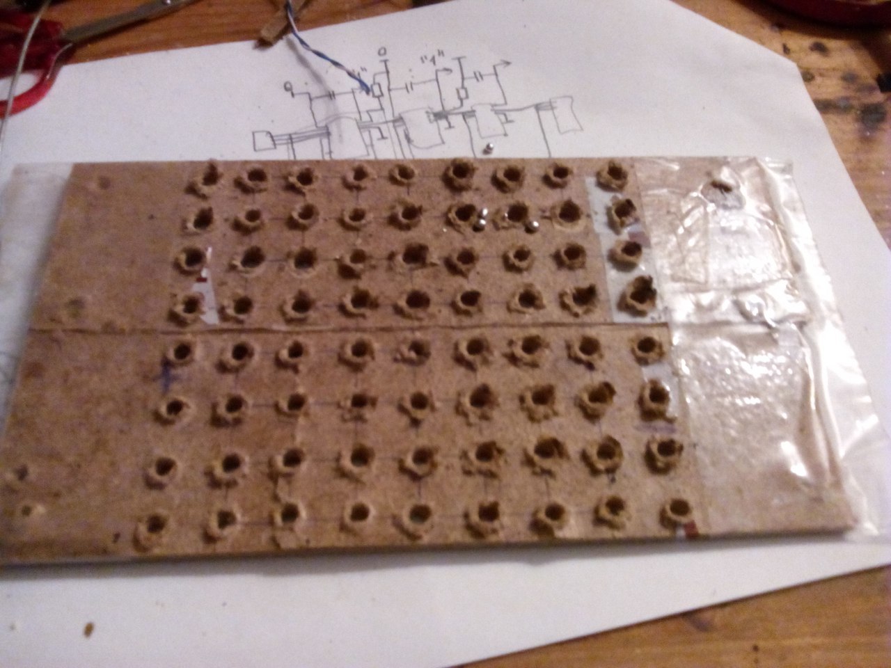
Milestone # 2:
The key word is “neat”, a couple of millimeters left or right, and you will already have a curved cube in the end.
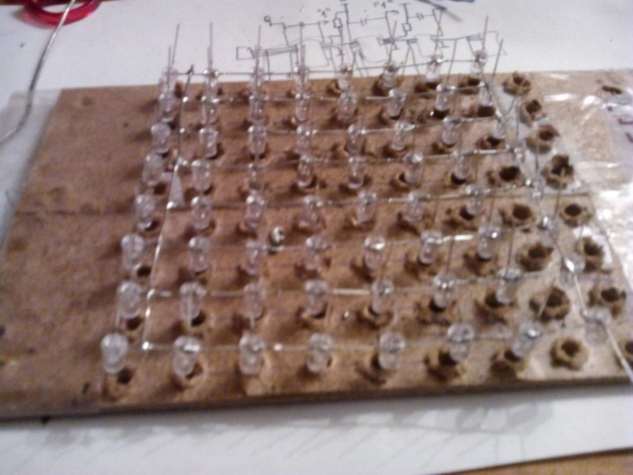
After this step is completed, we insert the LEDs into the cells and observe the following rule:
a) All anodes should be on the left and the cathodes on the right. Or vice versa. As you prefer.
b) The very first row from above must contain LEDs at an angle:

By this principle, we connect the cathodes (-). Where it is marked with a dotted line, attach some kind of wire so that the layer holds firmly on both sides.
Holding this tender layer, it may seem to you that it might fall apart, but in fact, when you begin to fasten the layers, then this structure can be safely thrown to the floor, and most likely nothing will fall apart.
First layer total
Before you begin to solder the second layer, you need to take and bend all the anodes as follows:

Merge Multiple Layers

Milestone # 3:
Beginners, please use a special solder paste (flux) if you are dealing with wires, so save yourself a lot of nerves (not like the first time).
When you are a little tired
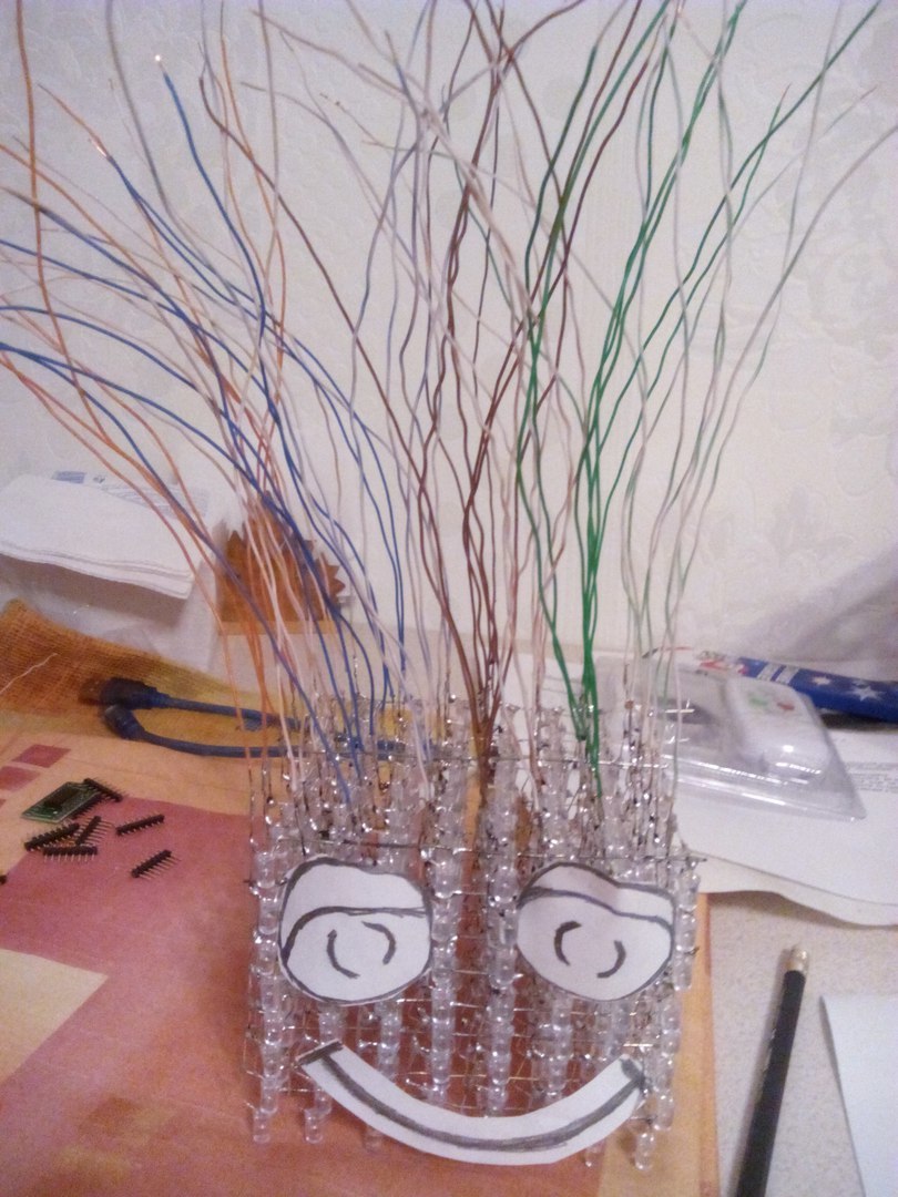
So, soldering 64 wires to the anodes, which we got "at the bottom", you can proceed to the electronic circuit itself.
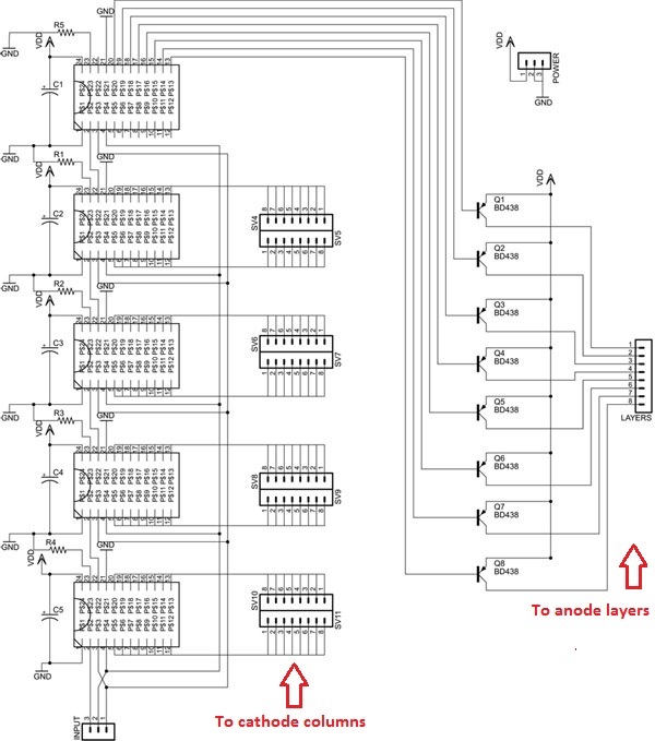
We see that the outputs of our microcircuits on both sides go into the common anodes of the cube columns, and in the 5th we multiplex layer control through transistors. It seems that everything is not complicated: a signal is sent to certain columns and layers, and we get a pair of luminous LEDs.
In fact, it works like this:

There are 3 inputs: clock, data and latch. When 8 bits have worked out, the latch goes and the data is put into the register. Because our microcircuits are made on shift registers, in order to render our cube 1 time with different bits of information, we need to write 1 byte (8 bits with the numbers of layers to which voltage is applied), then there will be empty data, because for the fifth chip, we have left pins connected to nothing. Next, we write 1 byte for each of the group of eight columns. The corresponding bit will determine which column should be lit, and where it intersects with the activated layer, the LED at their intersection should receive voltage.
Below is a diagram from the developer datasheet for general reference:
How will we write 1 byte of data:
void CUBE::send_data(char byte_to_send){
    for(int i = 0; i < 8; i++){
        if(byte_to_send & 0x01<<i){
            digitalWrite(SDI, HIGH); // согласно тайминговой диаграмме сначала активное состояние на линии данных
        }
        digitalWrite(CLK, HIGH); // затем на линии тактирования
        digitalWrite(SDI, LOW);
        digitalWrite(CLK, LOW);
    }
}
void CUBE::latch(void){
    digitalWrite(LE,HIGH); // и точно также мы сделаем с операцией защелкивания.
    digitalWrite(LE,LOW);
}
I used Arduino UNO (I took it), but here any model will do. Both nano and mini, since only 3 digital inputs and vcc + gnd are used.
Separately, take care of the additional power supply unit (I used the adapter 12V 2A), to display all the layers it seems that the current is of such strength and is needed.
All source code in sketch form for Arduino will be here .
- You can do this thing yourself in a week, the main thing is to buy all the components;
- You can put extra. a real-time clock module, and this cube will work without connecting to a PC;
- You can, of course, customize this item with various buttons and radio controls, but I did not;
- Having trained on such a simpler option, I plan to soon assemble an RGB cube.
Many thanks are expressed to the author of this idea and spiritual leader Nick `Shulze. Materials taken from hownottoengineer.com. Good luck and success in all your creative endeavors!