Distributed control system based on SoC FPGA
Implementing a combination of FPGA firmware, NIOS microcontroller software, and Linux control software based on Altera Cyclone V SoC using Avalon Mailbox to create a distributed control system based on them.
In a distributed control system, one has to solve many different problems at different levels.
It is advisable to solve some problems at the level of an embedded PC with a full OS. A full-fledged OS is good because it has already implemented and debugged many useful tools, such as multithreading, ready-made drivers, libraries, various frameworks and more. And all this can be developed in high-level languages, without particularly going into the details of implementation at the lower level.
There are tasks that can be conveniently solved at the level of the microcontroller (hereinafter - MK), either without an OS (bare-metal) or with minimalistic real-time OS. Here, the key role is played by the ability to debug software inside the OS using JTAG and to monitor what is happening at the periphery of the MC at any break-point.
And there are tasks that should be solved already at the FPGA level, since no microcontroller may be enough for competent parallel control of various high-frequency electronics, for example, step drive drivers with data processing of encoders and speed controllers. In such tasks, the processor is simply superfluous.
The number of actuators and their various functions in the control system is greatly increasing when it comes to developing a device, for example, with a three-stage manipulator, a couple of servo motors, a dozen discrete devices, a bunch of peripherals on all popular interfaces (SPI, I2C, UART and etc.) and complex logic with mathematical analysis inside. And it is very convenient to place the entire control system in general on one chip, which will actually be done. As a result, all three levels of control PK-MK-FPGA and their interactions will move inside the crystal.
In this case, the inevitable task of creating a transport layer that connects all this complex logic with each other arises. For a bundle of MK-FPGAs, this is solved, in fact, by creating another peripheral device on a common MK bus with its own set of registers. But the task of creating a transport layer PK-MK will be solved a little differently.
For experiments, we need a real or virtual machine with Ubuntu 16.04 on board.
The source code for all programs is available on GitHub .
Imagine that all executive devices of the PC-MK-FPGA control system are reduced to parallel I / O ports. For example, as sensors and actuators, we restrict ourselves to a set of buttons and LEDs, and we will control them from the command line of the terminal.
All FPGA elements, including MK, will be synthesized. Part of the PC is already integrated into the chip and is based on the Cortex A9, whose buses are output to the FPGA and can be used directly. Therefore, all that will have to be done is to connect the modules necessary for communication with the synthesized nodes in the FPGA via standard means to the OS core.
As a hardware platform, we use the DE0-Nano-SoC kit .
We take as a basis the basic project my_first_hps-fpga_base from the DE0-Nano-SoC CD-ROM set (rev.B0 / rev.C0 Board) . The project contains a pre-configured environment with correctly set FPGA ports, a ready-made Cyclone V Hard Processor System unit with configured memory parameters and a set of auxiliary elements in Qsys. To work with the project, we need Quartus Prime 15.1 with the Cyclone V support package and SoC Embedded Design Suite .
We will make some changes to the project. Add the NIOS core, memory for it (16 Kb 32-bit wide) and JTAG port. We indicate in the NIOS parameters the addresses of the vectors from the added memory.
Avalon Mailbox is simplex, so we need two modules (like the RX and TX lines of a regular UART). The interrupt signal of each of the modules must be connected to the processor for which the module is receiving.
Add one port (8 bits) of input and output for further system testing.
After adding all the elements, you can automatically select addresses and interrupts.
Let's create ports for buttons and LEDs in the code of the upper module.
Connect the ports to soc_system.
We will assemble the project and get the FPGA firmware, on the basis of which we will continue to work.
In the NIOS II EDS environment, which is essentially Eclipse with all the necessary plug-ins, create a new soc_nios project from the “NIOS II Application and BSP” template. The result is two projects: directly firmware and BSP.
First of all, you need to immediately assemble the BSP, but not in the traditional way. Instead, in the context menu of the soc_nios_bsp project, you need to select the BSP Editor item in the NIOS II menu and enable the enable_small_c_library and enable_reduced_device_drivers options so that the firmware does not grow too much. Then assemble by clicking Generate . In the future, since the assembly parameters are preserved, you can rebuild the BSP simply by choosing from the NIOS II menuparagraph Generate BSP .
In the system.h file from the BSP project, you can see all the parameters of the peripherals of the MC that were previously added to the Qsys schema.
Read more about NIOS and how to build projects for it here .
It remains to assemble the project. The size of the NIOS firmware should be less than 16 Kb.
To test firmware on hardware, you need to create a new debugger configuration. After flashing the FPGA from Quartus Programmer, in the Debug Configurations menu, select the NIOS II Hardware option , update all interfaces and in the Target Connections tab we find jtaguart_1 . This is the same JTAG for NIOS that we previously added to Qsys.
Now you can start debugging from Eclipse. If everything is done correctly, the message “Turn the switch ON to activate the timer” should appear in the NIOS II console.
The whole process is described in detail here in sections 1 to 10. It is recommended to use more recent, fresh versions of the toolchain , bootloader, and kernel than those that can be found here. Please note that for building this version of the bootloader, a toolchain with a compiler higher than version 6 will not work.
Instead of the proposed sopc2dts utility, it is better to use the sopc2dts.jar script to generate a device tree, and you can specify --type dtb right away .
Using the latest Buildroot is highly recommended to get the system .. To build, you must force the environment variables CC as the path to arm-linux-gnueabihf-gcc and CXX as the path to arm-linux-gnueabihf-g ++ from the toolchain. Next, enter the used versions of the compiler, the kernel and the library (they will be prompted by the system itself during the build process). In the toolchain settings, when configuring Buildroot, you must specify the path to the toolchain, as well as the prefix $ (ARCH) -linux-gnueabihf and enable support for SSP, RPC and C ++.
For convenience, you can add nano, mc, and openssh packages to Buildroot.
Next, we will collect all the top-level software in Eclipse with the GNU MCU Eclipse plug-in . Create a new workspace for ARM projects and in the global Eclipse settings in the Workspace Tools Path section indicate the appropriate path to the installed version of Linaro.
First of all, let's make a driver for Mailboxes. Create a new nios_mailbox project in Eclipse from the “Hello World ARM C Project” template.
In the project settings, turn off the “Use default build command” and “Generate Makefiles automatically” options, because to build the kernel module, you need the make command TARGET = nios_mailbox TARGET_DIR = Default . Add to the environment variables two new entries CROSS_COMPILE and KDIR, indicating the full path with the toolchain prefix and the path to the kernel sources, respectively. Add __GNUC__, __KERNEL__ and MODULE to the list of defines. All. Now you can write code.
The kernel module will respond to an interrupt from iron and must somehow report this to the application world. For this purpose, we need to create our own signal.
We will create a driver based on platform_device, each Mailbox will be like a miscdevice, and ultimately it will be visible on the system as a device file in the / dev directory. More information about drivers and in general can be found here . It is important to understand that we can theoretically have any Mailboxes, and there is only one driver for all, and it must initialize and number them all.
If you don’t particularly go into details, then driver development comes down to the implementation of standard read and write operations to a file, plus a small bonus in the form of a special function ioctl (), which is needed to forward the driver id of the process that uses it. This is necessary in order to know which process in the system to signal the occurrence of a hardware interrupt. The interrupt handler itself looks pretty simple and very similar to its counterpart in NIOS.
It remains to assemble the project. To do this, we need to write a special Makefile. It will look like this.
And we also need to create a Kbuild file with one line.
We assemble the project in the traditional way. As a result, we get the kernel module nios_mailbox.ko , which we copy to the system and install using insmod. If everything is done correctly, in the Linux console opened via USB, when you click the appropriate button on the board, a message from the kernel "[.........] NIOS Mailbox new mail!" Should appear.
Of course, it would be necessary to add a buffer to the driver for received data on interruption, since reading by the application program may not keep up with the data stream from the iron. And the driver itself is better to assemble with the stripped option , to save space in the embedded system. However, these questions will be left to the reader for independent study.
So we got to writing a console application. Create a new soc_test project in Eclipse from the “Hello World ARM C ++ Project” template. Under Settings in the Target Processor choose cortex-a9 architecture in Cross ARM GNU G ++ Linker add -pthread . In the Build Artifact tab, you can remove the file extension. All other settings can be left by default.
It remains to assemble the project. As a result, we get an executable file for the ARM-9 architecture, which we copy to the system. If everything is done correctly, then after starting the message “Enter command (" read "(" r ")," write "(" w ")," reverse ")," q "to exit" will appear in the console.
Add the kernel module installation to Linux startup.
We will build a new version of the NIOS firmware by removing all debugging output from the program in JTAG. We convert the firmware to hex format by running the command "elf2hex --input = soc_nios.elf --output = soc_nios.hex --width = 32 --base = 0x4000 --end = 0x7fff --record = 4" in SoC EDS 15.1 Command Shell . The resulting firmware must be added as an initialization file for NIOS memory in Qsys, then rebuild Qsys, rebuild the FPGA project and write the new firmware to the memory card.
We boot and immediately launch the test application. And if everything was done correctly, then we get a working system.
Do not be afraid to use such complex bundles as FPGA-MK-PC based on SoC in your projects. This article has demonstrated that implementing such a system is not so difficult. You can even add several microcontrollers and tie them together in a similar way.
The control system, created on the basis of the above principles, was introduced by the author into one of the electronic devices and proved its operability in the real world.
Introduction
In a distributed control system, one has to solve many different problems at different levels.
It is advisable to solve some problems at the level of an embedded PC with a full OS. A full-fledged OS is good because it has already implemented and debugged many useful tools, such as multithreading, ready-made drivers, libraries, various frameworks and more. And all this can be developed in high-level languages, without particularly going into the details of implementation at the lower level.
There are tasks that can be conveniently solved at the level of the microcontroller (hereinafter - MK), either without an OS (bare-metal) or with minimalistic real-time OS. Here, the key role is played by the ability to debug software inside the OS using JTAG and to monitor what is happening at the periphery of the MC at any break-point.
And there are tasks that should be solved already at the FPGA level, since no microcontroller may be enough for competent parallel control of various high-frequency electronics, for example, step drive drivers with data processing of encoders and speed controllers. In such tasks, the processor is simply superfluous.
The number of actuators and their various functions in the control system is greatly increasing when it comes to developing a device, for example, with a three-stage manipulator, a couple of servo motors, a dozen discrete devices, a bunch of peripherals on all popular interfaces (SPI, I2C, UART and etc.) and complex logic with mathematical analysis inside. And it is very convenient to place the entire control system in general on one chip, which will actually be done. As a result, all three levels of control PK-MK-FPGA and their interactions will move inside the crystal.
In this case, the inevitable task of creating a transport layer that connects all this complex logic with each other arises. For a bundle of MK-FPGAs, this is solved, in fact, by creating another peripheral device on a common MK bus with its own set of registers. But the task of creating a transport layer PK-MK will be solved a little differently.
For experiments, we need a real or virtual machine with Ubuntu 16.04 on board.
The source code for all programs is available on GitHub .
Control system architecture
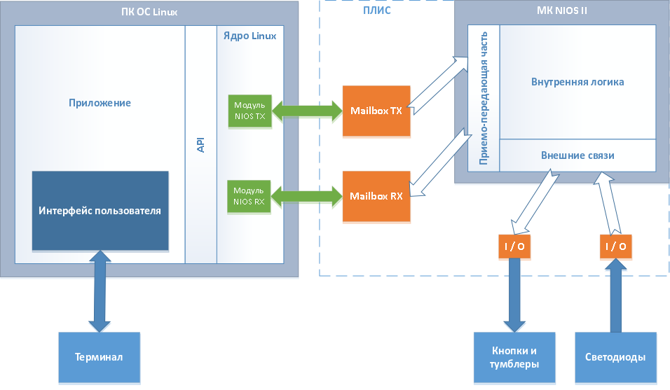
Imagine that all executive devices of the PC-MK-FPGA control system are reduced to parallel I / O ports. For example, as sensors and actuators, we restrict ourselves to a set of buttons and LEDs, and we will control them from the command line of the terminal.
All FPGA elements, including MK, will be synthesized. Part of the PC is already integrated into the chip and is based on the Cortex A9, whose buses are output to the FPGA and can be used directly. Therefore, all that will have to be done is to connect the modules necessary for communication with the synthesized nodes in the FPGA via standard means to the OS core.
As a hardware platform, we use the DE0-Nano-SoC kit .
Getting FPGA firmware
We take as a basis the basic project my_first_hps-fpga_base from the DE0-Nano-SoC CD-ROM set (rev.B0 / rev.C0 Board) . The project contains a pre-configured environment with correctly set FPGA ports, a ready-made Cyclone V Hard Processor System unit with configured memory parameters and a set of auxiliary elements in Qsys. To work with the project, we need Quartus Prime 15.1 with the Cyclone V support package and SoC Embedded Design Suite .
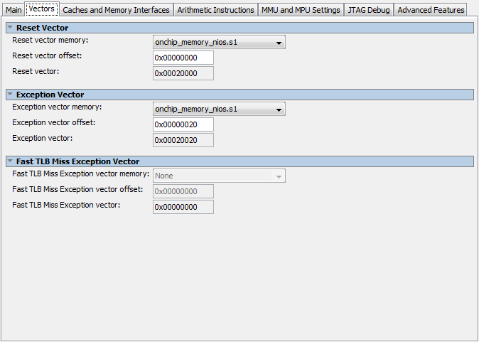
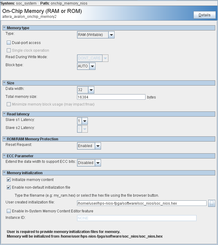
We will make some changes to the project. Add the NIOS core, memory for it (16 Kb 32-bit wide) and JTAG port. We indicate in the NIOS parameters the addresses of the vectors from the added memory.
Avalon Mailbox is simplex, so we need two modules (like the RX and TX lines of a regular UART). The interrupt signal of each of the modules must be connected to the processor for which the module is receiving.
Add one port (8 bits) of input and output for further system testing.
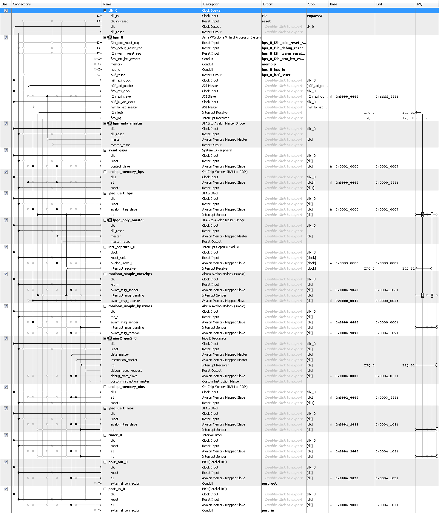
After adding all the elements, you can automatically select addresses and interrupts.
Let's create ports for buttons and LEDs in the code of the upper module.
  // Ports
  wire [7:0] port_out;
  assign LED = port_out;
  wire [7:0] port_in;
  assign port_in = {{2{1'b0}}, SW, KEY};
Connect the ports to soc_system.
  // FPGA Partion
  .port_out_export(port_out),  // port_out.export
  .port_in_export(port_in),    // port_in.export
We will assemble the project and get the FPGA firmware, on the basis of which we will continue to work.
Algorithm
So, create a system that will do the following:
- When you turn on the toggle switch, a timer is activated;
- According to the timer with a frequency of 1 Hz, one of the LEDs will light up in order;
- At the touch of a button, the direction will change;
- When a READ command is received from the PC, the number of the current active LED will be sent to the standard Linux console;
- When receiving a WRITE command from a PC, the current active diode will change;
- When you receive the REVERSE command from the PC, the direction will change, the same as from the button;
- By pressing another button, the number of LED switches from the moment of the last reverse will be sent to the PC console.
On the side of MK
In the NIOS II EDS environment, which is essentially Eclipse with all the necessary plug-ins, create a new soc_nios project from the “NIOS II Application and BSP” template. The result is two projects: directly firmware and BSP.
First of all, you need to immediately assemble the BSP, but not in the traditional way. Instead, in the context menu of the soc_nios_bsp project, you need to select the BSP Editor item in the NIOS II menu and enable the enable_small_c_library and enable_reduced_device_drivers options so that the firmware does not grow too much. Then assemble by clicking Generate . In the future, since the assembly parameters are preserved, you can rebuild the BSP simply by choosing from the NIOS II menuparagraph Generate BSP .
In the system.h file from the BSP project, you can see all the parameters of the peripherals of the MC that were previously added to the Qsys schema.
Read more about NIOS and how to build projects for it here .
To solve the problem at the MK level, we need:
- Timer interrupt handler;
void TIMER_0_ISR(void* context) { IOWR_ALTERA_AVALON_TIMER_STATUS(TIMER_0_BASE, 0); IOWR_ALTERA_AVALON_TIMER_CONTROL(TIMER_0_BASE, ALTERA_AVALON_TIMER_CONTROL_CONT_MSK); led += step; if(led > LED_MAX) { led = 0; } if(led < 0) { led = LED_MAX; } IOWR_ALTERA_AVALON_PIO_DATA(PORT_OUT_0_BASE, (1 << led)); count++; IOWR_ALTERA_AVALON_TIMER_CONTROL(TIMER_0_BASE, ALTERA_AVALON_TIMER_CONTROL_CONT_MSK | ALTERA_AVALON_TIMER_CONTROL_ITO_MSK); } - Mailbox interrupt handler;
void MAILBOX_HPS2NIOS_ISR(void* context) { IOWR_ALTERA_AVALON_MAILBOX_INTR(MAILBOX_SIMPLE_HPS2NIOS_BASE, 0); //NOTE: Order is important! CMD register should be read after PTR register buffer[1] = IORD_ALTERA_AVALON_MAILBOX_PTR(MAILBOX_SIMPLE_HPS2NIOS_BASE); buffer[0] = IORD_ALTERA_AVALON_MAILBOX_CMD(MAILBOX_SIMPLE_HPS2NIOS_BASE); alt_printf("Reading: 0x%x 0x%x\n\r", buffer[0], buffer[1]); newMail = true; IOWR_ALTERA_AVALON_MAILBOX_INTR(MAILBOX_SIMPLE_HPS2NIOS_BASE, ALTERA_AVALON_MAILBOX_SIMPLE_INTR_PEN_MSK); } - Message parser and write function in Mailbox;
- Button polling and LED control functions.
It remains to assemble the project. The size of the NIOS firmware should be less than 16 Kb.
To test firmware on hardware, you need to create a new debugger configuration. After flashing the FPGA from Quartus Programmer, in the Debug Configurations menu, select the NIOS II Hardware option , update all interfaces and in the Target Connections tab we find jtaguart_1 . This is the same JTAG for NIOS that we previously added to Qsys.
Now you can start debugging from Eclipse. If everything is done correctly, the message “Turn the switch ON to activate the timer” should appear in the NIOS II console.
PC side
Install Linux on a board
The whole process is described in detail here in sections 1 to 10. It is recommended to use more recent, fresh versions of the toolchain , bootloader, and kernel than those that can be found here. Please note that for building this version of the bootloader, a toolchain with a compiler higher than version 6 will not work.
Instead of the proposed sopc2dts utility, it is better to use the sopc2dts.jar script to generate a device tree, and you can specify --type dtb right away .
Using the latest Buildroot is highly recommended to get the system .. To build, you must force the environment variables CC as the path to arm-linux-gnueabihf-gcc and CXX as the path to arm-linux-gnueabihf-g ++ from the toolchain. Next, enter the used versions of the compiler, the kernel and the library (they will be prompted by the system itself during the build process). In the toolchain settings, when configuring Buildroot, you must specify the path to the toolchain, as well as the prefix $ (ARCH) -linux-gnueabihf and enable support for SSP, RPC and C ++.
For convenience, you can add nano, mc, and openssh packages to Buildroot.
Next, we will collect all the top-level software in Eclipse with the GNU MCU Eclipse plug-in . Create a new workspace for ARM projects and in the global Eclipse settings in the Workspace Tools Path section indicate the appropriate path to the installed version of Linaro.
Driver
First of all, let's make a driver for Mailboxes. Create a new nios_mailbox project in Eclipse from the “Hello World ARM C Project” template.
In the project settings, turn off the “Use default build command” and “Generate Makefiles automatically” options, because to build the kernel module, you need the make command TARGET = nios_mailbox TARGET_DIR = Default . Add to the environment variables two new entries CROSS_COMPILE and KDIR, indicating the full path with the toolchain prefix and the path to the kernel sources, respectively. Add __GNUC__, __KERNEL__ and MODULE to the list of defines. All. Now you can write code.
The kernel module will respond to an interrupt from iron and must somehow report this to the application world. For this purpose, we need to create our own signal.
#define NIOS_MAILBOX_REALTIME_SIGNO 44We will create a driver based on platform_device, each Mailbox will be like a miscdevice, and ultimately it will be visible on the system as a device file in the / dev directory. More information about drivers and in general can be found here . It is important to understand that we can theoretically have any Mailboxes, and there is only one driver for all, and it must initialize and number them all.
If you don’t particularly go into details, then driver development comes down to the implementation of standard read and write operations to a file, plus a small bonus in the form of a special function ioctl (), which is needed to forward the driver id of the process that uses it. This is necessary in order to know which process in the system to signal the occurrence of a hardware interrupt. The interrupt handler itself looks pretty simple and very similar to its counterpart in NIOS.
  static irq_handler_t nios_mailbox_isr(int irq, void *pdev)
  {
    struct nios_mailbox_dev *dev = (struct nios_mailbox_dev*)platform_get_drvdata(pdev);
    spin_lock(&dev->lock);
    //NOTE: Order is important! CMD register should be read after PTR register
    dev->data[1] = ioread32(dev->regs + ALTERA_AVALON_MAILBOX_SIMPLE_PTR_OFST * sizeof(u32));
    dev->data[0] = ioread32(dev->regs + ALTERA_AVALON_MAILBOX_SIMPLE_CMD_OFST * sizeof(u32));
    spin_unlock(&dev->lock);
    if(dev->task)
    {
      send_sig_info(dev->sinfo.si_signo, &dev->sinfo, dev->task);
    }
    return (irq_handler_t)IRQ_HANDLED;
  }
It remains to assemble the project. To do this, we need to write a special Makefile. It will look like this.
  all:
    @echo 'KDIR=$(KDIR)'
    @echo 'CROSS_COMPILE=$(CROSS_COMPILE)'
    @if [ ! -d $(CURDIR)/$(TARGET_DIR) ]; then mkdir $(CURDIR)/$(TARGET_DIR); fi
    cp $(TARGET).c $(CURDIR)/$(TARGET_DIR)
    cp $(TARGET).h $(CURDIR)/$(TARGET_DIR)
    cp Kbuild $(CURDIR)/$(TARGET_DIR)
    $(MAKE) -C $(KDIR) ARCH=arm M=$(CURDIR)/$(TARGET_DIR)
  clean:
    rm -rf main $(CURDIR)/$(TARGET_DIR)
And we also need to create a Kbuild file with one line.
obj-m := $(TARGET).oWe assemble the project in the traditional way. As a result, we get the kernel module nios_mailbox.ko , which we copy to the system and install using insmod. If everything is done correctly, in the Linux console opened via USB, when you click the appropriate button on the board, a message from the kernel "[.........] NIOS Mailbox new mail!" Should appear.
Of course, it would be necessary to add a buffer to the driver for received data on interruption, since reading by the application program may not keep up with the data stream from the iron. And the driver itself is better to assemble with the stripped option , to save space in the embedded system. However, these questions will be left to the reader for independent study.
application
So we got to writing a console application. Create a new soc_test project in Eclipse from the “Hello World ARM C ++ Project” template. Under Settings in the Target Processor choose cortex-a9 architecture in Cross ARM GNU G ++ Linker add -pthread . In the Build Artifact tab, you can remove the file extension. All other settings can be left by default.
To solve the problem at the application level, we need:
- Signal handler;
  void Nios::mailbox_nios2hps_signal_handler(int signo, siginfo_t *info, void *unused)
  {
    if(info->si_signo == NIOS_MAILBOX_REALTIME_SIGNO)
    {
      sem_post(&mailbox_nios2hps_signal_semaphore);
    }
  }
Parser of messages from Mailbox;void *Nios::mailbox_nios2hps_data_reader(void *args) { uint64_t mes; while(1) { while(sem_wait(&mailbox_nios2hps_signal_semaphore)); if(lseek(mailbox_nios2hps, 0, SEEK_SET) != 0) { cerr << "Failed to seek mailbox_nios2hps to proper location" << endl; continue; } read(mailbox_nios2hps, &mes, sizeof(mes)); printf("[HARDWARE] Reading: 0x%08x 0x%08x\n", (uint32_t)mes, (uint32_t)(mes >> 32)); switch ((uint32_t)mes) { case LED_NUMBER: printf("Active led %lu\n", (uint32_t)(mes >> 32)); break; case SWITCH_COUNT: printf("Led switched %lu times\n", (uint32_t)(mes >> 32)); break; default: break; } } return NULL; } - The function of sending messages to Mailbox;
void Nios::mailbox_hps2nios_write(uint64_t mes) { if(lseek(mailbox_hps2nios, 0, SEEK_SET) != 0) { cerr << "Failed to seek mailbox_hps2nios to proper location" << endl; } else { printf("[HARDWARE] Writing: 0x%08x 0x%08x\n", (uint32_t)mes, (uint32_t)(mes >> 32)); write(mailbox_hps2nios, &mes, sizeof(mes)); } } - Setup procedure with device files that appeared after installing the driver;
Nios::Nios () { struct sigaction backup_action; pid = getpid(); mailbox_nios2hps = open("/dev/nios_mailbox_0", O_RDONLY); if(mailbox_nios2hps < 0) { cerr << "Could not open \"/dev/nios_mailbox_0\"..." << endl; exit(1); } memset(&mailbox_nios2hps_action, 0, sizeof(struct sigaction)); mailbox_nios2hps_action.sa_sigaction = mailbox_nios2hps_signal_handler; mailbox_nios2hps_action.sa_flags = SA_SIGINFO | SA_NODEFER; sigaction(NIOS_MAILBOX_REALTIME_SIGNO, &mailbox_nios2hps_action, &backup_action); if(ioctl(mailbox_nios2hps, IOCTL_SET_PID, &pid)) { cerr << "Failed IOCTL_SET_PID" << endl; close(mailbox_nios2hps); sigaction(NIOS_MAILBOX_REALTIME_SIGNO, &backup_action, NULL); exit(1); } mailbox_hps2nios = open("/dev/nios_mailbox_1", (O_WRONLY | O_SYNC)); if(mailbox_hps2nios < 0) { cerr << "Could not open \"/dev/nios_mailbox_1\"..." << endl; close(mailbox_nios2hps); sigaction(NIOS_MAILBOX_REALTIME_SIGNO, &backup_action, NULL); exit(1); } pthread_create(&nios2hps_data_reader_thread, NULL, mailbox_nios2hps_data_reader, NULL); } - Parser console commands.
It remains to assemble the project. As a result, we get an executable file for the ARM-9 architecture, which we copy to the system. If everything is done correctly, then after starting the message “Enter command (" read "(" r ")," write "(" w ")," reverse ")," q "to exit" will appear in the console.
System start up and check
Add the kernel module installation to Linux startup.
We will build a new version of the NIOS firmware by removing all debugging output from the program in JTAG. We convert the firmware to hex format by running the command "elf2hex --input = soc_nios.elf --output = soc_nios.hex --width = 32 --base = 0x4000 --end = 0x7fff --record = 4" in SoC EDS 15.1 Command Shell . The resulting firmware must be added as an initialization file for NIOS memory in Qsys, then rebuild Qsys, rebuild the FPGA project and write the new firmware to the memory card.
We boot and immediately launch the test application. And if everything was done correctly, then we get a working system.
conclusions
Do not be afraid to use such complex bundles as FPGA-MK-PC based on SoC in your projects. This article has demonstrated that implementing such a system is not so difficult. You can even add several microcontrollers and tie them together in a similar way.
The control system, created on the basis of the above principles, was introduced by the author into one of the electronic devices and proved its operability in the real world.