How 64k intro is created today: immersion in Immersion
- Transfer
Last December, we finally completed our project. This video shows our latest work, a four-minute animation called Immersion . More precisely, this is a record of what is commonly called a 64k intro . But more on this later.
Work on the project took the best free hours of the last two years of life. It all started during Revision 2015 , a big event held every year in Germany during Easter breaks. The two of us chatted along the road from the hotel to the venue. The previous evening, the level of competition in the 64kB intro area was high. Very high. The experienced and well-known Hungarian band Conspiracy has finally returned with serious, awesome work . Our best enemy, Approximate, managed perfectly with the completion of the release cycle and showed significant improvements in storytelling . Mercury productive group has found its ownmature design style in the intro, which left no doubt about his victory.
That year we came empty-handed and did not participate in competitions, but of course we wanted to return as early as possible. However, after demonstrating these quality intros, we wondered: beautiful graphics, excellent plot, wonderful design - how can we rise to this level? I could not come up with a concept that, even with perfect implementation, could defeat all three of these competitors. Not to mention the fact that our technical skills were lower than that of each of the groups. And so we walked along the Hohenzollernstrasse, exchanging ideas until one of them “shot”. A city growing out of the sea.This concept, if implemented correctly, could possibly compete at the level reached by the intro subculture. Revision 2016 , get ready, we go!
Revision 2016 quickly rushed past us; will we be in time for Revision 2017 ? Alas, we could not cope with this new deadline. When we were asked at the event how things were going, we answered evasively: “It took us one year to the first part. I am sure that we will manage to do the second part in 24 hours . ” But we did not have time. Nevertheless, we released a release, but the second part was done in a hurry, and this was noticeable. So much so that we could not even get closer to the stage with the winners. We continued to work, and invested all the necessary love, and then, finally, released the final version shown above.
What is a 64k intro?
Demos are creations of digital art at the crossroads of short films, music videos and video games. Although they are non-interactive and often depend on music, like video clips, they are rendered in real time, like video games.
64 kilobyte intros, or 64k for short, look like a demo, but they have a size limit added: the intros should completely fit in a single binary file with a size of no more than 65536 bytes . No additional resources, no network, no extra libraries: the usual requirement is that it can be run on a PC with just installed Windows and the latest drivers.
How big is this volume? Here are the reference points for comparison.
You can store in a 64KB file:
- 400 milliseconds of WAV audio with CD quality, or
- 3 seconds mp3 from 192Kbps, or
- 200 × 100 RGB image in .bmp format, or
- A JPEG image of medium size and medium quality, such as this 800 × 450 screenshot from the intro:
JPEG image size of 65,595 bytes, 59 bytes more than the 64K limit.
Yes, that's right: this video, shown at the beginning of the post, fits completely into one file, which takes up less space than the video screenshot itself .
When you see such numbers, it seems difficult to fit in a binary file all the images and sounds that definitely need to be needed. We have already talked about some of the compromises we had to make, and some tricks that we used to fit everything into such a small size. But this is not enough.
In fact, due to such extreme limitations, it is impossible to use conventional techniques and tools. We wrote our own toolchain - this task is interesting in itself: we created textures, 3D models, animations, camera paths, music, etc. thanks to algorithms, procedural generation and compression. We will talk about this soon.
Some of the numbers
Here's what we spent on 64K available to us:
- Music: 12.4KB
- 3D Meshes: 12.5KB
- Textures: 4.8KB
- Camera Data: 1.3KB
- Shaders: 6.2KB, out of 5 thousand lines of code
- Engine: 12.9KB, out of 20 thousand lines of code
- Intro itself: 12 thousand lines of code
- Time spent: long hours, maybe even a thousand hours
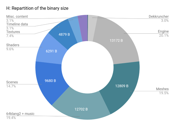
This graph shows how 64KB is occupied by different types of content after compression.

This graph shows the change in binary size (not including approximately 2KB of unpacker) until the final release.
Design and sources of inspiration
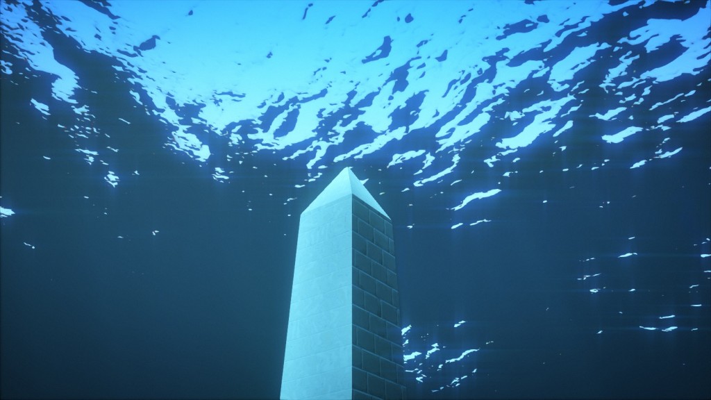
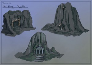
Having agreed that the central theme will be a city immersed in water, we asked ourselves the first question: what should this city look like? Where is it located, why is it flooded, what is its architecture? One simple answer to all these questions: it may be the legendary lost city of Atlandis . This will also explain its appearance: by the will of the gods (literally deus ex machina). On this we decided.

An early concept of a flooded city. The artwork featured in this article was created by Benoît Molenda.
When making design decisions, we were guided by two books: Timaeus and Critius , in which Plato described Atlantis and its fate. In particular, in Critia , he describes in detail the details of the structure of the city, its color, the abundance of precious heirloom (which became an essential element of the scene with the temple), the general shape of the city and the main temple dedicated to Poseidon and Clayto. Since Plato obviously bases his descriptions on the countries he knows, that is, a mixture of Greek, Egyptian and Babylonian styles, we decided to stick to this.
However, without sufficient knowledge of the subject, creating a convincing antique architecture seemed a daunting task. Therefore, we decided to recreate the existing buildings:
- One of them is a reproduction of the Athenian Parthenon .
- Another is a simplified version of the Delphian Tholos .
- When creating the viaduct, we built on the Pont du Gard and the aqueduct in Segovia .
- The temple is essentially the temple of Artemis at Ephesus, one of the Seven Wonders of the World of the Ancient World.
The search for reference materials on the temple of Artemis (Artemision) was unexpected, enriched us with experience. At first, we looked only for photographs, diagrams, or maps. But when we found out the name of John Turtle Wood , everything gained more depth. Wood was the same person who was searching for the location of the temple and as a result found it. Hoping that a search by his name would give us more results than just Artemision, we immediately stumbled upon his book, written in 1877, in which he not only gives descriptions and sketches of the temple, but also describes his eleven-year journey to the lost monument, negotiations with the British Museum about financing, relations with local workers and diplomatic negotiations, without which it was impossible to carry out excavations in arbitrary places.
These books were very important for us to make design decisions, but above all, their reading made us, as individuals, much more appreciated the work on the project.
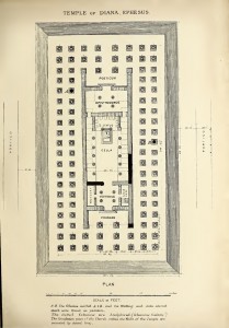
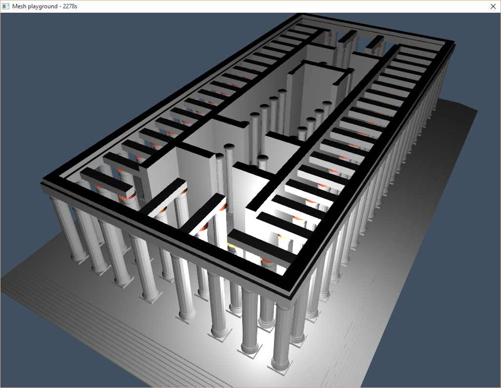

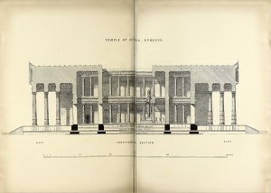
And by the way, what should the roof look like? In some sketches, including Wood, there was a hole in it, in others it was absent; there is obviously some kind of contradiction here. We decided to choose a model with an open roof, which will allow us to illuminate the interior of the castle with a ray of light. The illustrations above show the architectural plan and cross sections of the building from Discoveries at Ephesus , which can be compared with our working model of the temple.
How to achieve the desired appearance
From the very beginning, we knew that the appearance of water would be critical in this intro. Therefore, we spent a lot of time on it, starting with viewing reference materials in order to understand the inherent elements of underwater graphics. As you might guess, we were inspired by James Cameron 's “Abyss” and “Titanic” , 3DMark 11 , and lighting was studied in Ridley Scott 's Blade Runner .
To achieve the correct feeling of being under water, it was not enough to implement and turn on some epic function MakeBeautifulWater (). It was a combination of many effects, which, if properly configured, could convince us, the audience, of the illusion and make us feel like we are under water. But one mistake is enough to destroy the illusion; we learned this lesson too late when we were shown in the comments after the initial release where the illusion disappears.


As can be seen in the illustrations, we also investigated various unrealistic and sometimes excessive palettes, but did not know how to achieve such an appearance, so as a result we returned to the classic color scheme.
Water surface
Water surface rendering involves reflection from a flat surface. Reflection and refraction are first rendered on separate textures using one camera, located on the side, and the second, located above the water plane. In the main passage, the surface of the water is rendered as a mesh with a material that combines reflection and refraction based on the normal and gaze vector. The trick is to shift the coordinates of the textures based on the normal to the surface of the water in the screen space. This technique is classic and well-documented.
On a medium scale, this works well, for example, during a scene with a boat, but on a large scale, for example, in the final scene with the appearance of a temple from the water, the result looks artificial. To make it convincing, we used an artistic trick of applying Gaussian noise to intermediate textures. Blurring the texture of refraction gives the water a gloomy look and a greater sense of depth. Blurring the reflection texture helps the sea look more worried. In addition, applying greater blur in the vertical direction mimics the vertical traces that can be expected from the surface of the water.

The blurry image of the temple is reflected in the surface of the water.
The animation was performed using simple Gerstner waves in a vertex shader by adding eight waves with random directions and amplitude (in a given range). Smaller details are executed in a fragment shader containing 16 more wave functions. The artificial backscatter effect, based on the normal and height, makes the wave peaks brighter, visible in the image above as small turquoise spots. During the launch scene, several additional effects are added, for example, a raindrop shader.
Illustration of a shader. Click on the image to go to the shader in Shadertoy.
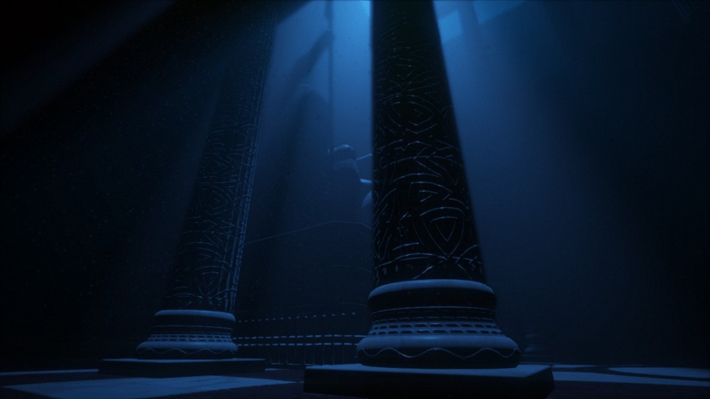
Volumetric lighting
One of the first technical questions was “How to make columns of light submerge in water?” . Perhaps a translucent billboard with a beautiful shader is suitable? Once we started experimenting with naive ray marching through the medium. We were pleased to observe that even in the early rough rendering test, despite poorly selected colors and the lack of a decent phase function, volumetric lighting immediately became convincing. At this moment, we abandoned the original idea with a billboard and never returned to it.
Thanks to this simple technique, we got effects that we did not even dare to think about. When we added a phase function and experimented with it, the sensationsbegan to be like real ones. From a cinematic point of view, this opened up many possibilities. But the problem was speed.

Pillars of light give this scene the look Blade Runner inspired.
It is time to turn this prototype into a real effect, so we read the tutorial by Sebastian Hillar , his presentation of DICE and explored other approaches, for example, with epipolar coordinates . As a result, we settled on a simpler technique close to the one used in Killzone Shadow Fall ( video ) with some differences. The effect is performed by one full-screen shader at half resolution:
- A ray is emitted for each pixel and its interactions with each cone of light are solved analytically.
Mathematical calculations are described here . In terms of performance, it is likely to be more efficient to use a bounding mesh for the volume of light, but for 64K it seemed easier for us to use an analytical approach. Obviously, the rays do not propagate further than depth in the depth buffer. - If the beam intersects for volume inside the cone, ray marching is performed.
The number of steps is limited for speed reasons and random offsets are added to them to avoid lanes. This is a typical case of removing strips for noise, less dubious visually. - At each step, a shadow map is obtained corresponding to the light, and the effect of light is accumulated in accordance with the simple Heny-Greenstein phase function .
Unlike the approach based on epipolar coordinates, using this technique it is possible to have a heterogeneous density of the medium, which adds variability, but we did not realize such an effect. - The resolution of the resulting image is increased using a two-pass bidirectional Gaussian filter and is added over the main rendering buffer. Unlike the technique from the Sebastian tutorial, we do not use temporary re-projection; we only use a sufficiently large number of steps to reduce visible artifacts (8 steps with low quality settings, 32 steps with high quality settings).
Volumetric lighting allows you to give the right mood and a distinctive cinematic appearance, which is difficult to implement otherwise.
Light absorption
An instantly recognizable aspect of the underwater image is absorption. When the object is removed, it becomes less and less visible, its colors merge with the background until it completely disappears. Similarly, the volume influenced by light sources is also reduced, because light is rapidly absorbed by the aquatic environment.
This effect has excellent potential for creating a cinematic sensation, and simulating it is very simple. It is created in two steps in a shader. The first stage applies a simple absorption function to the brightness of light when accumulating light sources that affect the object, thereby changing the color and brightness of the light when it reaches surfaces. The second stage applies the same absorption function to the final color of the object itself, thereby changing the perceived color depending on the distance to the camera.
The code has approximately the following logic:
vec3 lightAbsorption = pow(mediumColor, vec3(mediumDensity * lightDistance));
vec3 lightIntensity = distanceAttenuation * lightColor * lightAbsorption;
vec3 surfaceAbsorption = pow(mediumColor, vec3(mediumDensity * surfaceDistance));
vec3 surfaceColor = LightEquation(E, N, material) * lightIntensity * surfaceAbsorption;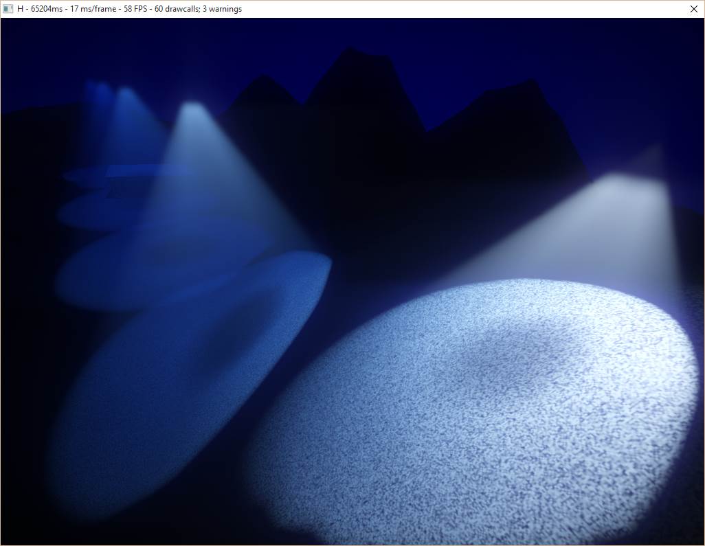
Test of light absorption in the aquatic environment. Notice how color affects the distance to the camera and the distance from light sources.
Adding Vegetation
We definitely wanted to use algae. In the list of desirable typical elements of underwater scenes, they stood in one of the first places, but their implementation seemed risky. Such organic elements can be difficult to implement, and improper implementation can destroy the sense of immersion in illusion. They must have a convincing shape, integrate well into the environment, and possibly require an additional model of subsurface scattering.
However, one day we felt that we were ready for the experiment. We started with a cube, scaled it and arranged a random number of cubes in a spiral around an imaginary stem: from a sufficiently large distance this could pass for a long plant with many small branches. After adding a lot of noise to deform the model, the algae began to look almost decent.
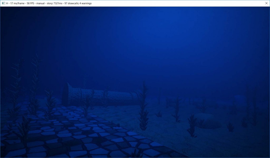
Test frame with few rare plants.
However, when we tried to add these plants to the scene, we realized that with an increase in the number of objects, the speed decreases rapidly. Therefore, we could add too few of them to make it look convincing. It seems that our new non-optimized engine has already stumbled upon the first “bottleneck”. Therefore, at the last minute, we implemented coarse clipping along the pyramid of visibility (the correct clipping is used in the final version), which allowed us to show dense bushes in the demo.
With a suitable density and size (areas with a normal distribution), and when the details are hidden by dim lighting, the picture begins to look interesting. In further experiments, we tried to animate algae: the noise function for modulating the strength of an imaginary underwater current, the inverse exponential function for the plants to bend, and the sine wave to twist the tips in the stream. During the experiments, we came across a real treasure: the emission of underwater light through the bushes , drawing on the seabed shadow patterns that disappear when removed from the camera.

Vegetation casting shadow patterns on the seabed.
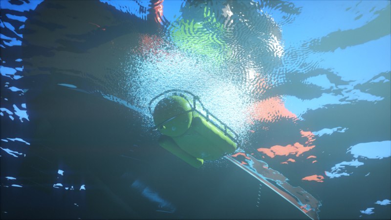
Particle Injection
The final touch is particles. Look carefully at any underwater survey, and you will notice all kinds of suspended particles. Stop paying attention to them, and they will disappear. We set up the particles so that they were barely noticeable and did not come in the way. However, they give a sense of volume filled with a tangible medium, and help strengthen the illusion.
From a technical point of view, everything is quite simple: in the Immersion intro, particles are just instances of quadrangles with translucent material. We simply avoided the problem of rendering order caused by translucency by setting the position along one axis in accordance with the instance identifier. Due to this, all instances are always drawn along this axis in the correct order. For each frame, then you need to properly orient the volume of particles. In fact, for many frames of this, we did not do this at all, because the particle size and darkness of the scene made noticeable artifacts quite rare.

In this frame, the particles give a concept of depth and a sense of density with increasing immersion depth.
Music
How to fit high-quality music in about 16KB? This task is not new, and most of the 64k intros written after .the .product of 2000 use similar concepts. The original series of articles is quite old, but does not lose its relevance: The Workings of FR-08's Sound System .
In short, the idea is that we need a musical score and a list of instruments. Each of the instruments is a function that generates sound procedurally (see, for example, subtractive synthesis and synthesis of physical modeling) A musical score is a list of notes and effects used. It is stored in a format similar to midi, with some modifications to reduce the size. Music generation occurs during program execution.
The synthesizer also has a plug-in version ( VSTi ), which the musician can use in his favorite music composing program. After composing the music, the composer presses a button that exports all the data to a file. We embed data in a demo.
When the demo starts, it launches a stream to generate music in a huge buffer. The synthesizer actively consumes CPU resources and is not necessarily executed in real time. Therefore, we start the stream before the demo starts, when textures and other data are generated.
Daniel Lindholm composed the music using the 64klang synthesizer created by Dominic Riesz.
The working process
When creating a demo, one of the most critical aspects is the iteration time. In fact, this applies to many creative processes. Iteration time is the most important. The faster you can iterate, the more you can experiment, the more variations you can explore, the more you can improve your vision and improve quality in general. Therefore, we want to get rid of all obstacles, pauses and small friction in the process of creativity. Ideally, we want to be able to change anything and anytime, instantly seeing the result and getting continuous feedback in the process of making changes.
Possible solution used by many demo groups, is to build the editor and create all the content inside it. We did not do this. Initially, we wanted to write C ++ code and do everything inside Visual C ++. Over time, we developed several techniques to improve our workflow and reduce the iteration time.
Hot reload all data
If we could give only one piece of advice in this article, it would be like this: make sure that all your data supports hot reloading. All data . Make it so that you can detect data changes, download new data when this happens, and change the state of the program accordingly.
Little by little, we made it possible to hot-load all the data: shaders, cameras, editing, all time-dependent curves, etc. In practice, we usually had an editor and an additional demo launched. When a file was modified, the changes instantly became visible in the demo.
In such a small project as a demo, this is easy to implement. Our engine monitors where the data comes from, and a small function regularly checks for changes in the time stamps of the corresponding files. When they are changed, it starts a reboot of the corresponding data.
Such a system can be much more complex in large projects in which such changes are hindered by dependencies and legacy structure. But the influence of this mechanism on the production process is difficult to overestimate, so it is completely worth the investment.
Custom values
Data reloading is, of course, good, but what about the code itself? It’s more and more difficult with him, so we had to solve this problem in stages.
The first step was a tricky trick that allowed us to modify constant literals. Joel Davis described this in his post : a short macro that turns a constant into a variable with a piece of code that recognizes the change in the source file and updates the variable accordingly. Obviously, this auxiliary code is missing from the final binary file and only a constant is left. Thanks to this, the compiler is able to perform all optimizations (for example, when a constant is assigned the value 0).
This trick may not be applicable in all cases, but it is very simple and can be integrated into code in minutes. Moreover, although it is understood that it should only change the constants, it can also be used for debugging: to change code branches or enable / disable parameters with conditions like if (_TV (1)) .
Recompiling C ++
Finally, the very last step to ensure code flexibility was to include the Runtime Compiled C ++ tool in the code base . It compiles the code as a dynamic library and loads it, and also performs serialization, which allows you to make changes to this code and observe the results during execution, without having to restart the program (in our case, a demo).
This tool is not perfect yet: its API is too embedded in the code and limits its structure (classes must be derived from the interface), and compiling and reloading the code still takes several seconds. Nevertheless, the ability to make changes to the code logic inside the demo and see the result provides wide creative freedom. At the moment, the advantages of the tool are used only for texture and mesh generators, but in the future we want to expand its work to the entire set of code dealing with content.
To be continued
This ends the first part of what is intended as a series of articles on the techniques used in the development of H - Immersion. We would like to thank Alan Wolf for proofreading the article; there are many interesting technical articles on his blog . In the following parts, we will talk more about how textures and meshes are created.