OMower with ROS, first steps
Initially, OMower was developed for the simple control interfaces pfodApp and Modbus. The first is a high-level text protocol in which menus and control commands are transmitted, and the second is a well-known, but not very convenient thing in this application, as it requires the control program to constantly poll the state of all the sensors used manually. Therefore, it was decided to gradually move to ROS (Robot OS), a widely used framework for controlling various robots.
At the moment, ROS support is in its initial stages, including only the transfer of information from sensors in the form of simple arrays (without using specialized message formats offered by many ROS libraries), the debug log and control command streams in pfodApp / Modbus format, without the possibility really control the robot using standard ROS tools. That is, to move the robot from its place or change any internal configuration of the robot, you will need to send a text command in pfodApp format to it. But even in such a truncated form - you can easily broadcast and record what is happening with the robot, visualizing its movements in standard ROS (rviz) tools, as well as adding services for additional functions. Such, for example, provided by omower_seeker.
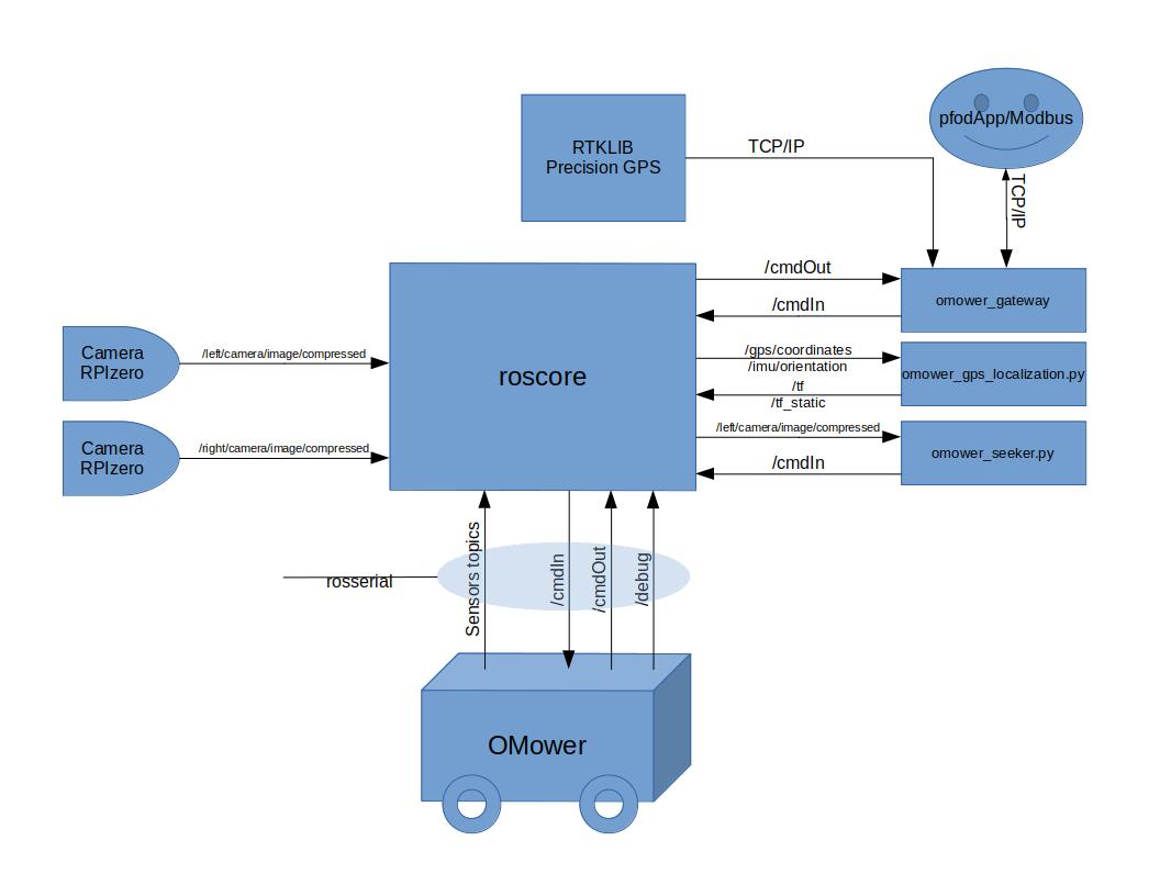
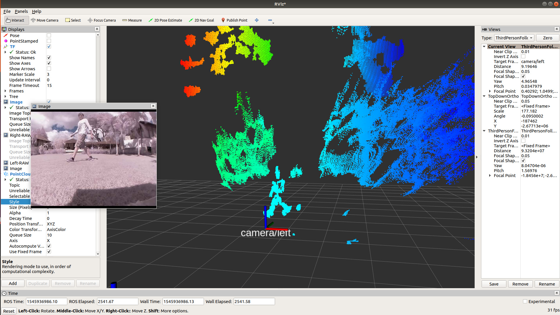
The picture shows data streams in the robot. The main ROS services are executed on Orange PI Zero, stuck in a special slot on the robot's board (on a test machine, the Raspberry PI3 is used for this, connected in a similar way - via a serial port). Through the rosserial interface - the robot sends to the ROS core messages from sensors (such as / imu / orientation or / motors / PWM), its debug log in text format and display of menu / messages in pfodApp or Modbus format, receiving a stream of text commands or Modbus -queries. From two additional Raspberry PI Zero, streams of pictures from cameras come, but as practice has shown, it is impossible to get normal synchronization for processing stereo images with such a scheme (the quality can be seen in the picture below), so soon you will be replaced with a normal stereo camera.
The degree of integration of ROS in OMower will gradually expand, up to providing full access to all internal variables of the robot and the ability to manage it through standard ROS tools (such as cmd_vel-messages defining the desired speed of movement).
I'll tell you a little more about the module omower_seeker.py, as an example of using ROS to add functions to OMower. His appointment is quite simple - to go in the direction of the chessboard, adjusting your route in real time. This feature will be used to drive a lawnmower to a parking station, where it can quickly charge its batteries. Analyzing the image from one of the cameras, the module calculates two angles (the angle of deflection of the board from the center of the camera and the angle of rotation of the board itself relative to the perpendicular) and transmits them as a text command to the internal seeker module (omower-seeker.h / cpp in the OMower SDK).
Outwardly, this looks like a fairly simple task, but in real life there is a serious problem - the speed of image processing on the microcomputer built into the robot. As practice shows, the pattern search speed in opencv on the image when using relatively low-powered Orange PI and Raspberry Pi is very low and unstable, taking from tens to hundreds of milliseconds with a resolution of 640x480, which during the ride turns into deviations from the required route, since the robot , even with its low speed, during this time it manages to turn a significant angle or travel a relatively large distance. Actually, this is why a chessboard with a minimum of cells was chosen, since other templates take even more time.
To compensate for the long search time of the visual template, a scheme using a compass is used — the robot microcontroller saves its values every 100 milliseconds, storing five counts in the last half of a second (longer analyzes are simply discarded, due to their poor suitability for precise navigation). The calculated angles from omower_seeker.py (which also transfers the pattern search time to the microcontroller) are recalculated into the actual rotation angle using the saved compass value, which is no more than 100 milliseconds from the search time, and the robot travels along this angle. This allows you to more or less accurately go in the direction of the chessboard in a straight line. Or, if it is slightly rotated relative to the perpendicular - in an arc, correcting the angle of approximation so that it is as close as possible to the template axis,
The full algorithm of arrival at the station is implemented in three stages. Two points are set on the GPS field - the starting point (somewhere in the middle of the work area), and a point in front of the station, as well as the angle of rotation to the station. After the robot arrives from the starting point to the second and turns to the desired angle in the direction of the chessboard at the station, the seeker module comes into play, adjusting the engine speed via the PID controller. If any of the stages fail, or the deviation angles exceed the specified values - the robot cancels the race and returns to the starting point again.
Links and videos:
→ OMower SDK, library for Arduino IDE and circuit diagram with PCB layout
→ Ready firmware using SDK that implements both pfodApp / Modbus and connection to ROS
→Package omower_gateway for ROS
At the moment, ROS support is in its initial stages, including only the transfer of information from sensors in the form of simple arrays (without using specialized message formats offered by many ROS libraries), the debug log and control command streams in pfodApp / Modbus format, without the possibility really control the robot using standard ROS tools. That is, to move the robot from its place or change any internal configuration of the robot, you will need to send a text command in pfodApp format to it. But even in such a truncated form - you can easily broadcast and record what is happening with the robot, visualizing its movements in standard ROS (rviz) tools, as well as adding services for additional functions. Such, for example, provided by omower_seeker.
The picture shows data streams in the robot. The main ROS services are executed on Orange PI Zero, stuck in a special slot on the robot's board (on a test machine, the Raspberry PI3 is used for this, connected in a similar way - via a serial port). Through the rosserial interface - the robot sends to the ROS core messages from sensors (such as / imu / orientation or / motors / PWM), its debug log in text format and display of menu / messages in pfodApp or Modbus format, receiving a stream of text commands or Modbus -queries. From two additional Raspberry PI Zero, streams of pictures from cameras come, but as practice has shown, it is impossible to get normal synchronization for processing stereo images with such a scheme (the quality can be seen in the picture below), so soon you will be replaced with a normal stereo camera.
The degree of integration of ROS in OMower will gradually expand, up to providing full access to all internal variables of the robot and the ability to manage it through standard ROS tools (such as cmd_vel-messages defining the desired speed of movement).
I'll tell you a little more about the module omower_seeker.py, as an example of using ROS to add functions to OMower. His appointment is quite simple - to go in the direction of the chessboard, adjusting your route in real time. This feature will be used to drive a lawnmower to a parking station, where it can quickly charge its batteries. Analyzing the image from one of the cameras, the module calculates two angles (the angle of deflection of the board from the center of the camera and the angle of rotation of the board itself relative to the perpendicular) and transmits them as a text command to the internal seeker module (omower-seeker.h / cpp in the OMower SDK).
Outwardly, this looks like a fairly simple task, but in real life there is a serious problem - the speed of image processing on the microcomputer built into the robot. As practice shows, the pattern search speed in opencv on the image when using relatively low-powered Orange PI and Raspberry Pi is very low and unstable, taking from tens to hundreds of milliseconds with a resolution of 640x480, which during the ride turns into deviations from the required route, since the robot , even with its low speed, during this time it manages to turn a significant angle or travel a relatively large distance. Actually, this is why a chessboard with a minimum of cells was chosen, since other templates take even more time.
To compensate for the long search time of the visual template, a scheme using a compass is used — the robot microcontroller saves its values every 100 milliseconds, storing five counts in the last half of a second (longer analyzes are simply discarded, due to their poor suitability for precise navigation). The calculated angles from omower_seeker.py (which also transfers the pattern search time to the microcontroller) are recalculated into the actual rotation angle using the saved compass value, which is no more than 100 milliseconds from the search time, and the robot travels along this angle. This allows you to more or less accurately go in the direction of the chessboard in a straight line. Or, if it is slightly rotated relative to the perpendicular - in an arc, correcting the angle of approximation so that it is as close as possible to the template axis,
The full algorithm of arrival at the station is implemented in three stages. Two points are set on the GPS field - the starting point (somewhere in the middle of the work area), and a point in front of the station, as well as the angle of rotation to the station. After the robot arrives from the starting point to the second and turns to the desired angle in the direction of the chessboard at the station, the seeker module comes into play, adjusting the engine speed via the PID controller. If any of the stages fail, or the deviation angles exceed the specified values - the robot cancels the race and returns to the starting point again.
Links and videos:
→ OMower SDK, library for Arduino IDE and circuit diagram with PCB layout
→ Ready firmware using SDK that implements both pfodApp / Modbus and connection to ROS
→Package omower_gateway for ROS