Arduino Brain: Pulse Position Sensor
- Tutorial
Today's challenge: how to determine the rotation angle of an incremental encoder?
Today, in a series of publications about brain arduino, a short article with a little experiment and a couple of recipes. In the comments on one of my past articles, I was accused of counting the encoder pulses with an arduino - do this:
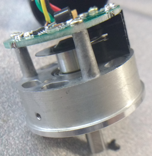
Optical encoder 1000 / revolution and ATMega that does not have a hardware circuit for working with the encoder (like the STM32 series, for example) is a dead end.Further in the comments there was a lot of theorizing, which is better to skip. Let's better try to test in hardware how deadlock this is. For starters, what is an incremental encoder? Anyone who remembers the era of pre-optical mice knows the answer for sure. Inside the encoder there is a disk with slots, so for clarity, I took a photo of a disk with five hundred slots:

On one side of this disk, an LED is placed, on the other a photodiode:
Rotating, the disk then passes light to the photodiode (if the slot is opposite the pair of LED-photodiode), it does not pass. At a constant speed of rotation at the output of the photodiode, a beautiful sinusoid is obtained (do not forget that the light stream can be partially blocked). If this signal is passed through the comparator, then a rectangular signal will be obtained. Counting the number of pulses of the signal, we get how much the sensor shaft is turned.
How is the direction of rotation determined? Very simple: the sensor has not one, but two pairs of LED-photodiode. Let's draw our disk, points A and B show the position of the photosensors. When rotating the encoder shaft, we remove two signals from these photosensors:
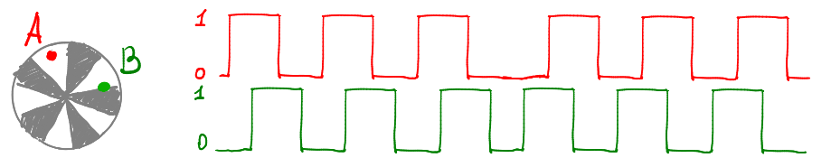
The sensors are set at such a distance that, when rotating at a constant speed, a meander is generated, twisted for a quarter of a period. This means that when the photosensor A is opposite the middle of the slot, the photosensor B is exactly at the boundary of the slot. When the sensor rotates (conditionally) clockwise, then with an rising edge on signal B, signal A is equal to one. When the sensor rotates in the opposite direction, then with an ascending edge, the signal B a is equal to zero.
All this is fine, but what should I copy-paste into my project?
This:
volatile long angle = 0;
volatile char ABprev = 0;
const int increment[16] = {0,-1,1,0, 1,0,0,-1, -1,0,0,1, 0,1,-1,0};
ISR (PCINT0_vect) { // D8 or D9 has changed
  char AB = PINB & 3;
  angle += increment[AB+ABprev*4];
  ABprev = AB;
}
void setup() {
  pinMode(8, INPUT);  // A
  pinMode(9, INPUT);  // B
  PCICR |= (1 << PCIE0);  // interrupt will be fired on any change on pins d8 and d9
  PCMSK0 |= 3;
  ABprev = PINB & 3;
  Serial.begin(115200);
}
void loop() {
  Serial.println(angle);
  delay(100);
}
Let's explain how this code works. I am testing the code on ATmega328p (Arduino nano), the encoder outputs are set to pins d8 and d9 of the arduino nano. In terms of ATmega328p, this means that the lower two bits of the PINB port give the current state of the encoder. The ISR function will be called upon any change in these two bits. Inside the interrupt, I save the state of the encoder to the variable AB:
  char AB = PINB & 3; // Внимание, ардуиновский digitalRead() противопоказан,
                  // когда нам критична скорость работы
For what? Let's look at the previous chart, in it the dashed lines indicate the moments of the interrupt call (any front on any signal). For each interrupt call, the number at the bottom is the state of the variable AB:
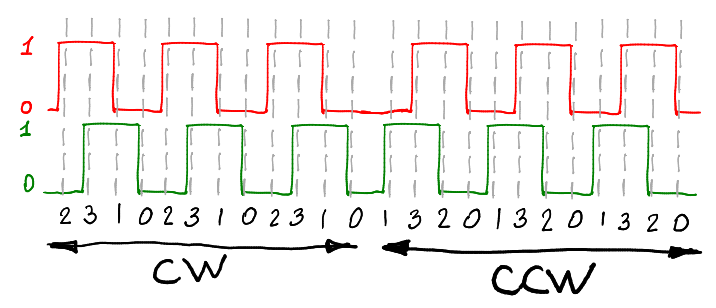
It can be seen that when turning clockwise, the variable AB changes with a period of four values: 2310 2310 2310. When rotating counterclockwise, the variable AB changes 0132 0132 0132.
If we have both photo sensors were blocked (variable AB = 0), and when the interrupt is called, AB becomes equal to 2, then the sensor rotates clockwise, add one to the counter. If AB goes from 0 to 1, then the sensor rotates counterclockwise, subtract one from the counter. The same thing with other changes to the variable AB, let's create a table:
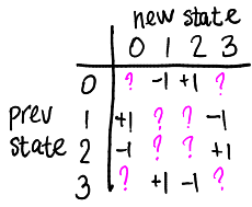
Please note that the table is not completely filled. What to insert in place of question marks? For example, in theory, the main diagonal of the table should never be used, an interrupt is called when the variable AB is changed, so the transition 0-> 0 should not happen. But life is hard, and if the microcontroller is busy, then it can skip several interruptions and still be called. In this case, I propose not adding or subtracting anything, since we obviously lack data; fill the missing cells with zeros, here is our table:
const int increment[16] = {0,-1,1,0, 1,0,0,-1, -1,0,0,1, 0,1,-1,0};
Now, I hope the code is fully understood.
As a result, four interrupts are caused for one period of signal A, which, when the sensor rotates in one direction, will increase the counter not by 1, but by 4. That is, if 2000PPR is written on the incremental encoder (two thousand slots on the disk), then its real resolution is 1/8000 turnover.
Wait, what about the bounce?
Passing a sinusoid through the comparator, we will inevitably get a bounce on the edges of our square waveform. Let's take a magnifying glass and look at one of the fronts:
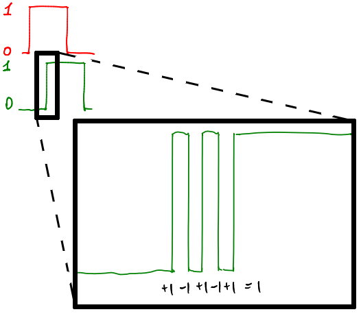
Signal A is constant, so according to our plate, on the rising edge of signal B, we add one, and subtract on the falling edge. As a result, if we can work out all the fronts of our bounce, then our algorithm will swallow it perfectly. And here it becomes interesting, but can our arduinka work out such charms? You can theorize for a long time, let's experiment.
From theory to practice
We will count pulses in three ways:
- Software on ATmega328p
- ATmega328p interrogating a hardware counter
- Beagle bone blue
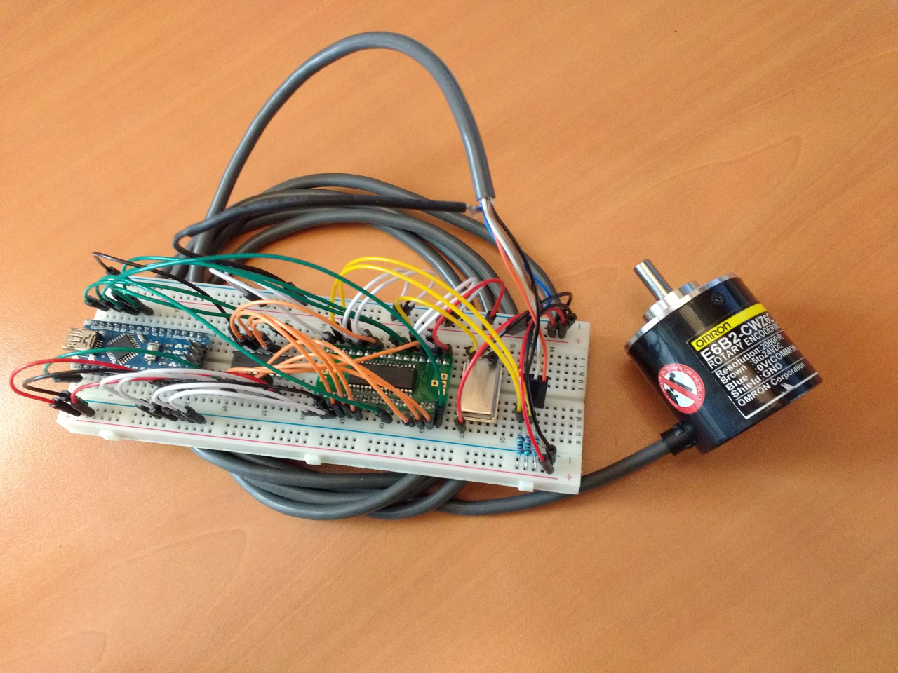
All three methods count pulses in exactly the same way, but, of course, hardware methods have a significantly higher signal polling speed. The encoder is used by the Omron E6B2-CWZ6C (2000PPR).
Connection
Software counter
The connection is simple, it is enough to bring two wires from the encoder to the feet of d8 and d9 arduins.
HCTL-2032
Connecting the hctl-2032 to the arduino looks something like this:
In order not to occupy all the legs of the arduins, I put another 74hc165.
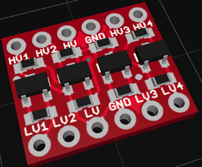
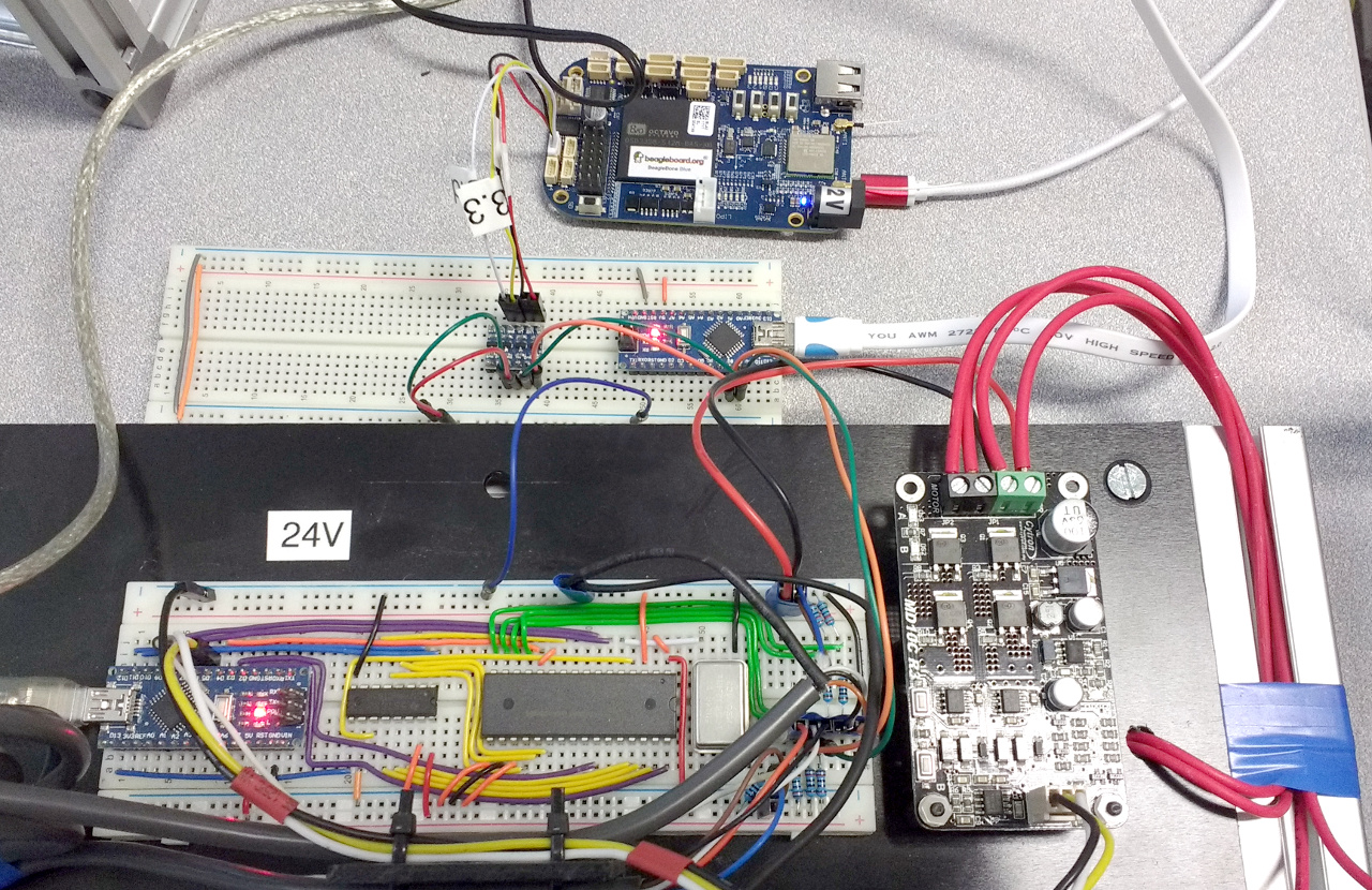
Beagle bone blue
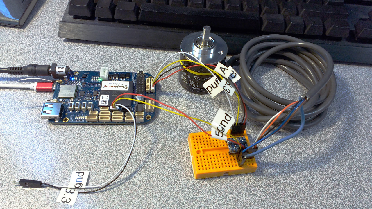
BeagleBone Blue has a built-in quadrature decoder, so 3.3V encoders can simply be connected to the appropriate connector. My encoder has 5V logic, so I added a two-way level converter to bss138 :
Experiment one
I took my stand with a pendulum, which I already described : The
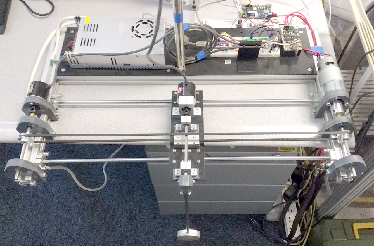
carriage will not travel, I just hang three counters on the pendulum encoder. Why exactly the pendulum? Because gravity gives a non-sagging marker: every time the pendulum calms down, the counters should show a multiple of 8000 (I have an encoder 2000ppr).
Here are three counters connected in parallel, from top to bottom: bigbon, software counter, hctl2032. The PWM driver for the carriage motor is not used in this test:
Start of testing, the pendulum is stationary, two serial port monitors and a beagle counter running via ssh:

I make one complete turn of the pendulum with my hand, wait for it to calm down again in the lower position:
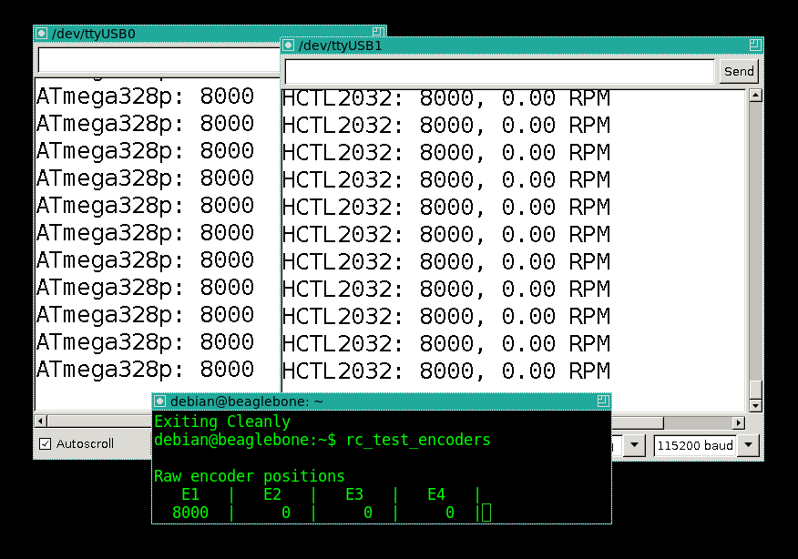
All three counters show exactly 8000, as expected! Well, from the comments we learned that because of the bounce, the software counter should be very wrong at low speeds of the pendulum. I repeat the procedure ten times: I swing the pendulum so that it makes one revolution, and then wait until it completely calms down. Then I shake it again, wait until it calms down. Friction is low, one iteration takes a couple of minutes, as a result, about half an hour of counters work.
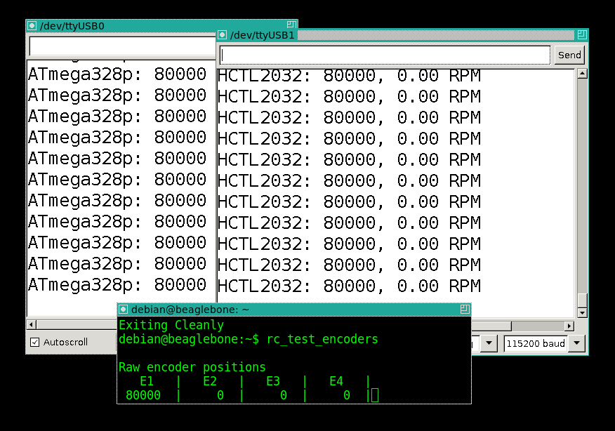
Ha, but again, no one was wrong!
Second experiment
So, the bounce in reality was not as scary as it seemed. I take off the pendulum and hook it to the axis of the encoder screwdriver:
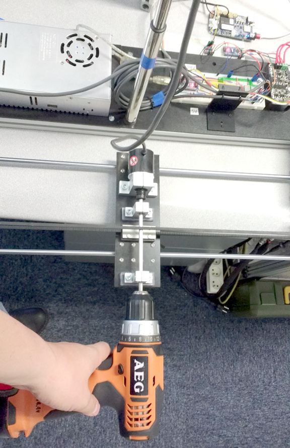
Then slowly increase the speed, stopping periodically, and checking how all three counters agree with what is happening. That is why in one of my windows I have an estimate of the speed of rotation of the encoder shaft.
100 rpm - an order. 500 rpm - order, full agreement. 900 rpm: AHA! I stop the screwdriver:
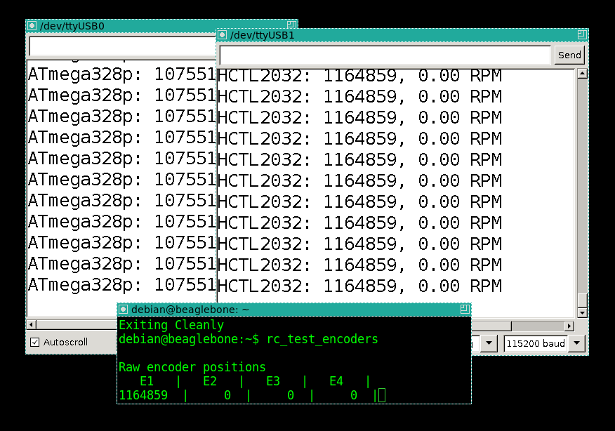
Hardware counters still agree, but software decently lagged behind. Let's consider how this is consistent with theory. The ATmega328p manual says that processing an (empty) interrupt is a minimum of 10 clock cycles of the microcontroller. Working with the stack, a little code inside the interrupt - this is a total of 40 clock cycles per interrupt. 8000 thousand interrupts at 900 revolutions per minute (15 revolutions per second) for 40 cycles = 4800000 cycles per second. In general, our estimate is not far from the clock frequency of the arduino, that is, 1000 revolutions per minute - this is the ceiling for the counter of the high-resolution encoder for interrupts, and for the arduino, which does nothing else.
At 2000 rpm, both hardware counters worked without a mismatch, and I can’t give out a screwdriver anymore.
Summarize:
1. It is quite possible to count on interrupts, 15 revolutions per second - this is still a very decent speed. But if you need to process more than one counter, everything becomes sharply worse. The choice of an encoder plays a strong role, since in good encoders, chatter suppression is inside, so a good encoder and a penny 8-bit microcontroller is quite a solution.
2. Hardware counters are more reliable, but more expensive.
3. hctl2032 is significantly cheaper than BeagleBone Blue, but it is also more difficult to connect to the controller, and the beagle and the controller itself, and is able to process four encoders at once. Yes, and an amplifier for the engine is already there on board, so a stand with a pendulum can be assembled with generally little blood. On the other hand, even being quite exotic, hctl-2032 costs five dollars apiece, and can save the situation when there is already a circuit with some kind of peak or atmel, and you don’t want to change it much.
4. They say stm32 is cheap and has a hardware counter. But the price of entering (in the sense of time) into the question painfully bites.
In general, as usual, there is no ideal solution, it all depends on the task and the available resources.