We are building a data center. Module 3. Part 1. Installation of the first ASU, installation of ShchR
Hello again, Habr! We open a series of articles-photo reports on the construction of our new MCOD Module 3 !
Let's start with a report on the installation of ASUs and consumer shields.
Achtung! A lot ofcrappy photos under the cut!
I humbly ask you to forgive me for a number of vertical photographs.
1. ASU-3.1. Section No. 1
2. VRU-3.1. Section No. 3
3. ЩР-1/2
4. Current construction progress
In Module 3, this time, we use fully solutions from ABB .
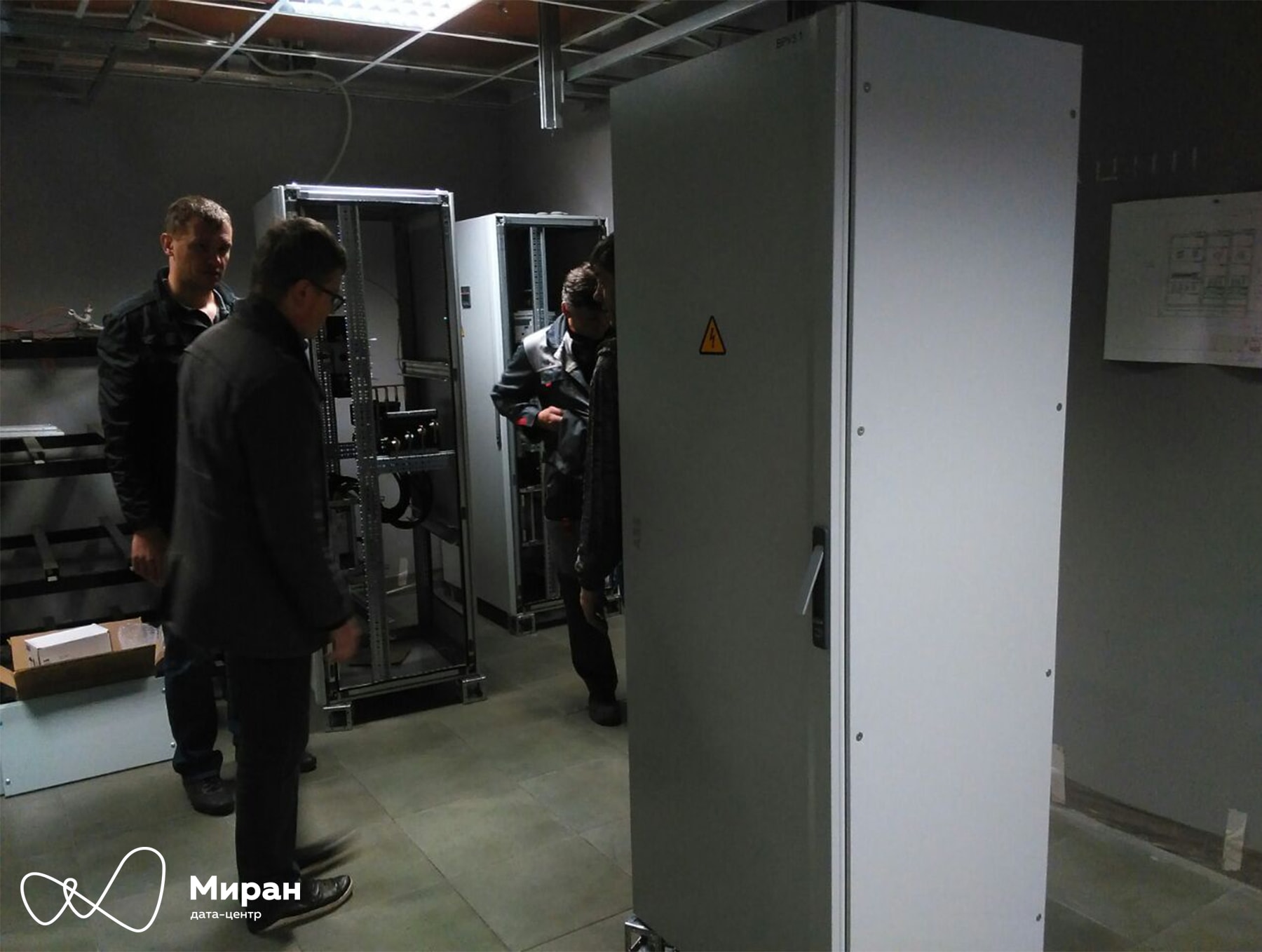
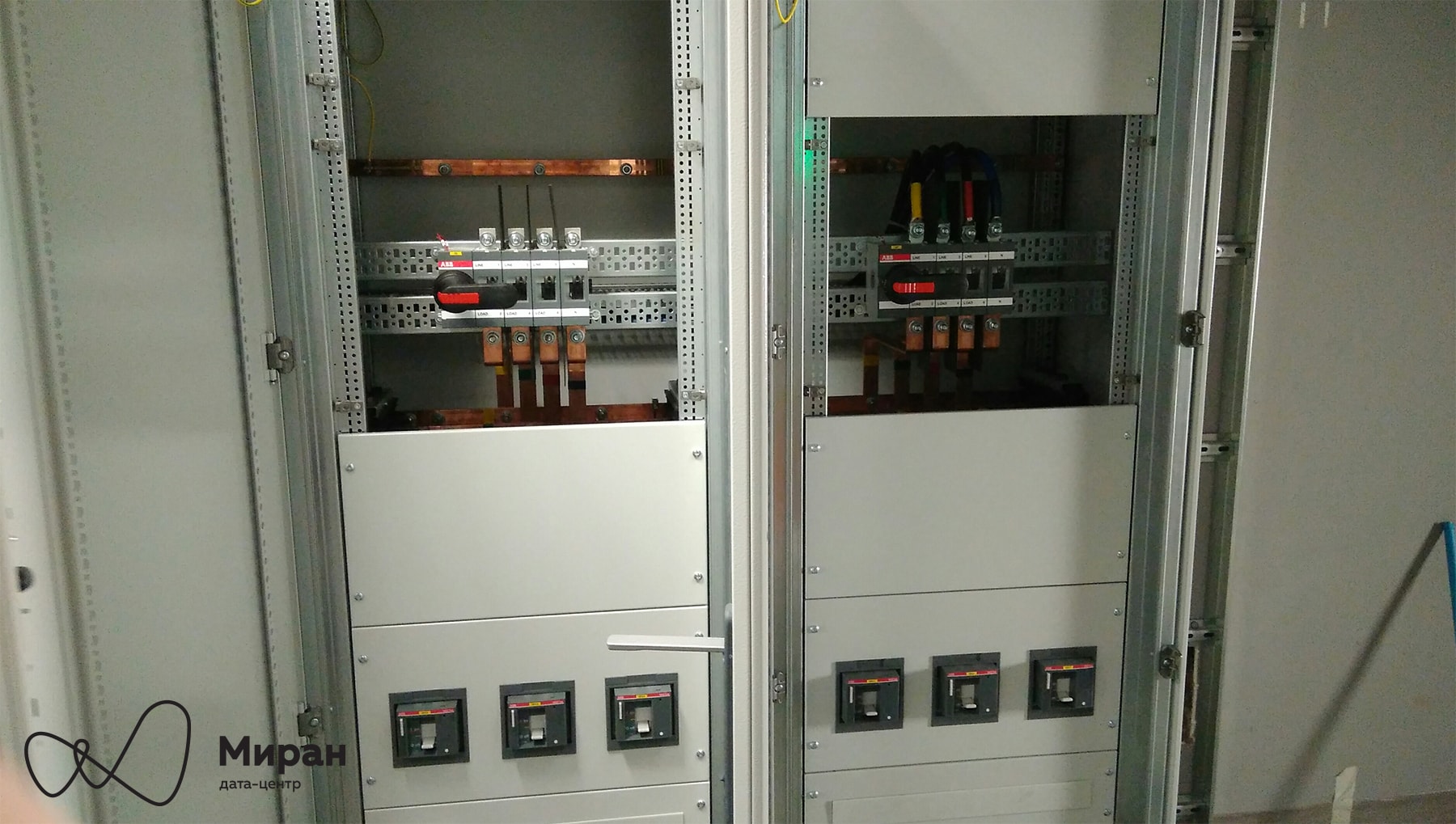
In Module No. 1 and Module No. 2, there were shields with filling from Schneider Electric . Newly arrived sections of the shield VRU-3.1 for Module No. 3. Clickable So far, we have acquired one of the two planned ASUs . The main idea of having two ASUs is redundancy and the possibility of various switching in switchboards without interrupting the power supply to consumers. General view of section No. 1 of VRU-3.1, as well as a view without plastrons. Clickable Two circuit breakers with a rating of 400 A - both under the control of ATS. Separately, it is worth noting that inside the shield itself there is no division of the section into two parts and no sectional switch between them, as was implemented in the ASU of the first two MCODs. Introductory machine

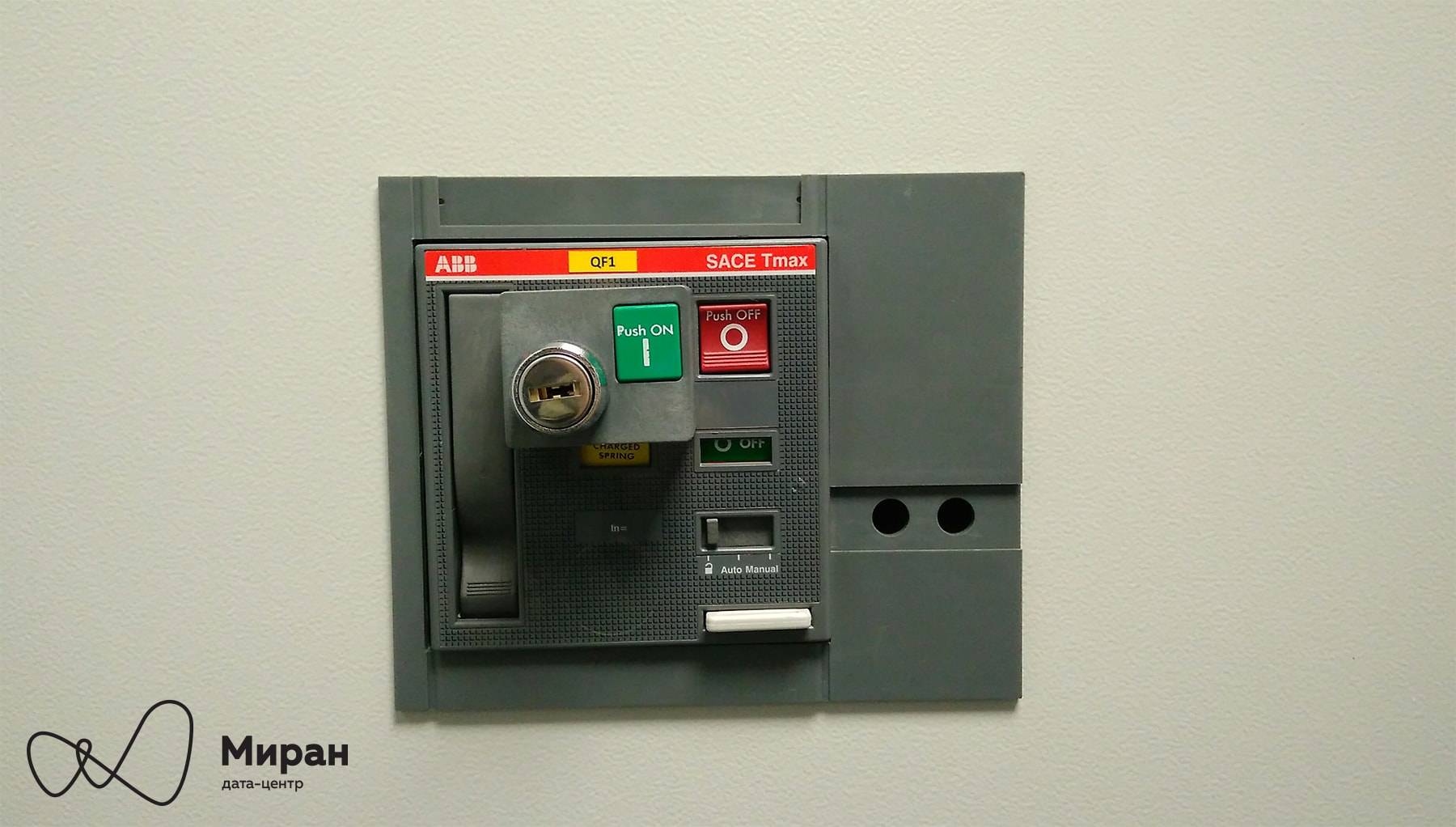
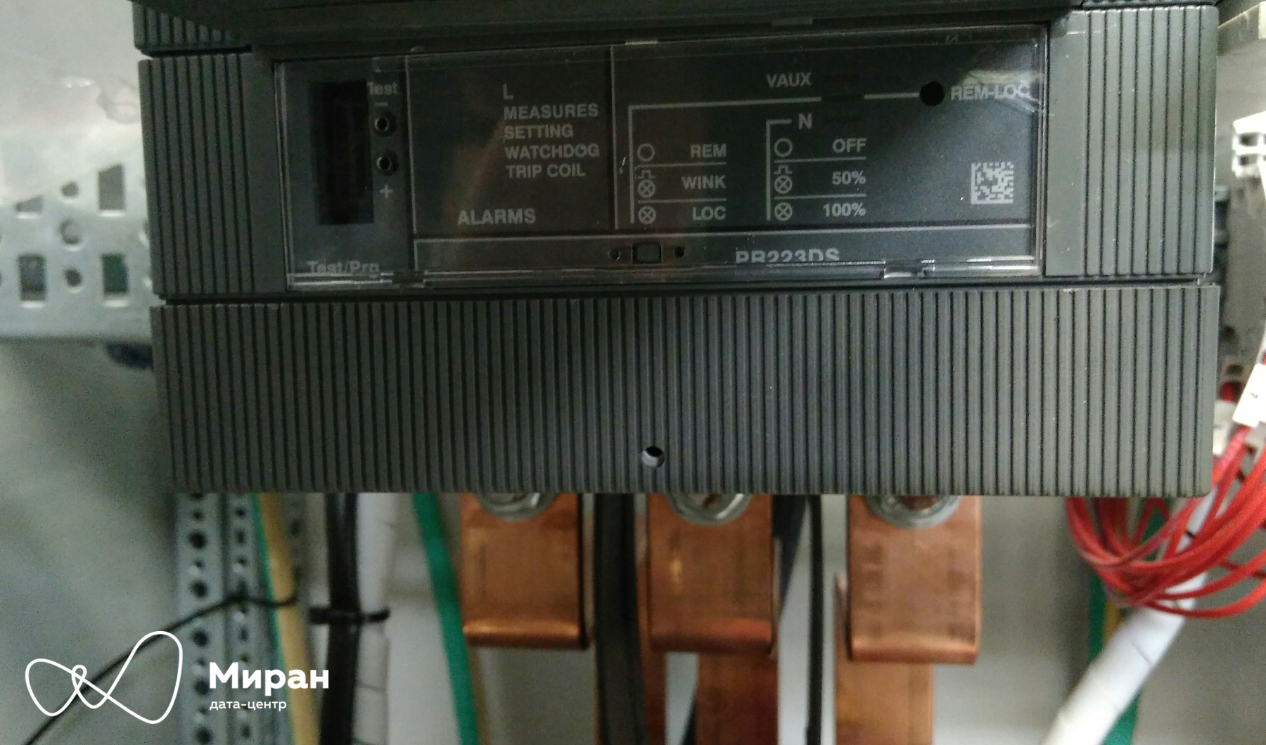
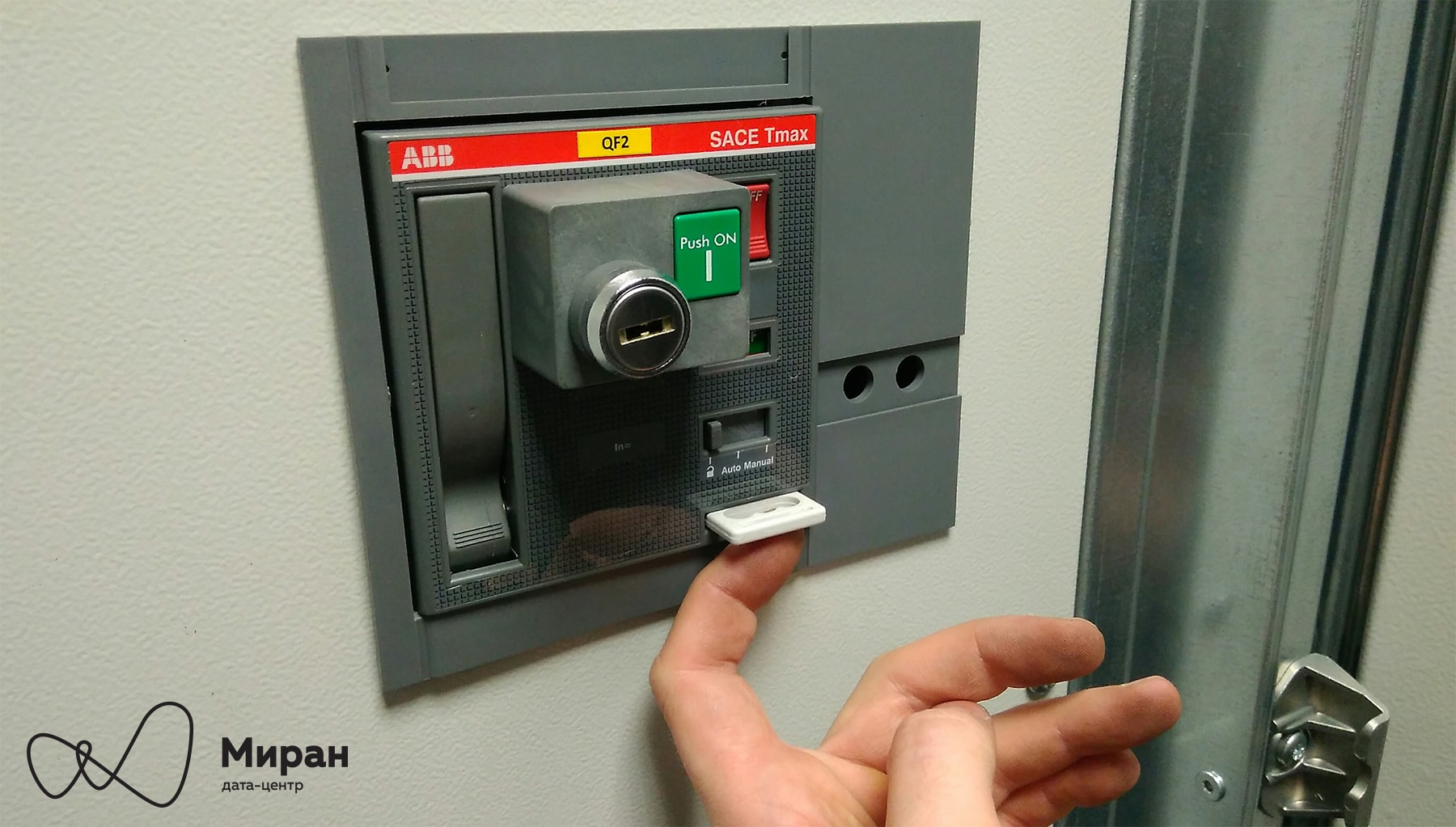
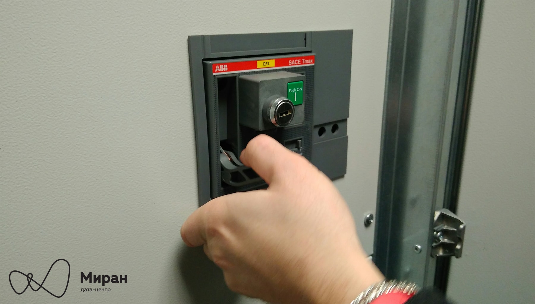
Tmax T5 in withdrawable version. Gearmotor MOE-E . Castle. ASU-3.1. Clickable Electronic release of the introductory machine PR223DS . Clickable In addition to traditional protection, the trip units measure current. These data, as well as data on the state of the machine via Modbus-RTU, will be transmitted to the dispatch system. Bracket for padlocks. Introductory machine. ASU-3.1. Clickable Manual spring loading . Introductory machine. ASU-3.1. Clickable ABP ATS 022 . ASU-3.1. Clickable
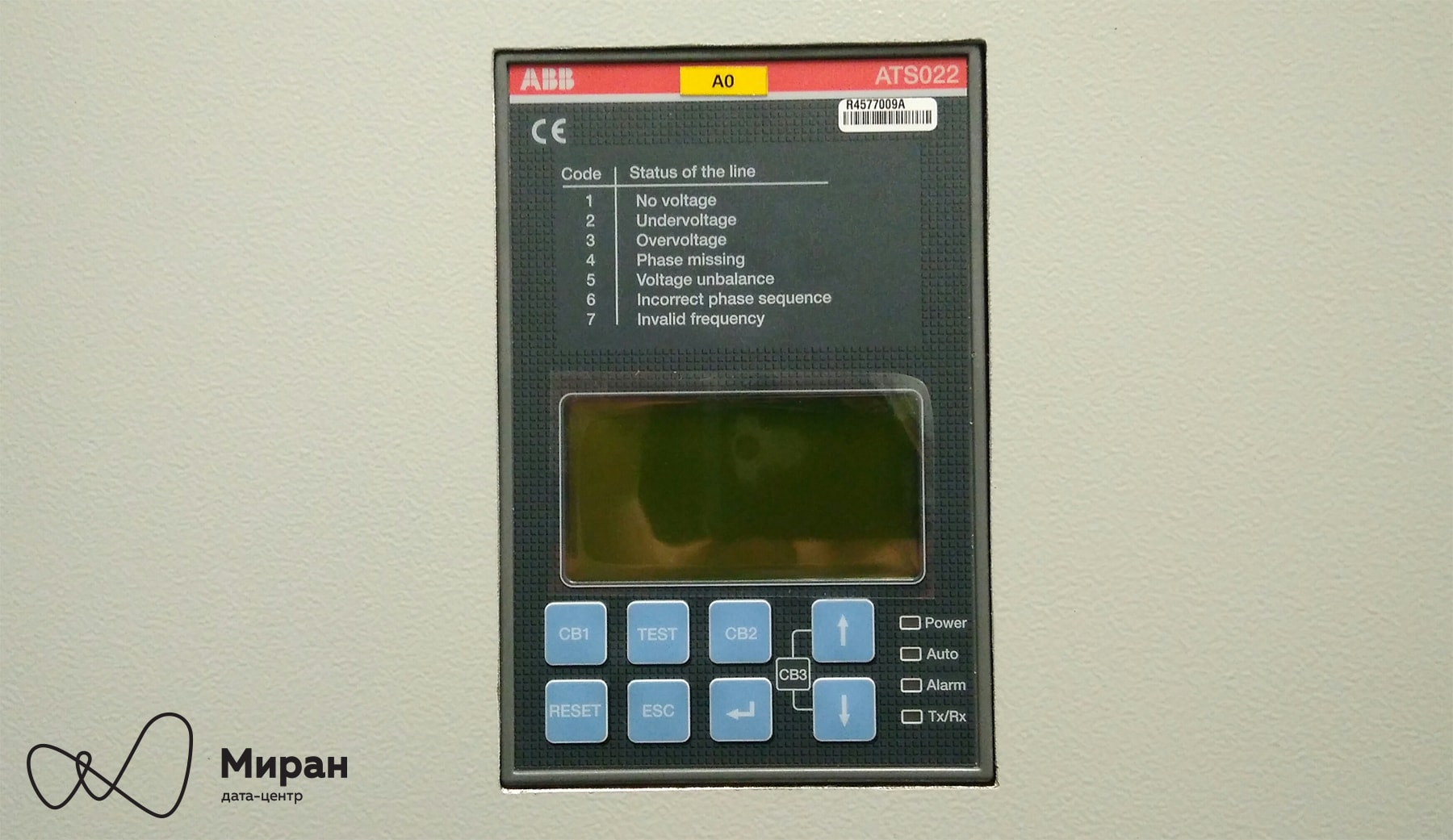
And here is ABP3.1. This is the first time we encounter this iron in the data center, unlike automatic machines. ATS is quite smart, plus it itself measures the voltage and related parameters on the main input buses. Based on whether there is voltage or not, the ATS will make a decision on the closing / opening of the machines. Measured data on Modbus-RTU will also go to the dispatch system. Automatic Tmax T4N , nominal 250 A. Cables are mounted. Clickable The main purpose of the QF1.1-1.2 machines is to provide power to the main and baypass inputs of the UPS-1. The QF1.3 machine feeds section No. 3 through the second QS switch . Machine QF1.4
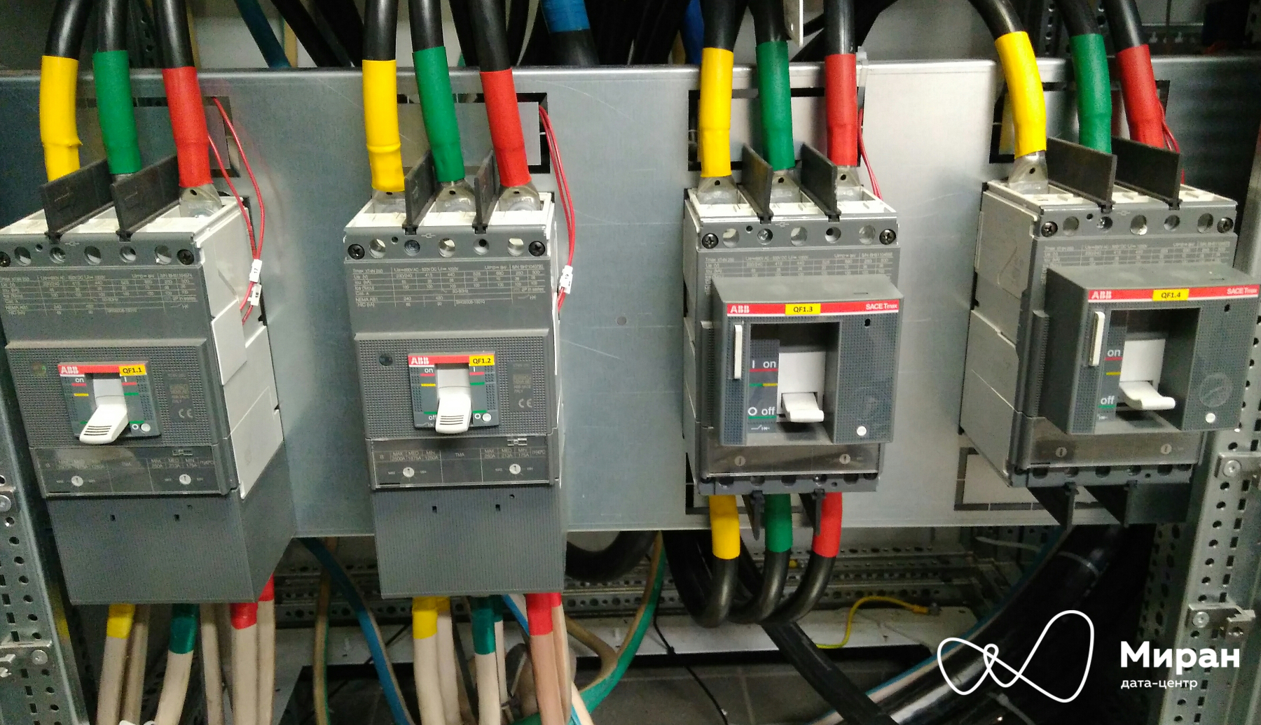
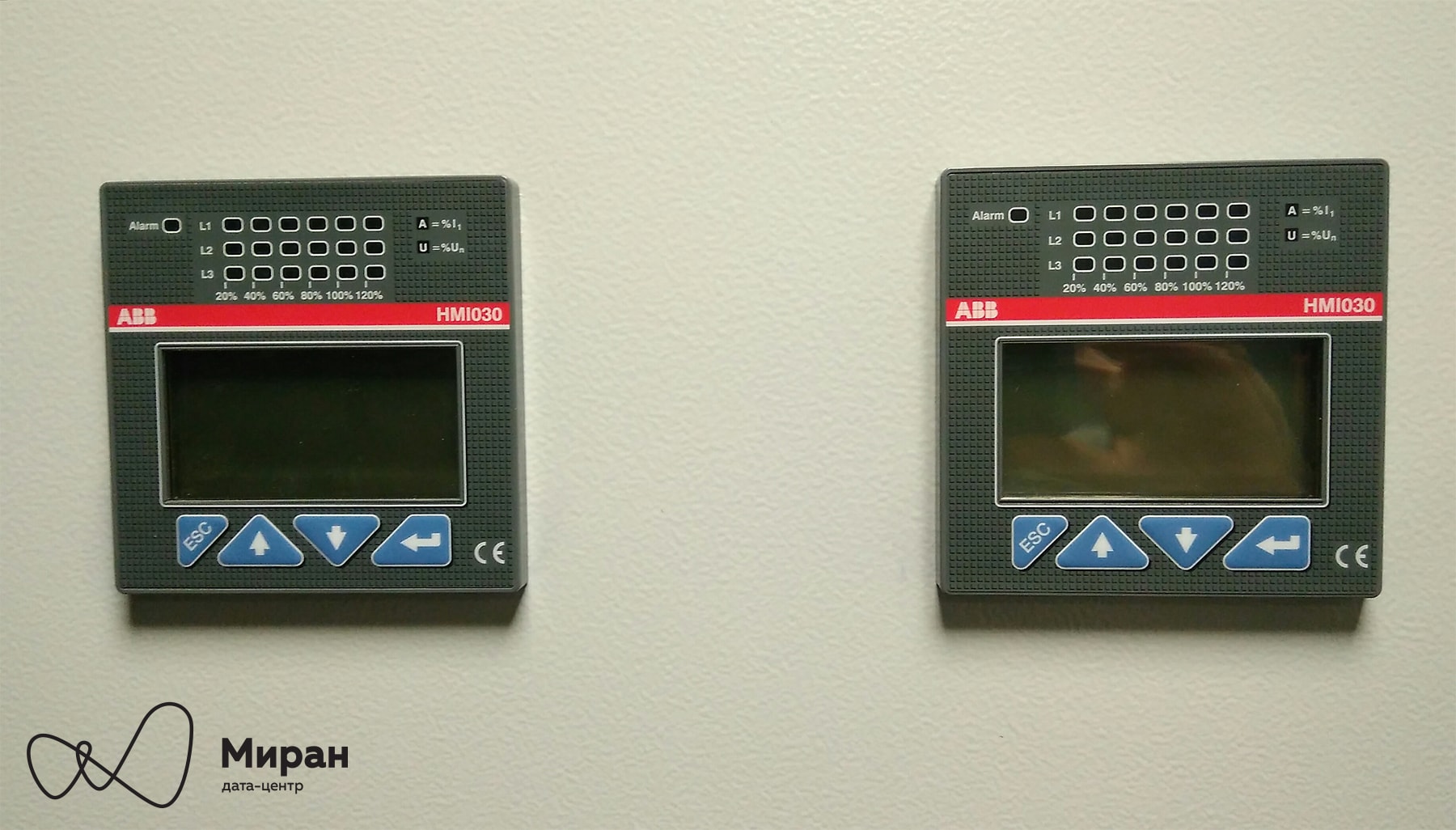
- backup. Normally, the third and fourth machines will be open and locked with padlocks. HMI 030 panels . ASU-3.1. Clickable Everything is clear here, human- machine sockets for issuing all kinds of statistics.
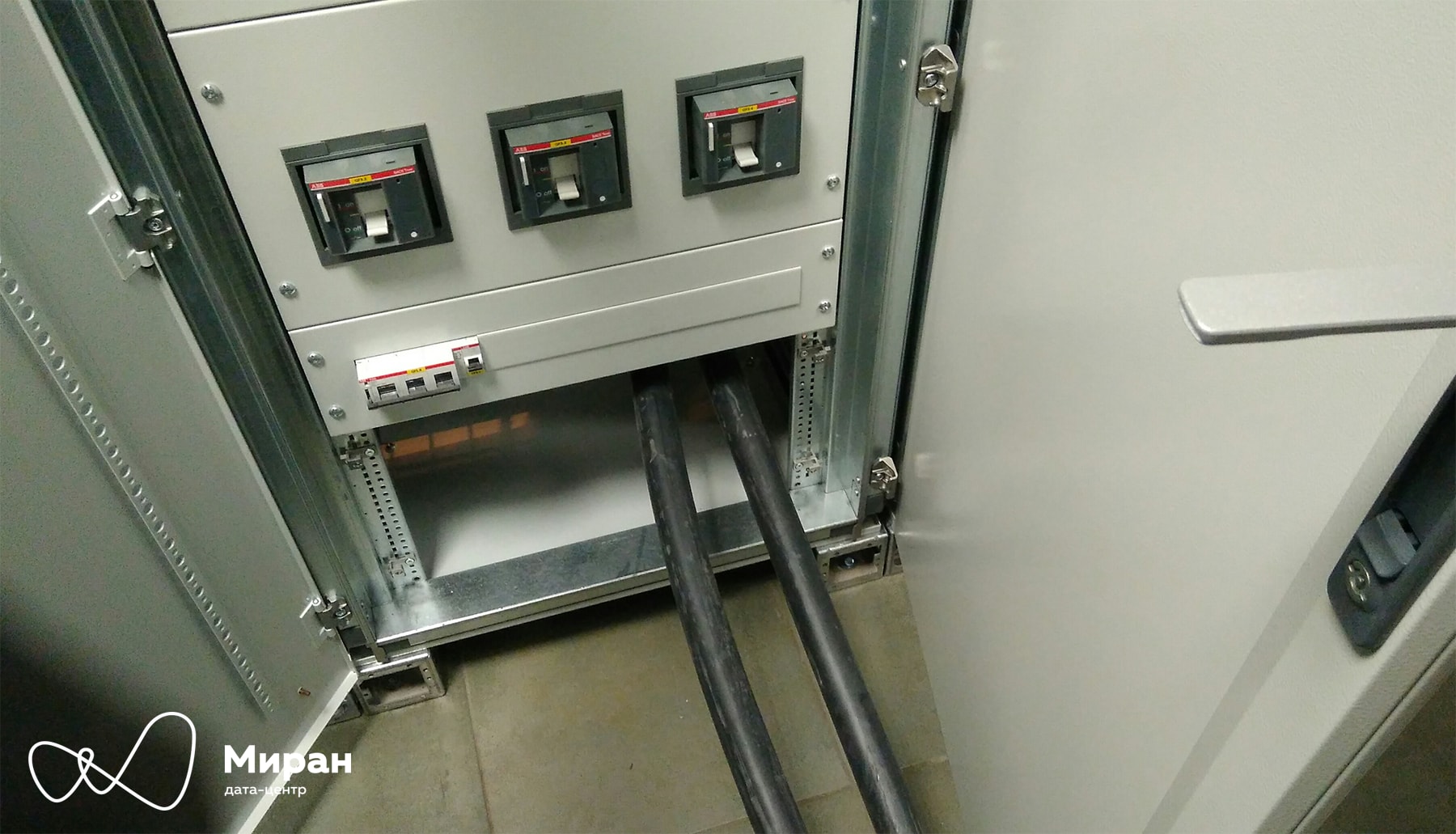

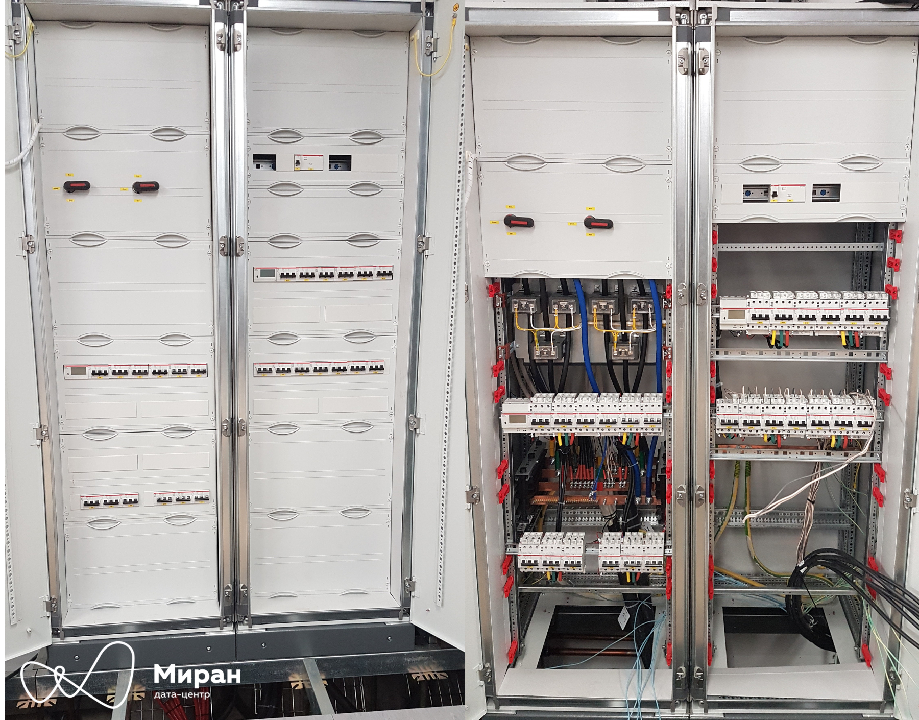
A bit of the insides of section No. 3 of VRU-3.1. Plastrons are still traveling, hmm ... Clickable
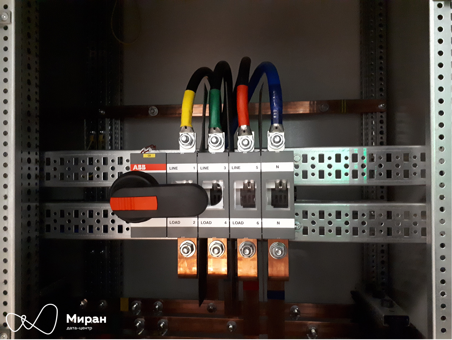
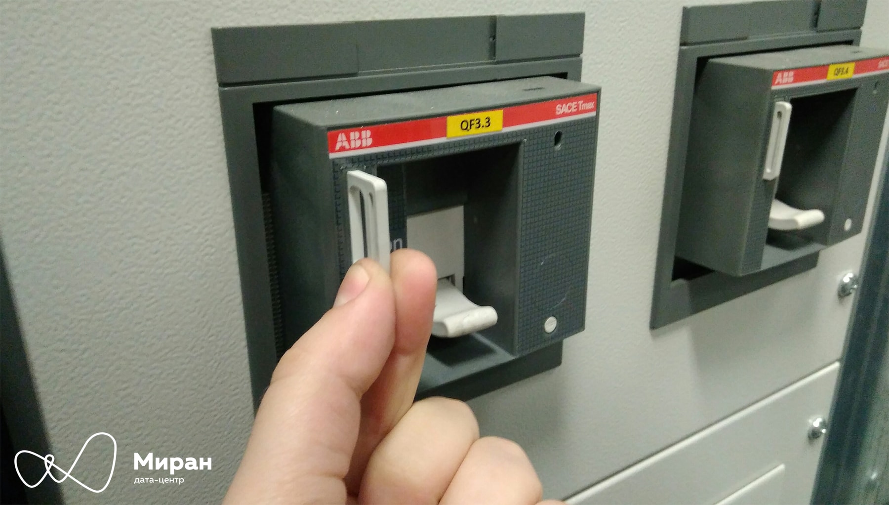
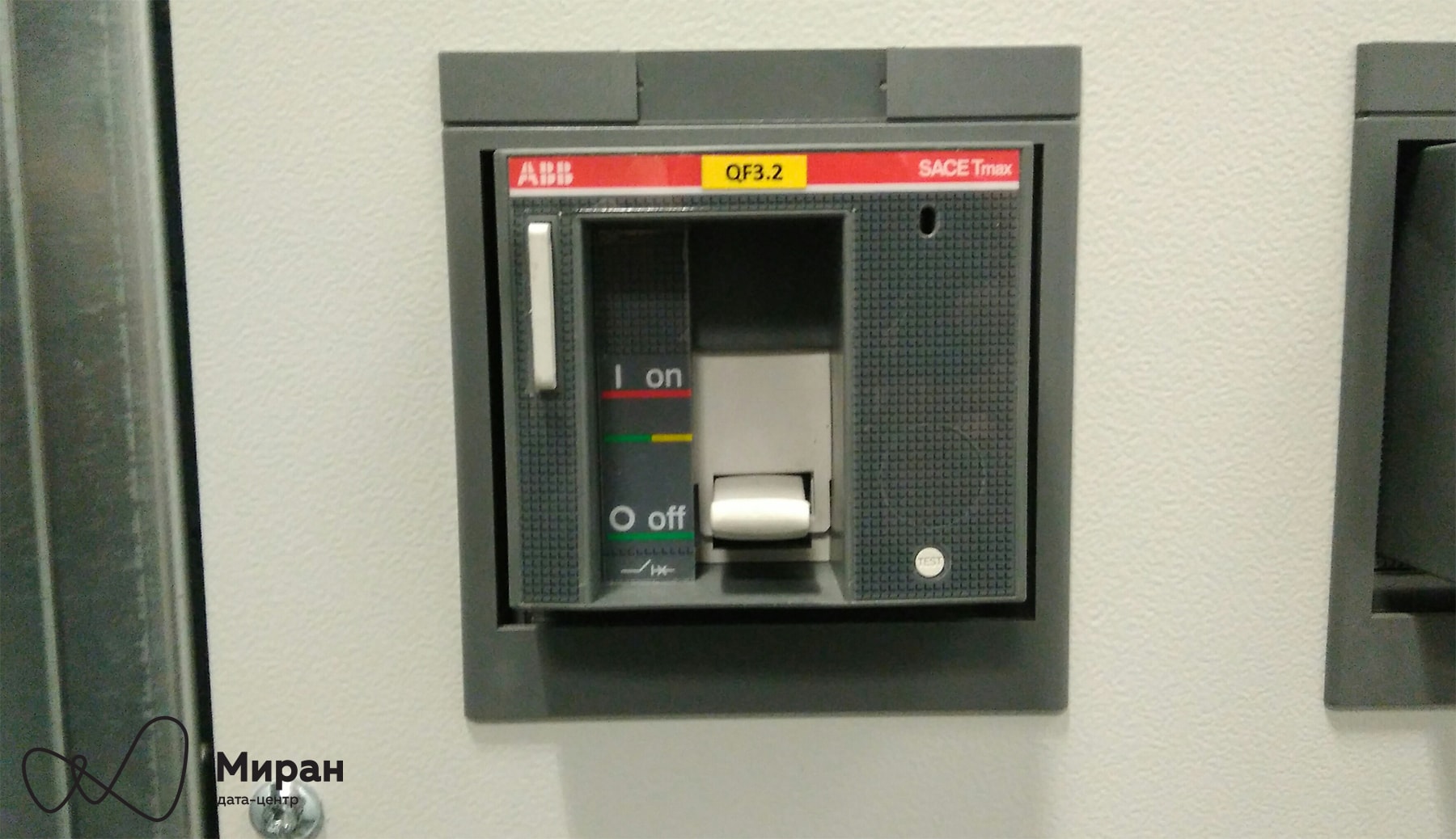
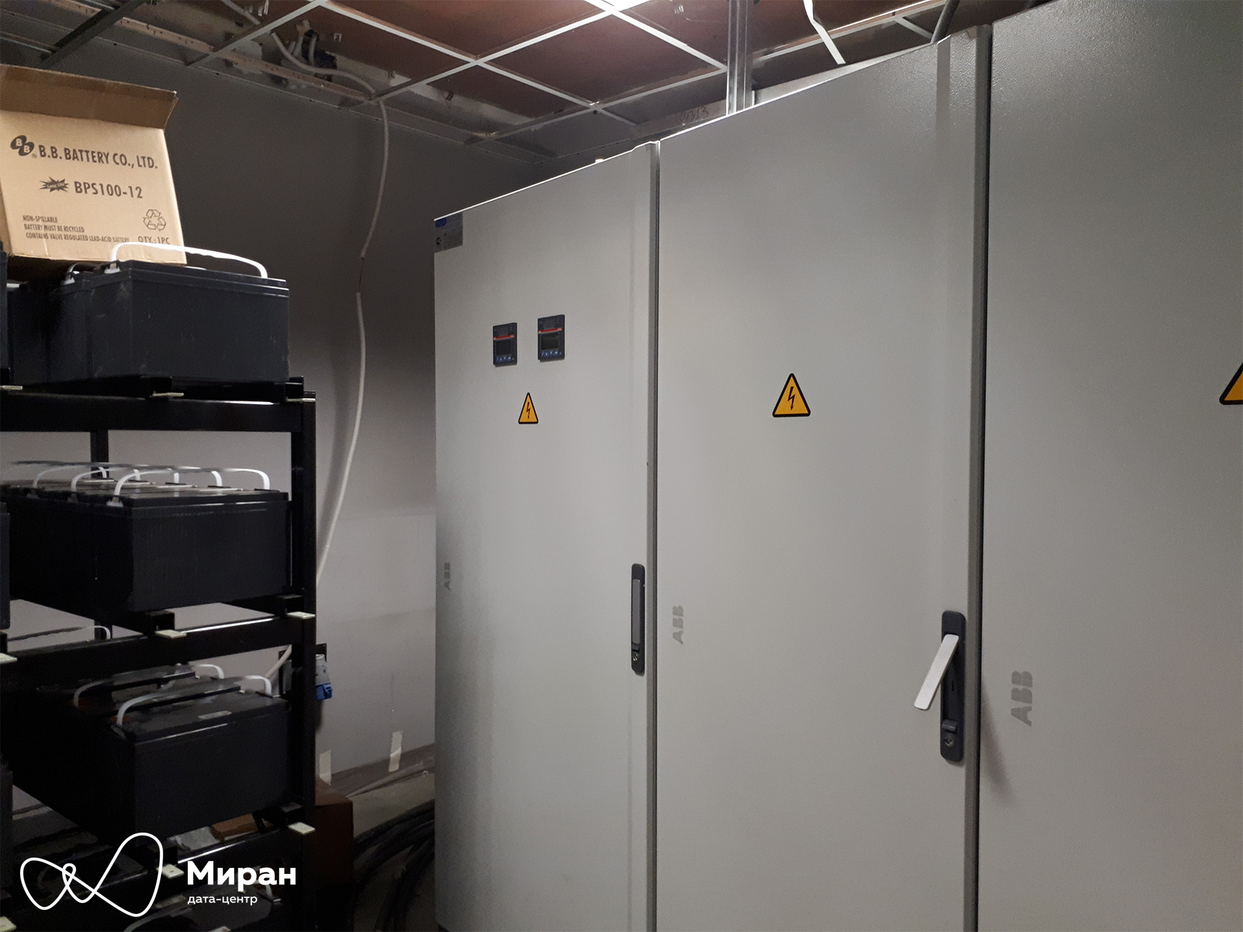
As you can see from the photos, we have implemented in these shields a single section No. 3 with two QS OETL 315 circuit breakers from the output of the UPS-1 and from the automatic machine QF1.3 of section No. 1. Six circuit breakers QF3.2- 3.7 Tmax T4N rated at 250 A provide power to the switchboard. From left to right: the first and fourth - to ShchR-1 and ShchR-2, the fifth and sixth - to ShchR-3 and ShchR-4, the second and third - reserve. Staples for padlocks. Optional Tmax T4N machines with front FLD flanges . ASU-3.1. Clickable Appearance of the switchgear and the associated UPS-1 batteries. Clickable
They are a little "combed and washed." Clickable
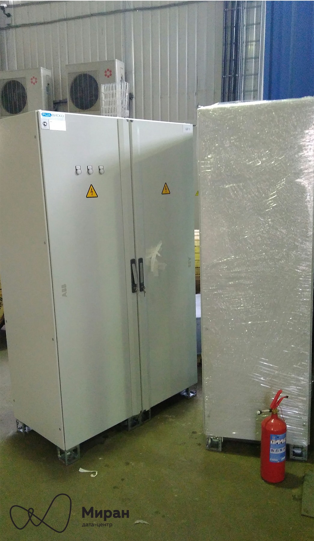
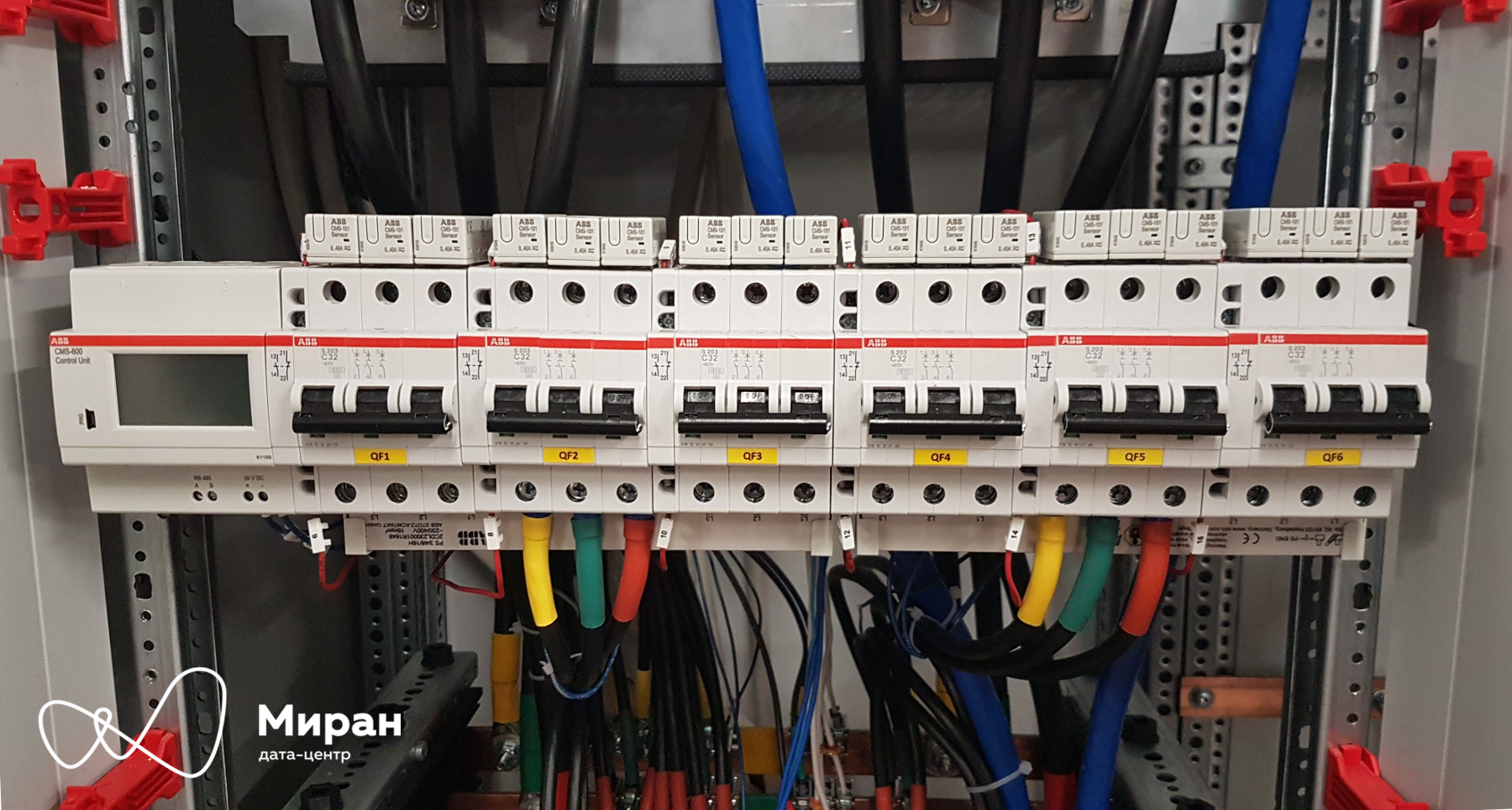
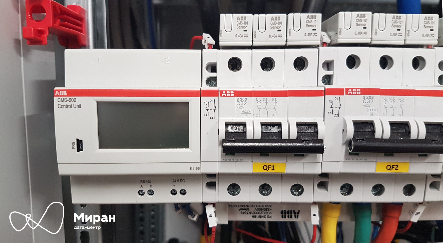
ЩР-1/2 Module №3 and fire extinguisher. Clickable Planted on the site ЩР-1. STULZ conditioner pretends to be “Malevich’s trapeze”. Clickable ShchR-2. Clickable The most important thing in shields. CMS 600 with current transformers. Clickable A little larger. Clickable These measurement systems came to our liking. It’s easy to set up, it’s easy to organize data acquisition. It is easy and simple to loop the current transformers in a loop, set their spatial placement on the measured machine, the order in the loop.

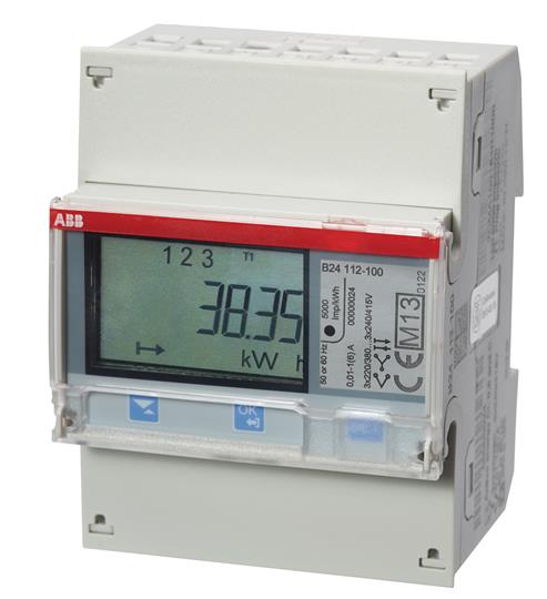
And this is also important. B24 counters . Those who still cannot reach us in any way. Photos from the ABB website. The
meters will provide us with voltage data for the supply lines. This data, as well as the measured current data from the CMS, will help us calculate the power consumed by the racks. Accordingly, monitoring of this capacity will allow us to understand whether the client exceeds the quota allowed to him.
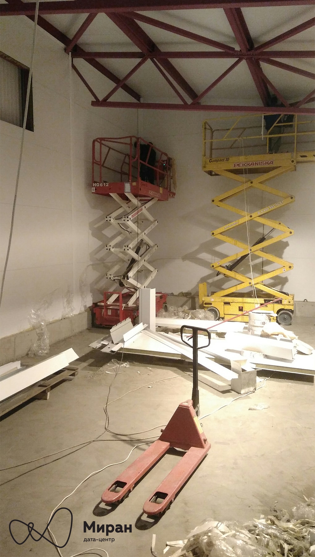
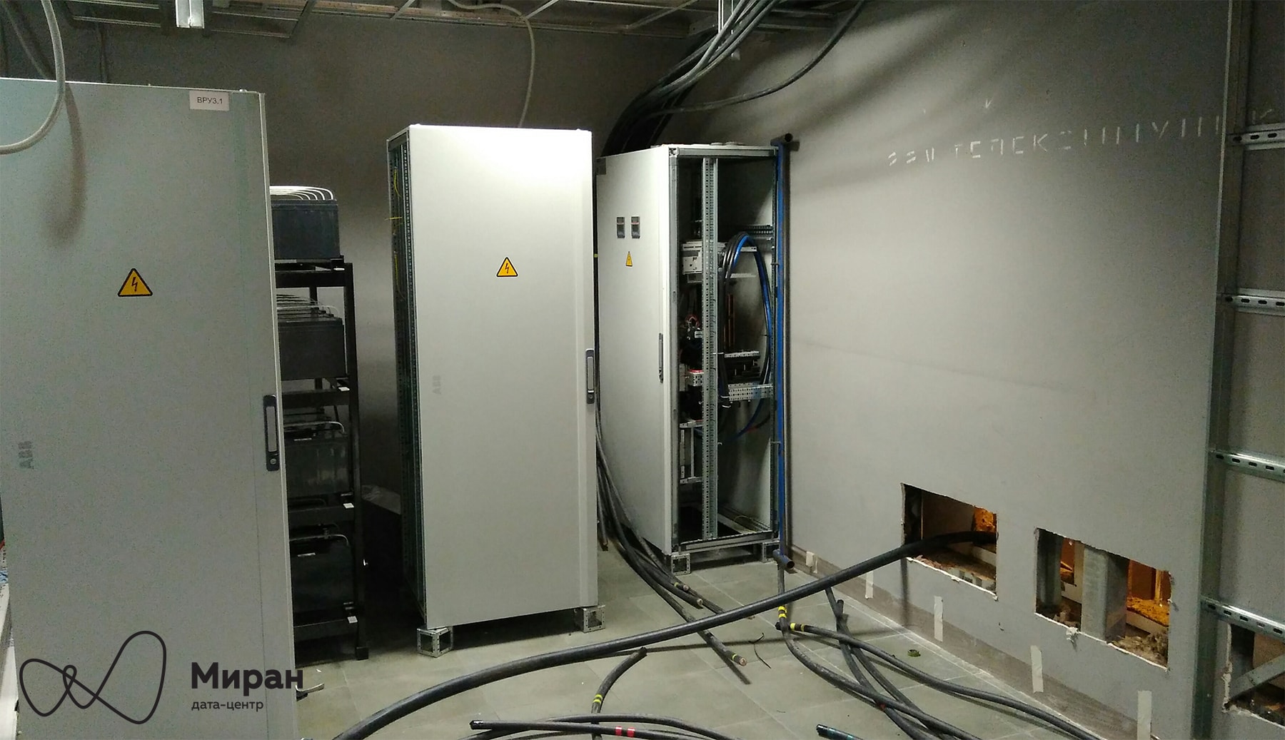
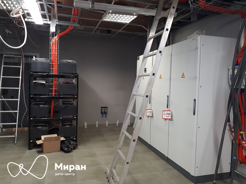
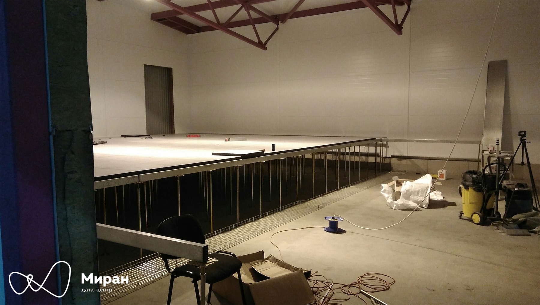
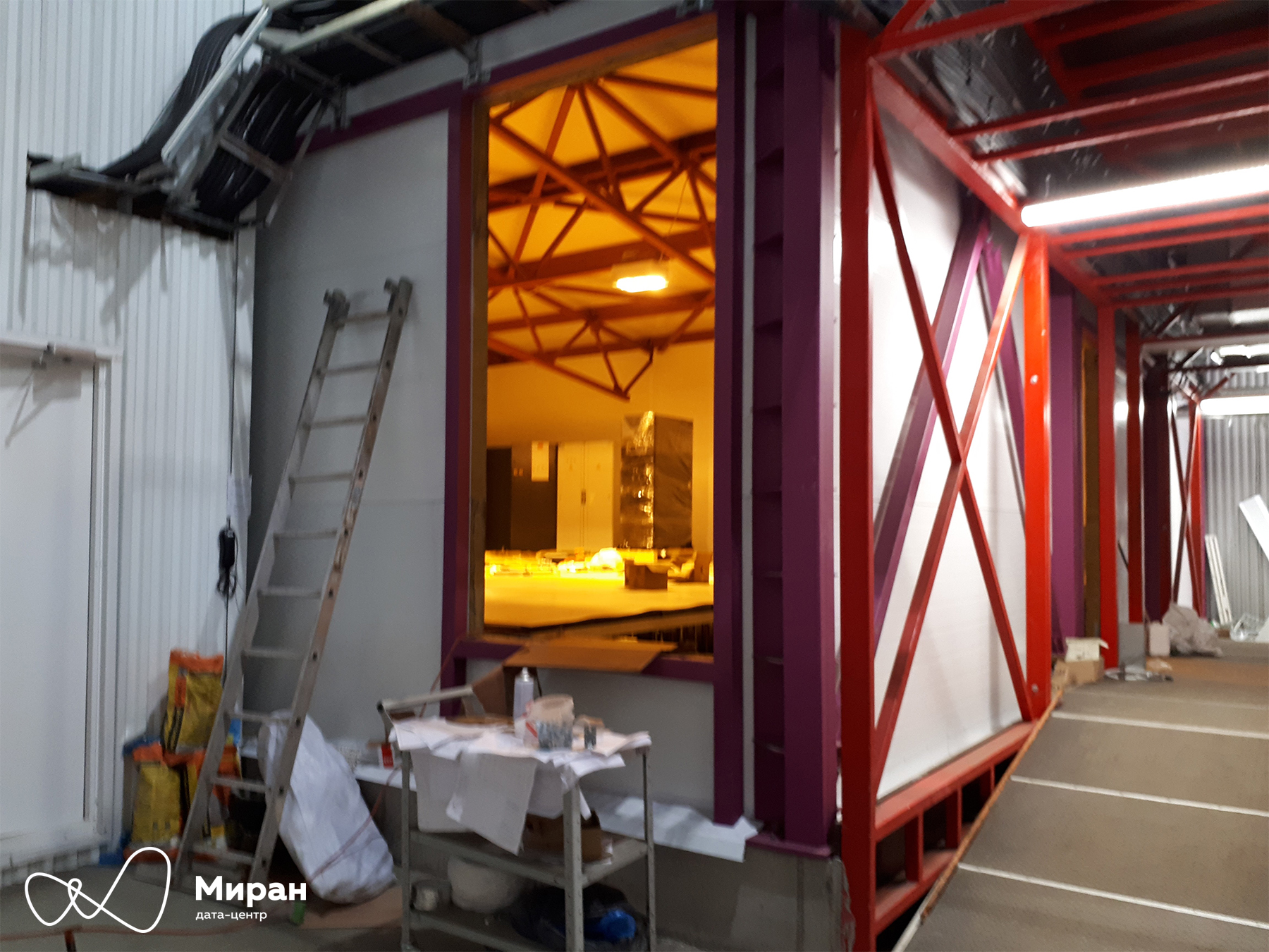
Installation of wall panels. Clickable Raised floor installation. Clickable There will be loading gates with a lift. In the background, the air conditioner STULZ, ЩР-2 and UPS-1 DELTA are posing. Clickable
To be continued.
Let's start with a report on the installation of ASUs and consumer shields.
Achtung! A lot of
I humbly ask you to forgive me for a number of vertical photographs.
1. ASU-3.1. Section No. 1
2. VRU-3.1. Section No. 3
3. ЩР-1/2
4. Current construction progress
ASU-3.1. Section No. 1
In Module 3, this time, we use fully solutions from ABB .
In Module No. 1 and Module No. 2, there were shields with filling from Schneider Electric . Newly arrived sections of the shield VRU-3.1 for Module No. 3. Clickable So far, we have acquired one of the two planned ASUs . The main idea of having two ASUs is redundancy and the possibility of various switching in switchboards without interrupting the power supply to consumers. General view of section No. 1 of VRU-3.1, as well as a view without plastrons. Clickable Two circuit breakers with a rating of 400 A - both under the control of ATS. Separately, it is worth noting that inside the shield itself there is no division of the section into two parts and no sectional switch between them, as was implemented in the ASU of the first two MCODs. Introductory machine
Tmax T5 in withdrawable version. Gearmotor MOE-E . Castle. ASU-3.1. Clickable Electronic release of the introductory machine PR223DS . Clickable In addition to traditional protection, the trip units measure current. These data, as well as data on the state of the machine via Modbus-RTU, will be transmitted to the dispatch system. Bracket for padlocks. Introductory machine. ASU-3.1. Clickable Manual spring loading . Introductory machine. ASU-3.1. Clickable ABP ATS 022 . ASU-3.1. Clickable
And here is ABP3.1. This is the first time we encounter this iron in the data center, unlike automatic machines. ATS is quite smart, plus it itself measures the voltage and related parameters on the main input buses. Based on whether there is voltage or not, the ATS will make a decision on the closing / opening of the machines. Measured data on Modbus-RTU will also go to the dispatch system. Automatic Tmax T4N , nominal 250 A. Cables are mounted. Clickable The main purpose of the QF1.1-1.2 machines is to provide power to the main and baypass inputs of the UPS-1. The QF1.3 machine feeds section No. 3 through the second QS switch . Machine QF1.4
- backup. Normally, the third and fourth machines will be open and locked with padlocks. HMI 030 panels . ASU-3.1. Clickable Everything is clear here, human- machine sockets for issuing all kinds of statistics.
ASU-3.1. Section No. 3
A bit of the insides of section No. 3 of VRU-3.1. Plastrons are still traveling, hmm ... Clickable
As you can see from the photos, we have implemented in these shields a single section No. 3 with two QS OETL 315 circuit breakers from the output of the UPS-1 and from the automatic machine QF1.3 of section No. 1. Six circuit breakers QF3.2- 3.7 Tmax T4N rated at 250 A provide power to the switchboard. From left to right: the first and fourth - to ShchR-1 and ShchR-2, the fifth and sixth - to ShchR-3 and ShchR-4, the second and third - reserve. Staples for padlocks. Optional Tmax T4N machines with front FLD flanges . ASU-3.1. Clickable Appearance of the switchgear and the associated UPS-1 batteries. Clickable
They are a little "combed and washed." Clickable
The input full power of the ASU is 200 kVA. Total 400 kVA per Module No. 3.
ЩР-1/2
ЩР-1/2 Module №3 and fire extinguisher. Clickable Planted on the site ЩР-1. STULZ conditioner pretends to be “Malevich’s trapeze”. Clickable ShchR-2. Clickable The most important thing in shields. CMS 600 with current transformers. Clickable A little larger. Clickable These measurement systems came to our liking. It’s easy to set up, it’s easy to organize data acquisition. It is easy and simple to loop the current transformers in a loop, set their spatial placement on the measured machine, the order in the loop.
Fun fact: taking into account the future purchase of ЩР-3/4, we will have the largest number of CMS 600 current measurement systems installed in Russia.
And this is also important. B24 counters . Those who still cannot reach us in any way. Photos from the ABB website. The
meters will provide us with voltage data for the supply lines. This data, as well as the measured current data from the CMS, will help us calculate the power consumed by the racks. Accordingly, monitoring of this capacity will allow us to understand whether the client exceeds the quota allowed to him.
The machine room of Module No. 3 is designed for the installation of 50 racks.
Estimated power consumption per section - 150 kVA. Accordingly, in total Module No. 3 is designed for 300 kVA of consumption.
Construction progress on 10/03/2017 - 10/09/2017
Installation of wall panels. Clickable Raised floor installation. Clickable There will be loading gates with a lift. In the background, the air conditioner STULZ, ЩР-2 and UPS-1 DELTA are posing. Clickable
PS Features of national business ...
- Guys, we paid you the raised floor tiles and their delivery n-days ago, where are they?
- Oh, and we sold them to another client already ...
- Guys, according to the documents you delivered the whole profile to us, in fact, there is still a fifth part, where is the profile?
- Oh ...
To be continued.