Homemade plotter: tips for beginners, working with grbl-firmware
While studying at the university such an interesting subject as circuitry, it occurred to me to do as part of the course project "Two-Axis Plotter on Paper with a Head from an Arduino Pen". By the time I started work, I had a very vague idea of the development of the electrical part of the project, as well as the mechanical part. This experience in my life has not happened. That is why I found in the network, sorting through many resources, which seemed to me the most simple and understandable tutorial, and decided to follow it exactly. However, it soon became clear that everything simple at first glance is not detailed enough for such a "craftsman" as me. Therefore, in the remaining "off-screen" issues had to improvise, not always successfully, as it turned out later. It was a little backstory. Now I would like to share my valuable experience on a number of key issues. I will not give a completely new instruction with my version of this device, since on the Internet so much more successful solutions.
Content
1. Construction
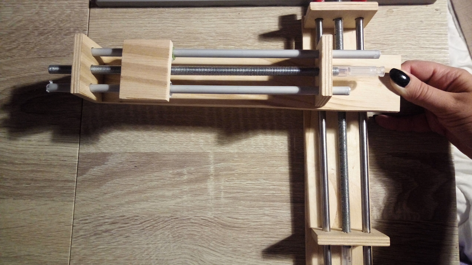
The design I chose was made of plywood. Studs were used as axles, which were turned by stepper motors, and due to this, the platform on the nuts moved along the axis. One axis was attached to the platform with another one edge. From the manufacture of all this I can say:
- If the upper axis does not have support on both sides, and is attached, like mine, with only one edge, then it is necessary to think in advance about the balance of the axes. The upper one will inevitably tilt, if at all not to overwhelm the entire structure with the weight of its “hanging” edge.
- The lines of the pattern can go in waves according to the size of the thread of the stud, as well as due to the shaking of the structure itself during operation.
- The above two problems lead to one more thing: the pen (in my case, the pen) can write unevenly in different parts of the page.
- The weight and dimensions of the device should also be calculated in advance, so that later it does not become clear that your engines do not pull such a load.
- And one more important detail: it is best to use screws, nails, etc., wherever possible, for fastening. Constructions on glue, even the most reliable, tend to fall apart at the most unexpected moment. And in some cases, after assembling the main part, it will be very difficult to return to the "glueing" of small, but very important, internal parts, without disassembling the finished parts.
- If you use glue somewhere, then be very, very careful that it does not get into the moving parts of the structure. Even a small droplet can stop the mechanism and make it worthless.
2. Electric circuit

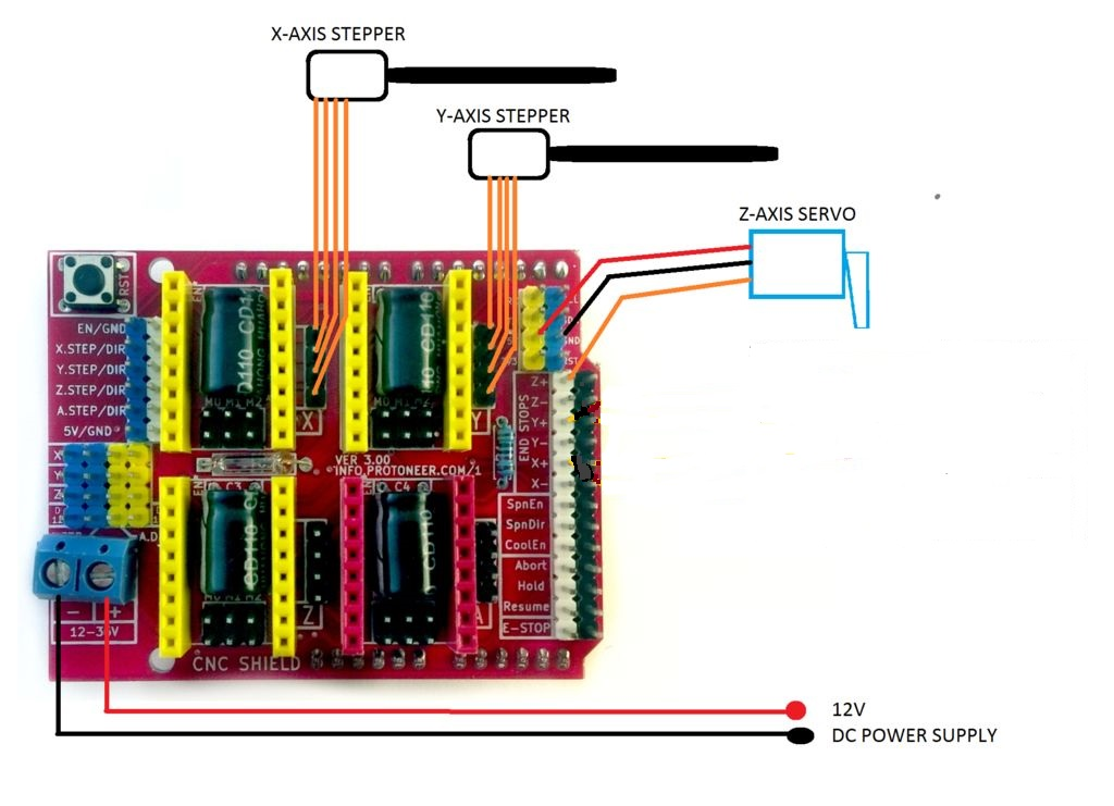
The scheme itself was extremely simple and did not even require soldering. I even took a ready-made CNC Shield specifically for working with CNC. Nevertheless, there are some nuances here:
- My Chinese analogue of the Arduino, codenamed WAVGAT, refused to flash as a regular Arduino Uno R3. On the Internet, they said that such boards are fully compatible with all arduino software, but to work with it through IDE, they had to download a separate WAVGAT Update library. So I managed to upload a sketch to the board, but the software itself still did not want to work correctly. I tried all the fixes found for this kind of problem (I overloaded the bootloader, changed the boards files and constants of the software library itself), but the result remained the same. Apparently, for this task it is necessary to acquire the classic Arduino.
- Another problem was the launch of stepper motors. They buzzed, basked, despite the cold drivers, but did not move. Methodically checking the chain element by element realized that the problem is in their connection. The fact is that this time the Chinese were originating. It turned out that the engine leads contain crossed AB pairs. If a pair of ordinary shop motors went in order 2B-2A-1A-1B, then for some reason, the Chinese had 2B-1A-2A-1B. You can figure this out by “picking up” the circuit with a multimeter in the appropriate mode: pair AB-s outputs are squeaking.
- And yet, as it turned out, a harmless low-power servo is quite capable of irrevocably “burning up” the entire arduino board during prolonged excessive load on it. In this case, the board will continue to work, but will sometimes be interrupted in the middle, stopping at servo commands.
- Therefore, monitor the temperature of devices during operation in order to avoid irreparable consequences.
3. software
There are options:
- The easiest way to take a great unpretentious program BenVox. It is specialized specifically for work with CNC and is easy to install and handle. Minus this option in its limitations. Firstly, the firmware for the board in the software bundle is already contained in the hex-file, because there are problems with editing it. And the functionality in general is not very extensive, similar to the simplest graphics editor. If you do not want to go into the details of the work of this whole mechanism, then you can work with this option.
- A little harder, but also more promising work through the GRBL firmware. This library can be easily taken on the Internet and it provides much more features than BenBox. But to work through this mechanism, you need to understand the initial configuration of all this.
- So, download and unpack the grbl-servo library. Now it can be poured onto the board through the IDE, simply by finding it among the examples.
- To send commands directly to the device, you need a Universal Gcode Sender (or other similar software). After it is installed on the computer in it, we open a communication channel with the board on the com port to which the board is connected.
- For the initial and subsequent settings of the board, in the application command line type "$$". With this command, we get a complete set of basic settings for the board, which can be changed by setting the necessary parameters. For example, the commands "$ 110 = 380" and "$ 111 = 380" set the speed of the engines on the X and U axes to 380 mm / min. Important settings are the speed and acceleration of the engines, the direction of the axes (direct or inverse). More instructions for such a setting can be found on the Internet.
- There is also the possibility of engine control over the engines (machine control tab) and servo (M5 commands (turn to the starting position) and M3 s90 (turn 90 or any other number of degrees)).
- Next you need to prepare an image for work. For this, too, need extra. Software, for example, Inkscape. It looks like any other graphic editor and you can study it in detail in the Internet. But there are a couple of important points:
- First you need to set the correct page size in the properties so that the size of your image does not turn out to be more than a plotter. It is also necessary to replace pixels by millimeters in units of measurement.
- After creating the image, press ctrl + shift + C and go to the menu - extensions - MI GRBL ... - set the speed of the engines and the angle of rotation of the servo - save the image in gcode format.
- Finally, we return to the Universal Gcode Sender and in the File Mode tab open our gcode image. Using the Visualize button, you can graphically monitor the operation of the program, and in the command table you can follow the command execution. It remains only to run all this and observe the result.
As a result, the work on such a device turned out to be difficult and laborious, and the end result is not ideal. But this experience is interesting and not useless. Therefore, I hope someone will come in handy and help to avoid unnecessary "rakes" my advice.