Alcatel Lucent Service Router as a gateway for an access domain
For many, the first acquaintance with Alcatel Lucent (now Nokia) service routers is not very pleasant due to the particular vendor’s service model. Unlike Cisco equipment, it is not always obvious how to make such a device work in a simple scenario: a router for multiple access switches (usually such switches are connected in a ring). Those who are disappointed without discovering the spanning-tree command in configuration mode are dedicated.
Imagine a simple topology:
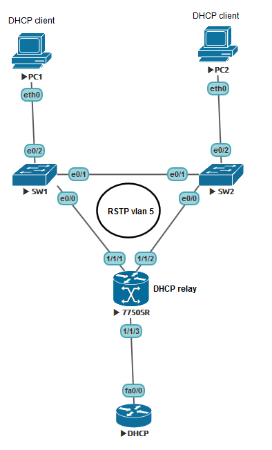
Two access switches connected in a ring with a router, a device with TimOS on board (in this case, the SR7750 emulator) and an external DHCP server that serves several IP networks. In this situation, the 7750 has several alter ego:
1) Default gateway. PC1 and PC2 quite naturally want to communicate with external networks, so you need to provide them with an IP address where you can send all objectionable packets.
2) DHCP realy. Since the discover message is sent by the broadcast, it must be sent to the external Unicast server as a message.
3) RSTP root bridge. It is hardly rational to enable an access switch to become a root.
Immediately make a reservation that the SR7750 is a router. It is not intended for switching traffic between two interfaces, it does not support SVI in a classic form with all the consequences. To use the device in such a topology, it is necessary to create an improvised and very simple VPLS (although, of course, in the case of two interfaces, a pseudowire would also work). To configure VPLS in our case, it is absolutely not necessary to understand the principles of MPLS.
So let's get started.
0. Our preliminary step is to configure the user. VPLS from the point of view of SR is a service, and any service should belong to the user.
1. Configure the 1/1/1 and 1/1/2 interfaces.
After this, the command
2. Configure the VPLS service.
SAP (Service Access Point) is an attachment circuit in a slightly more well-known terminology. The point to which the subscriber device is connected. In our case, an access switch. The number after the colon is the vlan number.
This is where we include STP. By default, the operating mode is RSTP, and our SAPs will be point-to-point interfaces in terms of STP. We set Priority 4096 with the intent to turn our pseudo-switch into a root bridge.
Basic check can be done with
3. So, the interface.
As you can see, here we killed two birds with one stone: we configured the default gateway and provided DHCP Relay to the clients. Note that IES and VPLS are different services with different id.
Verify that the UP interface can be
4. Configure the interface towards the kernel, where the DHCP server is located. For simplicity, we will connect to the server by a static route. Do not forget about the value of MTU from the kernel.
Turn on the interface:
Configure the IP part:
The routing table can be viewed using
At this simple, but slightly unusual setup Alcatel completed. At first glance, VRRP is not enough, but in order to enable VRRP, you need to add an MPLS interface between the two routers. In addition to SAP, SDPs will be added to our VPLS. But this is a completely different story.
Software Version: TiMOS-B-12.0.R6.
Image and console: UNL
Thank you for your attention.
Imagine a simple topology:
Two access switches connected in a ring with a router, a device with TimOS on board (in this case, the SR7750 emulator) and an external DHCP server that serves several IP networks. In this situation, the 7750 has several alter ego:
1) Default gateway. PC1 and PC2 quite naturally want to communicate with external networks, so you need to provide them with an IP address where you can send all objectionable packets.
2) DHCP realy. Since the discover message is sent by the broadcast, it must be sent to the external Unicast server as a message.
3) RSTP root bridge. It is hardly rational to enable an access switch to become a root.
Immediately make a reservation that the SR7750 is a router. It is not intended for switching traffic between two interfaces, it does not support SVI in a classic form with all the consequences. To use the device in such a topology, it is necessary to create an improvised and very simple VPLS (although, of course, in the case of two interfaces, a pseudowire would also work). To configure VPLS in our case, it is absolutely not necessary to understand the principles of MPLS.
So let's get started.
Remember to configure the card in the emulator.
If you do not use the emulator, the types of cards and modules can be determined with simple commands:
card 1
        card-type iom3-xp-b
        mda 1
            mda-type m5-1gb-sfp-b
            no shutdown
        exit
        no shutdown
If you do not use the emulator, the types of cards and modules can be determined with simple commands:
show card
show mda
0. Our preliminary step is to configure the user. VPLS from the point of view of SR is a service, and any service should belong to the user.
        customer 5 create
            description "Access ring 1"
        exit
1. Configure the 1/1/1 and 1/1/2 interfaces.
    port 1/1/1
        ethernet
            mode access
            encap-type dot1q
        exit
        no shutdown
    exit
    port 1/1/2
        ethernet
            mode access
            encap-type dot1q
        exit
        no shutdown
    exit
After this, the command
show portcan verify that the settings are correct. Note that the MTU has become 1518 = 1500 for IP + 14 Ethernet + 4 dot1q vlan. It is quite natural that when configuring QinQ, the device itself will determine the frame size at 1522.Spoiler
===============================================================================

Ports on Slot 1

===============================================================================

Port Admin Link Port Cfg Oper LAG/ Port Port Port C/QS/S/XFP/

Id State State MTU MTU Bndl Mode Encp Type MDIMDX

-------------------------------------------------------------------------------

1/1/1 Up Yes Up 1518 1518 - accs dotq xcme GIGE-LX 10KM

1/1/2 Up Yes Up 1518 1518 - accs dotq xcme GIGE-LX 10KM
2. Configure the VPLS service.
service
 vpls 5 customer 5 create
            allow-ip-int-binding
            stp
                priority 4096
                no shutdown
            exit
            service-name "Access-ring-1"
            sap 1/1/1:5 create
            exit
            sap 1/1/2:5 create
            exit
            no shutdown
        exit
    exit
SAP (Service Access Point) is an attachment circuit in a slightly more well-known terminology. The point to which the subscriber device is connected. In our case, an access switch. The number after the colon is the vlan number.
This is where we include STP. By default, the operating mode is RSTP, and our SAPs will be point-to-point interfaces in terms of STP. We set Priority 4096 with the intent to turn our pseudo-switch into a root bridge.
allow-ip-int-bindingnecessary in order to allow you to bind the IP interface (read SVI) to our VPLS. This interface will be bound using the name of our service. Basic check can be done with
show service id 5 baseSpoiler
===============================================================================

Service Basic Information

===============================================================================

Service Id : 5 Vpn Id : 0

Service Type : VPLS

Name : Access-ring-1

Description : (Not Specified)

Customer Id : 5 Creation Origin : manual

Last Status Change: 12/06/2016 21:37:01

Last Mgmt Change : 12/06/2016 21:37:01

Etree Mode : Disabled

Admin State : Up Oper State : Up

MTU : 1514 Def. Mesh VC Id : 5

SAP Count : 2 SDP Bind Count : 0

Snd Flush on Fail : Disabled Host Conn Verify : Disabled

Propagate MacFlush: Disabled Per Svc Hashing : Disabled

Allow IP Intf Bind: Enabled

Def. Gateway IP : None

Def. Gateway MAC : None

Temp Flood Time : Disabled Temp Flood : Inactive

Temp Flood Chg Cnt: 0

VSD Domain : none


-------------------------------------------------------------------------------

Service Access & Destination Points

-------------------------------------------------------------------------------

Identifier Type AdmMTU OprMTU Adm Opr

-------------------------------------------------------------------------------

sap:1/1/1:5 q-tag 1518 1518 Up Up

sap:1/1/2:5 q-tag 1518 1518 Up Up

===============================================================================
3. So, the interface.
service
 ies 15 customer 5 create
            interface "DGW-1" create
                address 10.0.0.6/29
                dhcp
                    server 10.10.10.10
                    relay-unicast-msg
                    no shutdown
                exit
                vpls "Access-ring-1"
                exit
            exit
            no shutdown
        exit
As you can see, here we killed two birds with one stone: we configured the default gateway and provided DHCP Relay to the clients. Note that IES and VPLS are different services with different id.
Verify that the UP interface can be
show service id 15 interfaceSpoiler
===============================================================================

Interface Table

===============================================================================

Interface-Name Adm Opr(v4/v6) Type Port/SapId

 IP-Address PfxState

-------------------------------------------------------------------------------

DGW-1 Up Up/-- IES rvpls

 10.0.0.6/29 n/a

-------------------------------------------------------------------------------

Interfaces : 1

===============================================================================
4. Configure the interface towards the kernel, where the DHCP server is located. For simplicity, we will connect to the server by a static route. Do not forget about the value of MTU from the kernel.
Turn on the interface:
    port 1/1/3
        ethernet
        exit
        no shutdown
    exit
Configure the IP part:
router
        interface "To-CORE"
            address 172.16.0.0/31
            port 1/1/3
            no shutdown
        exit
        interface "system"
            no shutdown
        exit
        static-route 10.10.10.10/32 next-hop 172.16.0.1
The routing table can be viewed using
show router route-tableSpoiler
===============================================================================

Route Table (Router: Base)

===============================================================================

Dest Prefix[Flags] Type Proto Age Pref

 Next Hop[Interface Name] Metric

-------------------------------------------------------------------------------

10.0.0.0/29 Local Local 00h17m25s 0

 DGW-1 0

10.10.10.10/32 Remote Static 00h05m05s 5

 172.16.0.1 1

172.16.0.0/31 Local Local 00h05m05s 0

 To-CORE 0

-------------------------------------------------------------------------------

No. of Routes: 3

Flags: n = Number of times nexthop is repeated

 B = BGP backup route available

 L = LFA nexthop available

 S = Sticky ECMP requested

===============================================================================
At this simple, but slightly unusual setup Alcatel completed. At first glance, VRRP is not enough, but in order to enable VRRP, you need to add an MPLS interface between the two routers. In addition to SAP, SDPs will be added to our VPLS. But this is a completely different story.
Software Version: TiMOS-B-12.0.R6.
Image and console: UNL
Thank you for your attention.