Find out how to increase your WiFi coverage.
From time to time we all face the problem of an insufficient signal level of the router. The signal is unstable at some points, often disappears or not at all. This is noticeable in rooms with a large area: in the country, in a private house, in a recreation center, in an apartment in which there is more than one room. In this article, we describe solutions to this problem.
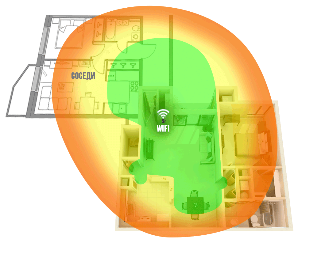
Figure 1. The WiFi coverage area of the router network in a typical apartment (router next to the front door).
We produce passive and active antennas, including for data networks, WiFi. In this article, we are not so much interested in wireless access issues as in ways to increase WiFi coverage. Note that we do not consider specific options for creating special “powerful” access points. Everything is only within the framework of standards and norms adopted in the Russian Federation.
In our experience, the router is usually placed: next to the front door, in the corridor behind the cabinet, or in the distribution panel. In such cases, the area of the apartment is not uniformly covered by the WiFi network. Depending on the layout of the apartment, the far rooms, the kitchen, the loggia are outside the zone of sustainable coverage. (Example in Figure 1)
The same situation is true for a private house. The area of the house is usually larger, and the Internet is needed not only indoors, but also outside - at the barbecue area, pool, on the playground. Here the problem is more serious.
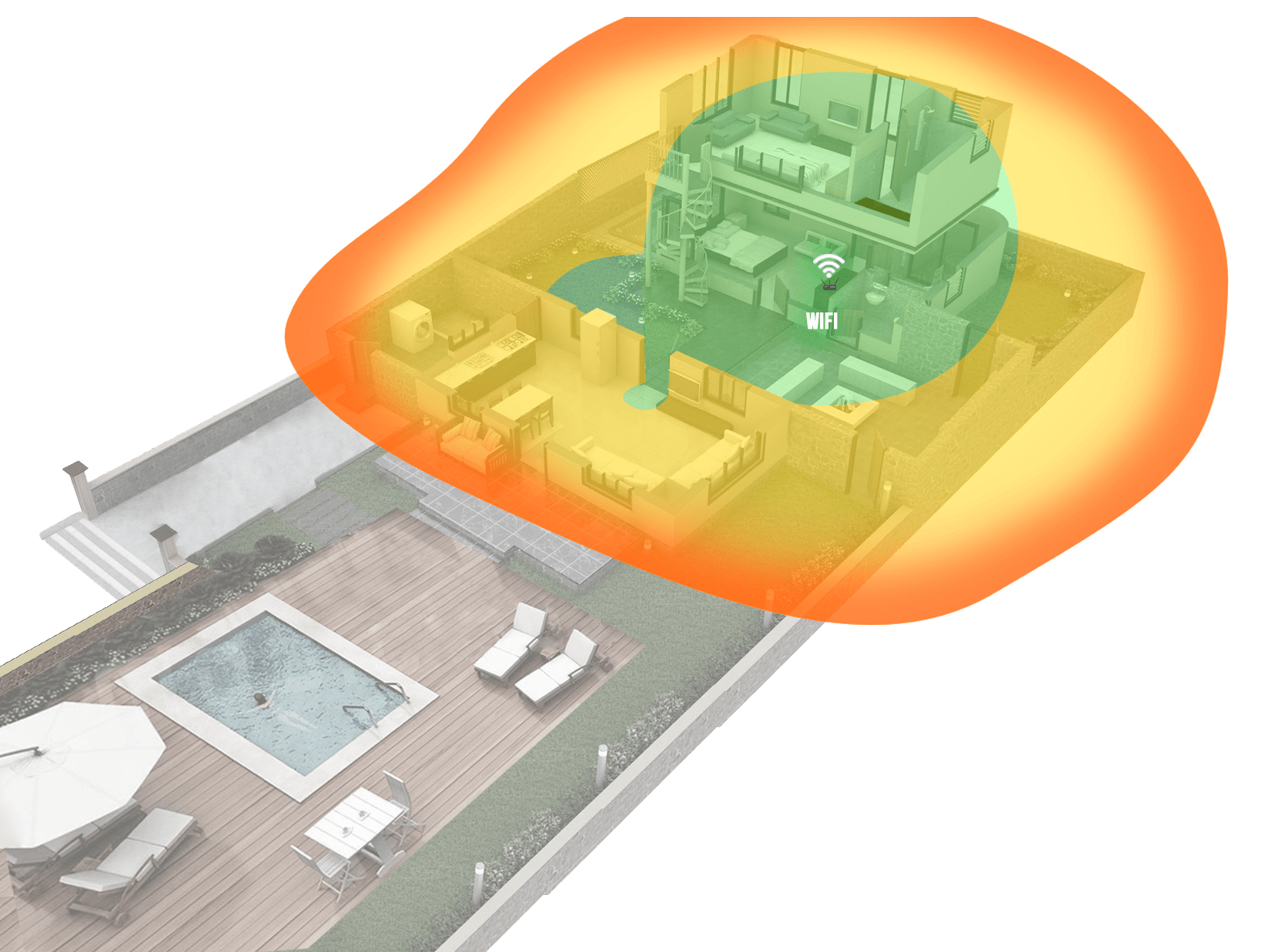
Figure 2. WiFi coverage area of the router network in a country house
Figures 1 and 2 show examples of WiFi coverage, green areas with a good network level are highlighted in green, red with a low level, which often does not allow you to work normally on the Internet. Note that the WiFi signal, being a radio wave, spreads better in free space, so the walls and other partitions in the room will weaken it and, as a result, reduce the level of the signal that passed through them.
The problem is identified - insufficient coverage of the WiFi network in the room. Let's see why this is happening. The router’s standard antenna has a circular radiation pattern - it radiates WiFi in all directions. Including towards your neighbors, which is usually pointless and not necessary. At the same time, the antenna’s own gain is relatively small, as a result of which, such an antenna has insufficient efficiency. As a result, the coverage area of the WiFi signal is small.
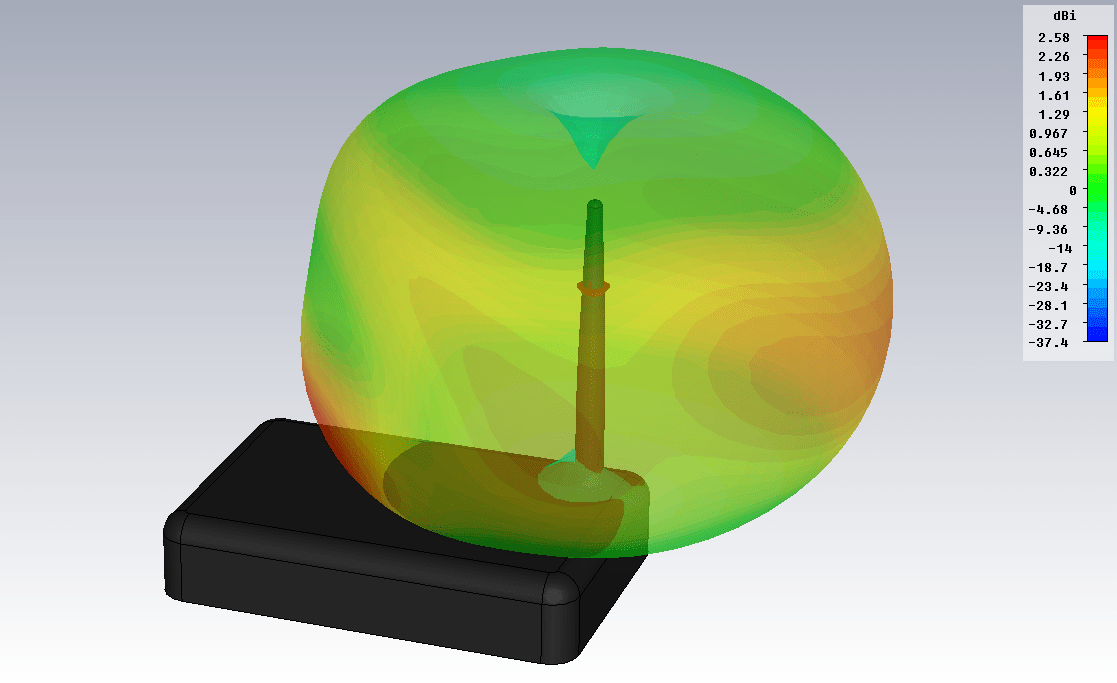
Figure 3. The radiation pattern of a standard router antenna (f = 2.45 GHz)
Figure 3 shows the radiation pattern of an external antenna of a standard router, calculated in a physical simulator. A dipole is used as an antenna.
The first thing that comes to mind is to replace the router with another one. Buy a device with a more powerful external antenna or with several antennas. If you have an outdated router model, then it's worth a try. Be prepared that this will require additional costs, and a positive result is not guaranteed at all. Most likely, the picture will improve, but the problem will not be resolved (Fig. 4-5).
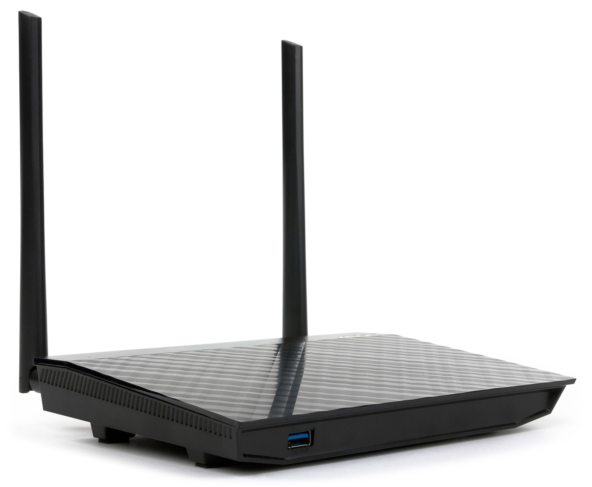
Figure 4. A router with two external antennas.
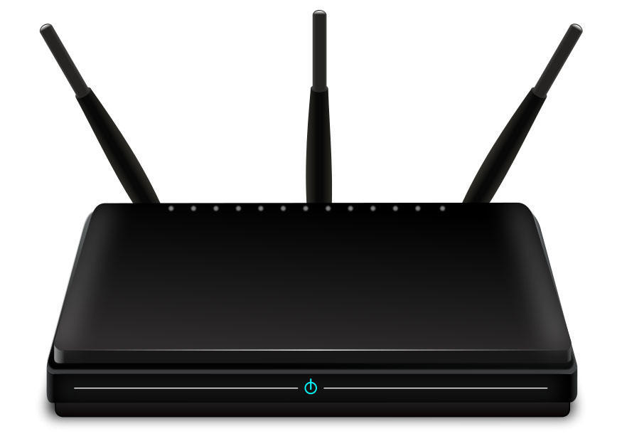
Figure 5. A router with three external antennas.
The next way is to use an active WiFi repeater, it is also called a WiFi repeater. This device is just designed to increase the range of a WiFi network. A great way, often allowing you to solve the problem in the bud. But he has also disadvantages:
- prices from one and a half thousand rubles and higher;
- the need for customization;
- limited area of use.
And this is not all: the repeater will again receive a signal from all sides and radiate around. That is, if we have an “unreached” corner of the apartment far, then two or even three repeaters will be required. It would be great to concentrate the signal in a given direction, but it won’t work out - the built-in repeater antennas have a pie chart. Repeaters with a jack for an external antenna we did not meet.
It is worth mentioning another feature of the WiFi repeater - the presence of 220V mains power. Not all people are ready to leave some devices connected to the network when leaving home. And turn on and off every time - an activity for an amateur. In addition, for a house or cottage, the decision is complicated by the fact that between the house and, say, a barbecue area, most often there is no power supply, and repeaters are often not designed for outdoor use.

Figure 6. Principle of operation of the WiFi repeater
The next solution is to use an external directional antenna. The simplest thing is to unscrew the standard antenna from the router and connect a directional one that will focus the entire signal in the desired direction. Antennas of this kind are numerous, but we will focus on the development of our enterprise.
The first solution is the WiFi Extender antenna (Figure 7):
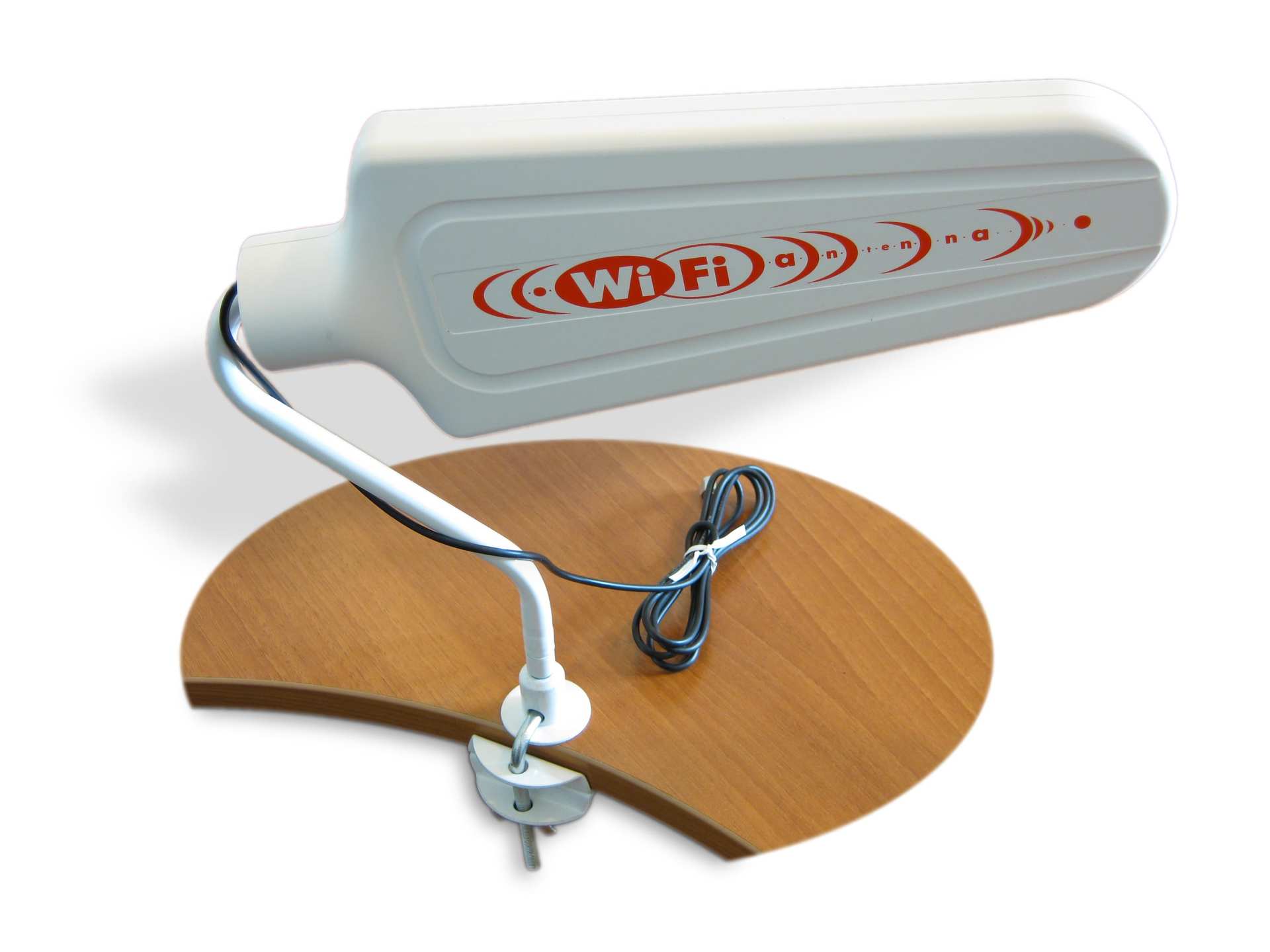
Figure 7. WiFi Extender Antenna
This is a wave channel indoor antenna in a transparent plastic case. Antenna gain 10 dBi.
The second option is more complex and effective - a panel antenna. In our case, BAS-2301 WiFi (Figures 8-9). Inside the radiotransparent sealed enclosure is a patch antenna. Gain of at least 12.5 dBi.
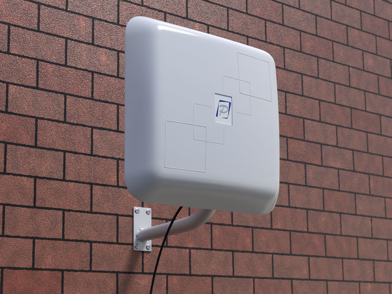
Figure 8. BAS 2301 WiFi antenna
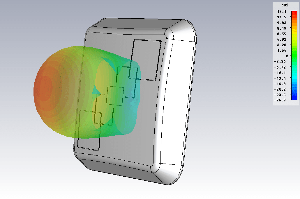
Figure 9. BAS 2301 WiFi antenna radiation pattern (f = 2.45 GHz)
The third option is a “wave channel” antenna in the WiFi range (2400-2500 MHz). In the performance of REMO, this is the BERKUT WiFi antenna (Figure 10). There are already 19 elements (6 of them are placed in a box on a printed circuit board), the maximum directional gain is 15 dBi.

Figure 10. Antenna Golden Eagle WiFi
All of the above methods, most often, will solve the problem. WiFi will appear in the right place, and with an excellent signal level. But there are some nuances:
- The price of the issue. These antennas are cheaper than a repeater, but their price is above 1000 rubles.
- Mounting. All such antennas require installation. It is necessary to mount the bracket. If you live in a rented apartment, then get the permission of the owner to fix this design. Also, this can lead to some inconvenience if you do not have the opportunity to mount the bracket on the wall yourself. I think the reader understands that it is not always possible to fix the bracket in view of various reasons, even despite the simplicity of this procedure.
- Accommodation. If in the version of the house or cottage you can install the antenna outdoors, stretching inward only the cable, then for an apartment this is not an option.
Another limitation on the use of such antennas is that not all routers have an antenna connector for connecting external antennas. The middle and budget segment is often not detachable antennas and, as a result, for such routers the above solutions are not suitable by definition.
Therefore, remote antennas are a good solution, but by no means applicable in all cases. What else can increase the coverage of WiFi networks?
We have been asking this question for a long time. What would you come up with that would be applicable in almost all cases, be effective, inexpensive and simple?
Perhaps the reader is familiar with our popular modem product.Connect 2.0 or its older versions.
The principle of operation is simple - using your own internal antenna of the device (modem) as an active element of the antenna system. So simplified, you can imagine the whole series of "amplifiers of the Internet signal."
We thought - is it possible to apply the same principle in a WiFi router with an external antenna?

Figure 11. Connect 2.0 Antenna
So, we have a router with an external antenna (important: we do not consider routers with a built-in antenna). The question arises: how to use this own antenna as an active element (vibrator) of the antenna system? Our goal is to give directional properties to the external antenna of the router, which will entail an increase in the transmission range and reception of the WiFi signal in a given direction. The first thing that comes to mind is the “wave channel” antenna, also known as “UDA-YAGI” (after the names of its inventors from Japan). This is a simple and at the same time effective antenna design, proven throughout the world.
So the idea came up and it had to be embodied in the design. The developers were faced with the task of calculating a multi-element wave channel in the range of 2.4-2.5 GHz, into which it would be possible to "embed" a standard router antenna. During the simulation, it was decided that the 7-element “wave channel” would be the best option. With quite compact dimensions of the structure, we got an antenna system, the amplification of which allows us to solve the tasks. The sizes of directors and the distances between them were optimized in the physical model, we consider them the best for solving the task (Fig. 12).

Figure 12. The “filling” of the BAS-2002 WiFi Ladder antenna
The next step was the development of the antenna mount design. After monitoring the router market, we decided to place the “wave channel” on the external antenna of the router, using it as a carrier element (Fig. 13). We are faced with the fact that routers have antennas of different diameters, and sometimes their shape is far from cylindrical or conical. For example, a “flattened” external antenna is very popular. For this reason, the designers have developed a universal clip that allows you to mount the product on almost any external router antenna. In some cases, this will not be the most rigid mount, but we want to note that the antenna is usually installed indoors and only once, so external physical influences on it will be minimal.

Figure 13. BAS-2002 WiFi Ladder antenna mounted on the external antenna of the router
A series of tests were carried out, during which the “shaded” areas of the room became covered by WiFi, and with a decent level (Fig. 14). The green color in the figure highlights the area with a good level of WiFi signal.
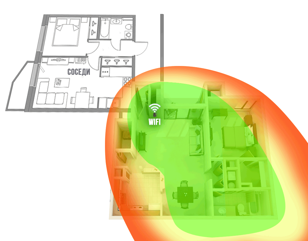
Figure 14. The coverage area of the WiFi network of the router with the antenna-nozzle
BAS-2002 WiFi Ladder in a typical apartment
The following is the radiation pattern of the developed antenna, which is mounted on the external antenna of a typical router (Fig. 15).
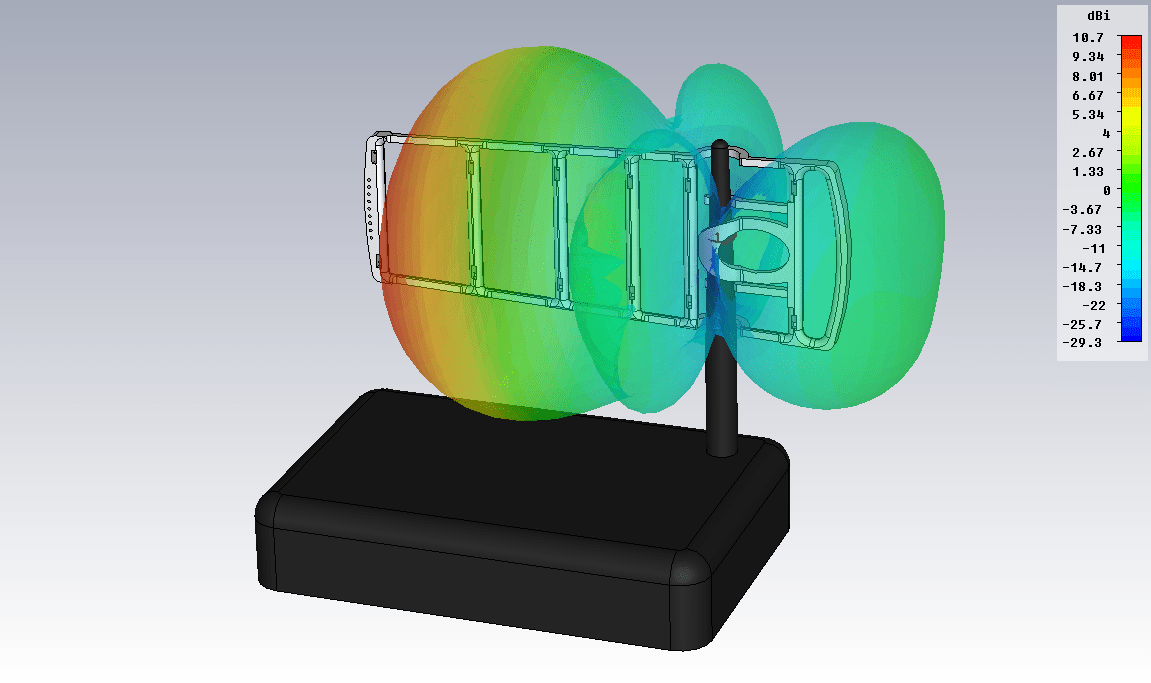
Figure 15. The pattern of the external antenna of the router with the antenna-attachment BAS-2002 WiFi Ladder
The antenna of the router acquired directional properties and, as a result, directional gain, as a result of which the range of WiFi signal transmission in a given direction increased. In red in fig. 15 shows the maximum radiation of the antenna - the direction in which the coverage area of the WiFi network will increase.
During development, the working name was firmly attached to the antenna - “ladder”, therefore, without thinking twice, we decided to name this product, translating it only into English, taking into account our export practice: “BAS-2002 WiFi Ladder”.
We can’t ignore one more question: in what place should the product be fixed on an external antenna?
After studying the design of the external antennas of different routers, we came to the conclusion that inside the plastic case the antennas are not always located as we expect (Figure 16).

Figure 16. “Inside” of one of the external antennas of the router.
As can be seen from Figure 16, the antenna is not located along the entire length of the plastic case, but only in its lower part.
Most often, the antenna structure is located in the lower or middle part of the plastic case. That is why the user needs to find the optimal height place for mounting on an external antenna (Fig. 17). It happens that the user forgets or ignores this important setting item and does not receive the expected result, so once again we recall that the height adjustment is important and required!
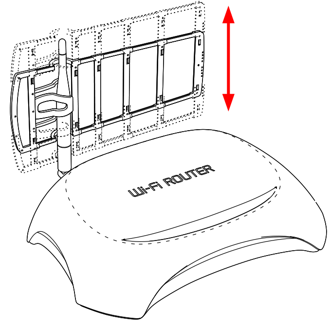
Figure 17. BAS-2002 WiFi Ladder
antenna height adjustment The antenna works in IEEE802.11 b / g / n networks using 2.4..2.5 GHz frequencies.
As we said earlier, there are routers with several external antennas. In this case, you can use the antenna attachment to all antennas or only one or two. Depends on the tasks. You can create maximum gain in one direction, then all antennas will be “aimed in one direction” and their gain will add up (Fig. 18).

Figure 18
You can strengthen WiFi in different directions, i.e. expand the coverage area:
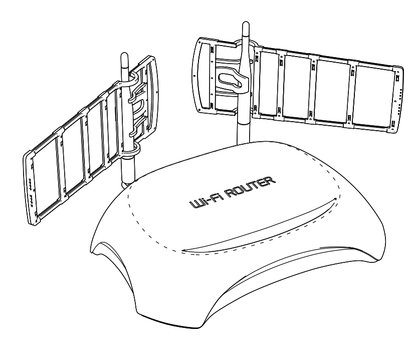
Figure 19
It is worth mentioning programs that will help to tune such antennas in the direction (not only WFi LADDER).
For Windows:
» WirelessNetView
» NetSpot
» Free Wi-Fi Scanner
For Linux:
» LinSSID(sourceforge.net/projects/linssid/)
" iwScanner
For OS X:
" NetSpot
We will be glad to know what programs the reader uses for similar purposes. Please note that some software may be presented in demo versions and have shareware distribution.
Feedback on the use of the antenna: remo-zavod.ru/news/otzyv-ob-antenne-wifi-direct
Use the BAS-2002 WiFi Ladder antenna if your router with an external antenna is not able to provide WiFi coverage in remote areas of the apartment or house.

Figure 1. The WiFi coverage area of the router network in a typical apartment (router next to the front door).
We produce passive and active antennas, including for data networks, WiFi. In this article, we are not so much interested in wireless access issues as in ways to increase WiFi coverage. Note that we do not consider specific options for creating special “powerful” access points. Everything is only within the framework of standards and norms adopted in the Russian Federation.
In our experience, the router is usually placed: next to the front door, in the corridor behind the cabinet, or in the distribution panel. In such cases, the area of the apartment is not uniformly covered by the WiFi network. Depending on the layout of the apartment, the far rooms, the kitchen, the loggia are outside the zone of sustainable coverage. (Example in Figure 1)
The same situation is true for a private house. The area of the house is usually larger, and the Internet is needed not only indoors, but also outside - at the barbecue area, pool, on the playground. Here the problem is more serious.
Figure 2. WiFi coverage area of the router network in a country house
Figures 1 and 2 show examples of WiFi coverage, green areas with a good network level are highlighted in green, red with a low level, which often does not allow you to work normally on the Internet. Note that the WiFi signal, being a radio wave, spreads better in free space, so the walls and other partitions in the room will weaken it and, as a result, reduce the level of the signal that passed through them.
The problem is identified - insufficient coverage of the WiFi network in the room. Let's see why this is happening. The router’s standard antenna has a circular radiation pattern - it radiates WiFi in all directions. Including towards your neighbors, which is usually pointless and not necessary. At the same time, the antenna’s own gain is relatively small, as a result of which, such an antenna has insufficient efficiency. As a result, the coverage area of the WiFi signal is small.
Figure 3. The radiation pattern of a standard router antenna (f = 2.45 GHz)
Figure 3 shows the radiation pattern of an external antenna of a standard router, calculated in a physical simulator. A dipole is used as an antenna.
How to improve WiFi coverage
The first thing that comes to mind is to replace the router with another one. Buy a device with a more powerful external antenna or with several antennas. If you have an outdated router model, then it's worth a try. Be prepared that this will require additional costs, and a positive result is not guaranteed at all. Most likely, the picture will improve, but the problem will not be resolved (Fig. 4-5).
Figure 4. A router with two external antennas.
Figure 5. A router with three external antennas.
The next way is to use an active WiFi repeater, it is also called a WiFi repeater. This device is just designed to increase the range of a WiFi network. A great way, often allowing you to solve the problem in the bud. But he has also disadvantages:
- prices from one and a half thousand rubles and higher;
- the need for customization;
- limited area of use.
And this is not all: the repeater will again receive a signal from all sides and radiate around. That is, if we have an “unreached” corner of the apartment far, then two or even three repeaters will be required. It would be great to concentrate the signal in a given direction, but it won’t work out - the built-in repeater antennas have a pie chart. Repeaters with a jack for an external antenna we did not meet.
It is worth mentioning another feature of the WiFi repeater - the presence of 220V mains power. Not all people are ready to leave some devices connected to the network when leaving home. And turn on and off every time - an activity for an amateur. In addition, for a house or cottage, the decision is complicated by the fact that between the house and, say, a barbecue area, most often there is no power supply, and repeaters are often not designed for outdoor use.
Figure 6. Principle of operation of the WiFi repeater
The next solution is to use an external directional antenna. The simplest thing is to unscrew the standard antenna from the router and connect a directional one that will focus the entire signal in the desired direction. Antennas of this kind are numerous, but we will focus on the development of our enterprise.
The first solution is the WiFi Extender antenna (Figure 7):
Figure 7. WiFi Extender Antenna
This is a wave channel indoor antenna in a transparent plastic case. Antenna gain 10 dBi.
The second option is more complex and effective - a panel antenna. In our case, BAS-2301 WiFi (Figures 8-9). Inside the radiotransparent sealed enclosure is a patch antenna. Gain of at least 12.5 dBi.
Figure 8. BAS 2301 WiFi antenna
Figure 9. BAS 2301 WiFi antenna radiation pattern (f = 2.45 GHz)
The third option is a “wave channel” antenna in the WiFi range (2400-2500 MHz). In the performance of REMO, this is the BERKUT WiFi antenna (Figure 10). There are already 19 elements (6 of them are placed in a box on a printed circuit board), the maximum directional gain is 15 dBi.
Figure 10. Antenna Golden Eagle WiFi
All of the above methods, most often, will solve the problem. WiFi will appear in the right place, and with an excellent signal level. But there are some nuances:
- The price of the issue. These antennas are cheaper than a repeater, but their price is above 1000 rubles.
- Mounting. All such antennas require installation. It is necessary to mount the bracket. If you live in a rented apartment, then get the permission of the owner to fix this design. Also, this can lead to some inconvenience if you do not have the opportunity to mount the bracket on the wall yourself. I think the reader understands that it is not always possible to fix the bracket in view of various reasons, even despite the simplicity of this procedure.
- Accommodation. If in the version of the house or cottage you can install the antenna outdoors, stretching inward only the cable, then for an apartment this is not an option.
Another limitation on the use of such antennas is that not all routers have an antenna connector for connecting external antennas. The middle and budget segment is often not detachable antennas and, as a result, for such routers the above solutions are not suitable by definition.
Therefore, remote antennas are a good solution, but by no means applicable in all cases. What else can increase the coverage of WiFi networks?
We have been asking this question for a long time. What would you come up with that would be applicable in almost all cases, be effective, inexpensive and simple?
Perhaps the reader is familiar with our popular modem product.Connect 2.0 or its older versions.
The principle of operation is simple - using your own internal antenna of the device (modem) as an active element of the antenna system. So simplified, you can imagine the whole series of "amplifiers of the Internet signal."
We thought - is it possible to apply the same principle in a WiFi router with an external antenna?
Figure 11. Connect 2.0 Antenna
Development of antenna nozzles for the router (WiFi Ladder)
So, we have a router with an external antenna (important: we do not consider routers with a built-in antenna). The question arises: how to use this own antenna as an active element (vibrator) of the antenna system? Our goal is to give directional properties to the external antenna of the router, which will entail an increase in the transmission range and reception of the WiFi signal in a given direction. The first thing that comes to mind is the “wave channel” antenna, also known as “UDA-YAGI” (after the names of its inventors from Japan). This is a simple and at the same time effective antenna design, proven throughout the world.
So the idea came up and it had to be embodied in the design. The developers were faced with the task of calculating a multi-element wave channel in the range of 2.4-2.5 GHz, into which it would be possible to "embed" a standard router antenna. During the simulation, it was decided that the 7-element “wave channel” would be the best option. With quite compact dimensions of the structure, we got an antenna system, the amplification of which allows us to solve the tasks. The sizes of directors and the distances between them were optimized in the physical model, we consider them the best for solving the task (Fig. 12).
Figure 12. The “filling” of the BAS-2002 WiFi Ladder antenna
The next step was the development of the antenna mount design. After monitoring the router market, we decided to place the “wave channel” on the external antenna of the router, using it as a carrier element (Fig. 13). We are faced with the fact that routers have antennas of different diameters, and sometimes their shape is far from cylindrical or conical. For example, a “flattened” external antenna is very popular. For this reason, the designers have developed a universal clip that allows you to mount the product on almost any external router antenna. In some cases, this will not be the most rigid mount, but we want to note that the antenna is usually installed indoors and only once, so external physical influences on it will be minimal.
Figure 13. BAS-2002 WiFi Ladder antenna mounted on the external antenna of the router
A series of tests were carried out, during which the “shaded” areas of the room became covered by WiFi, and with a decent level (Fig. 14). The green color in the figure highlights the area with a good level of WiFi signal.
Figure 14. The coverage area of the WiFi network of the router with the antenna-nozzle
BAS-2002 WiFi Ladder in a typical apartment
The following is the radiation pattern of the developed antenna, which is mounted on the external antenna of a typical router (Fig. 15).
Figure 15. The pattern of the external antenna of the router with the antenna-attachment BAS-2002 WiFi Ladder
The antenna of the router acquired directional properties and, as a result, directional gain, as a result of which the range of WiFi signal transmission in a given direction increased. In red in fig. 15 shows the maximum radiation of the antenna - the direction in which the coverage area of the WiFi network will increase.
During development, the working name was firmly attached to the antenna - “ladder”, therefore, without thinking twice, we decided to name this product, translating it only into English, taking into account our export practice: “BAS-2002 WiFi Ladder”.
We can’t ignore one more question: in what place should the product be fixed on an external antenna?
After studying the design of the external antennas of different routers, we came to the conclusion that inside the plastic case the antennas are not always located as we expect (Figure 16).
Figure 16. “Inside” of one of the external antennas of the router.
As can be seen from Figure 16, the antenna is not located along the entire length of the plastic case, but only in its lower part.
Most often, the antenna structure is located in the lower or middle part of the plastic case. That is why the user needs to find the optimal height place for mounting on an external antenna (Fig. 17). It happens that the user forgets or ignores this important setting item and does not receive the expected result, so once again we recall that the height adjustment is important and required!
Figure 17. BAS-2002 WiFi Ladder
antenna height adjustment The antenna works in IEEE802.11 b / g / n networks using 2.4..2.5 GHz frequencies.
As we said earlier, there are routers with several external antennas. In this case, you can use the antenna attachment to all antennas or only one or two. Depends on the tasks. You can create maximum gain in one direction, then all antennas will be “aimed in one direction” and their gain will add up (Fig. 18).
Figure 18
You can strengthen WiFi in different directions, i.e. expand the coverage area:
Figure 19
It is worth mentioning programs that will help to tune such antennas in the direction (not only WFi LADDER).
For Windows:
» WirelessNetView
» NetSpot
» Free Wi-Fi Scanner
For Linux:
» LinSSID(sourceforge.net/projects/linssid/)
" iwScanner
For OS X:
" NetSpot
We will be glad to know what programs the reader uses for similar purposes. Please note that some software may be presented in demo versions and have shareware distribution.
Feedback on the use of the antenna: remo-zavod.ru/news/otzyv-ob-antenne-wifi-direct
Summary
Use the BAS-2002 WiFi Ladder antenna if your router with an external antenna is not able to provide WiFi coverage in remote areas of the apartment or house.