Virtual GPIO driver with QEMU ivshmem interrupt controller for Linux
- Tutorial

It's hard to underestimate the role of GPIO , especially in the world of ARM embedded systems. Besides being extremely popular material for all beginner's guides, GPIOs provide a way to control many peripheral devices, act as a source of valuable interruptions, or even be the only available way to communicate with the world for SOC.
Based on my own modest experience, I can say that interrupts are far from the most consecrated topic in the Linux community. Due to its features, as well as a strong attachment to the hardware, all training materials on interruptions lack a real and easily reproducible example. This fact hinders the understanding that interrupts and GPIOs are often inseparable, especially in the field of embedded Linux. Many people begin to believe that GPIO is a very simple and boring thing (which by the way became such thanks to the sysfs subsystem).
Even in the example given in LDD3 (snull driver), interrupts are emitted by an explicit call to the paired device function. There are also examples in USFCA courses ( http://cs.usfca.edu/~cruse/cs686s08/ ), but they use someone else's interrupt, are closely related to the x86 architecture and are very outdated.
The proposed solution is able to solve these problems. From the point of view of user space and, in many ways, in the internal implementation, the driver is indistinguishable from most of the "real" ones, which provide interruptions to the general-purpose input / output ports. Currently, the driver supports trailing edges or trailing edges and can be used as a source of interrupts for other devices.
ivshmem - Inter-VM Shared Memory
Designed for sharing shared memory (allocated on the host platform through the POSIX shared memory API mechanism) by multiple QEMU processes with various guest platforms. In order for all guest platforms to have access to the shared memory area, ivshmem models a PCI device by providing memory access as a PCI BAR.
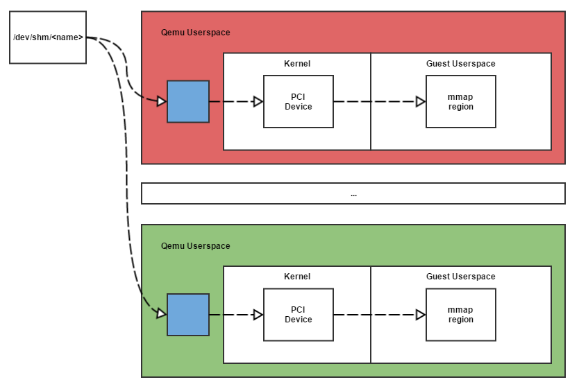
From a virtual machine perspective, an ivshmem PCI device contains three basic address registers (BARs).
- BAR0 is an MMIO area supporting registers and interrupts in case MSI is not used, one kilobyte in size
- BAR1 is used for MSI-X if MSI support is enabled.
- BAR2 to access the shared memory object.
This mechanism was introduced by Cam Macdonnel in the original report “Nahanni - a shared memory interface for KVM” (later became known as ivshmem), in which he put forward the following points:
- zero-copy data access
- interrupt mechanism
- guest / guest and host / guest interaction
and analyzed overall performance.
At present, officially, no one carries out ivshmem support, however, Red Hat employees make a big contribution to ivshmem development.
purpose
ivshmem can serve as the basis for simulating and debugging many device classes.
In this article, we consider a general-purpose input / output (GPIO) virtual pci board, which is also a source of interrupts, and the corresponding driver with access and control through the sysfs mechanism.
Prerequisites:
- Qemu 2.5.1.1 source code (it is not recommended to take a lower version)
- Source code linux-kernel 4.1
For development and testing, the virtual board qemu versatilepb (system ARM) was used.
Optionally:
- arm-cross-toolchain
- nairobi-embedded - Guest-side ivshmem PCI device test sources
Legend:
g >> - commands or output executed on the guest system.
h >> on the main one.
Example and original code
To begin with, we will demonstrate the original code based on the original code ( https://github.com/henning-schild/ivshmem-guest-code ), and a modified, later Siro Mugabi.
h>> qemu: +=  -device ivshmem,shm=ivshmem,size=1
g>> # insmod ne_ivshmem_ldd_basic.ko
ivshmem 0000:00:0d.0: data_mmio iomap base = 0xc8c00000
ivshmem 0000:00:0d.0: data_mmio_start = 0x60000000 data_mmio_len = 1048576
ivshmem 0000:00:0d.0: regs iomap base = 0xc88ee400, irq = 27
ivshmem 0000:00:0d.0: regs_addr_start = 0x50002400 regs_len = 256
g>> # ./ne_ivshmem_shm_guest_usr -w "TEST STRING"
h>> $ xxd -l 16 /dev/shm/ivshmem
0000000: 5445535420535452 494e 4700 0000 0000  TEST STRING.....
In principle, this is enough to emulate the GPIO already in this form. And in many cases, they did so when a simple state of entry or entry into the exit is sufficient, the use of sysfs and interrupts suggest a small add-on to I / O mem.
Implementation
Note that / dev / ivshmem0 and ne_ivshmem_shm_guest_usr.c are no longer needed, all work with the device from the guest machine from user space will be done using the sysfs interface .
Before marking our device in memory, I would like to note that we simply duplicate the scheme used in most gpio drivers.
Firstly, all gpio I / O are divided into ports, usually 8, 16, 32 inputs. Each port has at least an input status register ( GPIO_DATA ), a direction register, if in / out switching is supported ( GPIO_OUTPUT) Further (if there is support in the device itself), the interrupt status register, interrupt registers on the rising edge (falling) and falling edge (falling) and in level (high and low). The hardware interrupt supplied by the main interrupt controller is usually one on the entire port and is shared between all port inputs.
Examples of existing implementations with comments
Sitara am335x
better known as a beaglebone board
Developer: Texas Instruments
Documentation: AM335x Sitara Processors Technical Reference Manual (page 4865)
Corresponding gpio driver: linux / drivers / gpio / gpio-omap.c
Corresponding header: linux / include / linux / platform_data / gpio -omap.h
Number of inputs / outputs: 128 (4 gpio ports - 32 contacts each)
am335x Sitara gpio register table - port A
| Register name | Bias | Name in driver | Comment |
|---|---|---|---|
| GPIO_IRQSTATUS_0 | 0x02C | OMAP4_GPIO_IRQSTATUS_0 | Interrupt status for a given input |
| GPIO_IRQSTATUS_1 | 0x030 | OMAP4_GPIO_IRQSTATUS_1 | Состояние прерывания для заданного входа |
| GPIO_IRQSTATUS_SET_0 | 0x034 | OMAP4_GPIO_IRQSTATUS_SET_0 | Включает прерывания по заданному входу |
| GPIO_IRQSTATUS_SET_1 | 0x038 | OMAP4_GPIO_IRQSTATUS_SET_1 | Включает прерывания по заданному входу |
| GPIO_IRQSTATUS_CLR_0 | 0x03С | OMAP4_GPIO_IRQSTATUS_CLR_0 | Выключает прерывания по заданному входу |
| GPIO_IRQSTATUS_CLR_1 | 0x040 | OMAP4_GPIO_IRQSTATUS_CLR_1 | Выключает прерывания по заданному входу |
| GPIO_OE | 0x134 | OMAP4_GPIO_OE | Контролирует состояние вход/выход (in/out) |
| GPIO_DATAIN | 0x138 | OMAP4_GPIO_DATAIN | Состояние входа/выхода |
| GPIO_DATAOUT | 0x13C | OMAP4_GPIO_DATAOUT | Задание состояния для выходов (low/high) |
| GPIO_LEVELDETECT0 | 0x140 | OMAP4_GPIO_LEVELDETECT0 | Включение/выключения прерывания для входа по низкому уровню сигнала |
| GPIO_LEVELDETECT1 | 0x144 | OMAP4_GPIO_LEVELDETECT1 | Включение/выключения прерывания для входа по высокому уровню сигнала |
| GPIO_RISINGDETECT | 0x148 | OMAP4_GPIO_RISINGDETECT | Включение/выключения прерывания для входа по переднему фронту |
| GPIO_FALLINGDETECT | 0x14С | OMAP4_GPIO_FALLINGDETECT | Включение/выключения прерывания для входа по заднему фронту |
| GPIO_CLEARDATAOUT | 0x190 | OMAP4_GPIO_CLEARDATAOUT | Переключает соответствующий вход в состояние low |
| GPIO_SETDATAOUT | 0x194 | OMAP4_GPIO_SETDATAOUT | Переключает соответствующий вход в состояние high |
Note: GPIO_IRQSTATUS_N is also used for IRQ ACK. Managing bounce and eating is beyond the scope of this article.
The presence of the GPIO_CLEARDATAOUT and GPIO_SETDATAOUT registers in addition to the GPIO_DATAOUT register, as well as GPIO_IRQSTATUS_SET_N and GPIO_IRQSTATUS_CLR_N in addition to GPIO_IRQSTATUS_N, is explained by two ways of recording the output status:
- Standard: Read register entry completely at primary address
- Setting and cleaning (recommended by the manufacturer): To set and clear the corresponding contact as an output, two corresponding registers are used, the same applies to interrupt control.
ep9301
Developer: Cirrus Logic
Documentation: EP9301 User's Guide (page 523)
Its corresponding gpio driver: linux / drivers / gpio / gpio-ep93xx.c
Corresponding header: linux / arch / arm / mach-ep93xx / include / mach / gpio-ep93xx. h
Number of inputs / outputs: 56 (7 gpio ports - 8 contacts each)
ep9301 gpio register table - port A
| Имя регистра | Смещение | Имя в драйвере | Описание |
|---|---|---|---|
| PADR | 0x00 | EP93XX_GPIO_REG(0x0) | Регистр состояние входов/выходов доступен для чтения записи |
| PADDR | 0x10 | EP93XX_GPIO_REG(0x10) | Контролирует состояние вход/выход (in/out) |
| GPIOAIntEn | 0x9C | int_en_register_offset[0] | Включает прерывания по заданному входу |
| GPIOAIntType1 | 0x90 | int_type1_register_offset[0] | Задает тип прерывания level/edge |
| GPIOAIntType2 | 0x94 | int_type2_register_offset[0] | Задает high/rising или low/fallingв зависимости от выбранного типа прерываний |
| GPIOAEOI | 0x98 | eoi_register_offset[0] | Регистр для оповещения об обработанном прерывании |
| IntStsA | 0xA0 | EP93XX_GPIO_A_INT_STATUS | Регистр состояние прерывания |
Note:
Of these, 7 ports are available for 8, 8, 1, 2, 3, 2, 4 inputs / outputs, and only the first, second, and fifth ports have interrupt registers.
Only port A is considered in the table.
One of the features of ep9301 is that the type of both interrupts is not supported at the hardware level, the driver switches at the moment the interrupt is triggered. Another interesting feature - on port F, each contact has its own interrupt.
Bt848
Last example: pci board Bt848, with gpio.
Developer: Intel
Documentation: Bt848 / 848A / 849A (page 68)
Corresponding gpio driver: linux / drivers / gpio / gpio-bt8xx.c
Corresponding header: linux / drivers / media / pci / bt8xx / bt848.h
Number of inputs / outputs: 24
Bt848 is a video capture card.
Bt848 gpio register table
| Имя регистра | Смещение | Имя в драйвере | Описание |
|---|---|---|---|
| BT848_GPIO_OUT_EN | 0x118 | BT848_GPIO_OUT_EN | Регистр состояние входов/выходов доступен для чтения и записи |
| BT848_GPIO_DATA | 0x200 | BT848_GPIO_DATA | Контролирует состояние вход/выход (in/out) |
No interrupt support. Only two registers - status and in / out setting.
Marking our device in memory
First, let's allocate space for data and state management.
Let the device has 8 general-purpose inputs / outputs, then:
| Register name | Bias | Name in driver | Description |
|---|---|---|---|
| DATA | 0x00 | VIRTUAL_GPIO_DATA | I / O Status Register Readable and Writable |
| OUTPUTEN | 0x01 | VIRTUAL_GPIO_OUT_EN | Monitors in / out status |
Gpio interface quick reference
struct gpio_chip {
  /* имя порта gpio */constchar *label;
  /* функция задания как входа */int (*direction_input)(struct gpio_chip *chip, unsigned offset);
  /* состояние контакта */int (*get)(struct gpio_chip *chip, unsigned offset);
  /* функция задания как выхода */int (*direction_output)(struct gpio_chip *chip, unsigned offset, intvalue);
  /* задание состояния */void (*set)(struct gpio_chip *chip, unsigned offset, intvalue);
  /* номер первого контакта в контексте ядра, присваивается динамически в случае значения равном -1 */intbase;
  /* количество контактов */
  u16 ngpio;
};
Documentation: https://www.kernel.org/doc/Documentation/gpio/sysfs.txt Source link: linux-kernel 4.1
Switch output status
It is necessary to note the int value parameter in the direction_output function , which serves the file / sys / class / gpio / gpioN / direction, which takes the value not only “in” / ”out”, but also “high” / “low”, the values of which are passed as a value parameter ( this simple fact, for some reason, is rarely mentioned in beginner's manuals ).
g>> /sys/class/gpio # echo low > gpio0/direction
g>> /sys/class/gpio # cat gpio0/value
0
g>> /sys/class/gpio # echo high > gpio0/direction
g>> /sys/class/gpio # cat gpio0/value
1
Dynamic int base assignment and legacy ARCH_NR_GPIOS
Historically, the number of GPIOs in the kernel was limited by the ARCH_NR_GPIOS parameter , which defaults to 256 and subsequently increased to 512 ( version 3.18 ).
Its meaning is quite simple, in the kernel there can be no more GPIO than the parameter value, if the planned amount was more than the default value, it was redefined in the corresponding platform header file.
The reason for this behavior was to define the GPIO description table as static and the maximum offset for each port was limited:
staticstructgpio_descgpio_desc[ARCH_NR_GPIOS];GPIO ports and their offsets were hardcoded in files describing the hardware of a particular SOC, for example:
EP93XX_GPIO_BANK
/source/arch/arm/mach-ep93xx/gpio.c
#define EP93XX_GPIO_BANK(name, dr, ddr, base_gpio)                       \
       {                                                                 \
               .chip = {                                                 \
                       .label             = name,                        \
                       .direction_input   = ep93xx_gpio_direction_input, \
                       .direction_output  = ep93xx_gpio_direction_output,\
                       .get               = ep93xx_gpio_get,             \
                       .set               = ep93xx_gpio_set,             \
                       .dbg_show          = ep93xx_gpio_dbg_show,        \
                       .base              = base_gpio,                   \
                       .ngpio             = 8,                           \
               },                                                        \
               .data_reg       = EP93XX_GPIO_REG(dr),                    \
               .data_dir_reg   = EP93XX_GPIO_REG(ddr),                   \
       }
staticstruct ep93xx_gpio_chip ep93xx_gpio_banks[] = {
       EP93XX_GPIO_BANK("A", 0x00, 0x10, 0),
       EP93XX_GPIO_BANK("B", 0x04, 0x14, 8),
       EP93XX_GPIO_BANK("C", 0x08, 0x18, 40),
       EP93XX_GPIO_BANK("D", 0x0c, 0x1c, 24),
       EP93XX_GPIO_BANK("E", 0x20, 0x24, 32),
       EP93XX_GPIO_BANK("F", 0x30, 0x34, 16),
       EP93XX_GPIO_BANK("G", 0x38, 0x3c, 48),
       EP93XX_GPIO_BANK("H", 0x40, 0x44, 56),
};
Starting with version 3.19, the static array was replaced by dynamic ones for each GPIO port allocated in the gpiochip_add () function .
However, ARCH_NR_GPIOS is still here (at the time of version 4.7) and is used to find the offset for dynamic base assignment.
/* dynamic allocation of GPIOs, e.g. on a hotplugged device */staticintgpiochip_find_base(int ngpio);The base parameter of the gpio_chip structure can be defined as -1, then the offset will be defined as the first free range starting from the end, that is, if the port has 8 contacts, the offset will be 248 with the ARCH_NR_GPIOS parameter equal to 256 ( ARCH_NR_GPIOS - ngpio) if the port registered in the system first.
We define the following functions of our driver
Set the corresponding contact as input:
static int virtual_gpio_direction_input (struct gpio_chip * gpio, unsigned nr)
static int virtual_gpio_direction_input(struct gpio_chip *gpio, unsigned nr)
{
   struct virtual_gpio *vg = to_virtual_gpio(gpio);
   unsigned long flags;
   u8 outen, data;
   spin_lock_irqsave(&vg->lock, flags);
   data = vgread(VIRTUAL_GPIO_DATA);
   data &= ~(1 << nr);
   vgwrite(data, VIRTUAL_GPIO_DATA);
   outen = vgread(VIRTUAL_GPIO_OUT_EN);
   outen &= ~(1 << nr);
   vgwrite(outen, VIRTUAL_GPIO_OUT_EN);
   spin_unlock_irqrestore(&vg->lock, flags);
   return 0;
}
Reading the current state of the contact:
static int virtual_gpio_get (struct gpio_chip * gpio, unsigned nr)
static int virtual_gpio_get(struct gpio_chip *gpio, unsigned nr)
{
   struct virtual_gpio *vg = to_virtual_gpio(gpio);
   unsigned long flags;
   u8 data;
   spin_lock_irqsave(&vg->lock, flags);
   data= vgread(VIRTUAL_GPIO_DATA);
   spin_unlock_irqrestore(&vg->lock, flags);
   return !!(data & (1 << nr));
}
Set the corresponding contact as output:
static int virtual_gpio_direction_output (struct gpio_chip * gpio, unsigned nr, int val)
static int virtual_gpio_direction_output(struct gpio_chip *gpio, unsigned nr, int val)
{
   struct virtual_gpio *vg = to_virtual_gpio(gpio);
   unsigned long flags;
   u8 outen, data;
   spin_lock_irqsave(&vg->lock, flags);
   outen = vgread(VIRTUAL_GPIO_OUT_EN);
   outen |= (1 << nr);
   vgwrite(outen, VIRTUAL_GPIO_OUT_EN);
   data = vgread(VIRTUAL_GPIO_DATA);if (val)
       data |= (1 << nr);elsedata &= ~(1 << nr);
   vgwrite(data, VIRTUAL_GPIO_DATA);
   spin_unlock_irqrestore(&vg->lock, flags);
   return 0;
}
Set output status:
static void virtual_gpio_set (struct gpio_chip * gpio, unsigned nr, int val)
static void virtual_gpio_set(struct gpio_chip *gpio, unsigned nr, int val)
{
   struct virtual_gpio *vg = to_virtual_gpio(gpio);
   unsigned long flags;
   u8 data;
   spin_lock_irqsave(&vg->lock, flags);
   data = vgread(VIRTUAL_GPIO_DATA);if (val)
       data |= (1 << nr);elsedata &= ~(1 << nr);
   vgwrite(data, VIRTUAL_GPIO_DATA);
   spin_unlock_irqrestore(&vg->lock, flags);
}
The function of registering our driver as a gpio_chip device:
static void virtual_gpio_setup (struct virtual_gpio * gpio)
static void virtual_gpio_setup(structvirtual_gpio *gpio)
{
   structgpio_chip *chip = &gpio->chip;
   chip->label = dev_name(&gpio->pdev->dev);
   chip->owner = THIS_MODULE;
   chip->direction_input = virtual_gpio_direction_input;
   chip->get = virtual_gpio_get;
   chip->direction_output = virtual_gpio_direction_output;
   chip->set = virtual_gpio_set;
   chip->dbg_show = NULL;
   chip->base = modparam_gpiobase;
   chip->ngpio = VIRTUAL_GPIO_NR_GPIOS;
   chip->can_sleep = 0; // gpio never sleeps!
}
vgread and vgwrite are just wrappers for the iowrite8 and ioread8 functions:
#define vgwrite(dat, adr)   iowrite8((dat), vg->data_base_addr+(adr))
#define vgread(adr)         ioread8(vg->data_base_addr+(adr))
Passing gpiobase value as a parameter during module dynamic loading
Note: Starting with version 4.2, this is the recommended way to register a GPIO port.
staticint modparam_gpiobase = -1; /* dynamic */
module_param_named(gpiobase, modparam_gpiobase, int, 0444);
MODULE_PARM_DESC(gpiobase, "The GPIO base number. -1 means dynamic, which is the default.");
Loading and testing the module
h>> $ rm /dev/shm/ivshmem
h>> Adding parameters to qemu launch command line  += -device ivshmem,shm=ivshmem,size=1
g>> # ls /sys/class/gpio/export    unexport
g>> # insmod virtual_gpio_basic.ko
PCI: enabling device 0000:00:0d.0 (0100 -> 0102)
ivshmem_gpio 0000:00:0d.0: data_mmio iomap base = 0xc8a00000
ivshmem_gpio 0000:00:0d.0: data_mmio_start = 0x60000000 data_mmio_len = 1048576
ivshmem_gpio 0000:00:0d.0: regs iomap base = 0xc88e6400, irq = 27
ivshmem_gpio 0000:00:0d.0: regs_addr_start = 0x50002400 regs_len = 256
g>> # ls /sys/class/gpio/export       gpiochip248  unexport
g>> # cat /sys/class/gpio/gpiochip248/label
0000:00:0d.0
g>> # cat /sys/class/gpio/gpiochip248/base
248
g>> # cat /sys/class/gpio/gpiochip248/ngpio
8
g>> # rmmod virtual_gpio_basic
Unregister virtual_gpio device.
g>> # insmod virtual_gpio_basic.ko gpiobase=0
g>> # ls /sys/class/gpio/export     gpiochip0  unexport
g>> # echo 0 > /sys/class/gpio/export
g>> # echo high > /sys/class/gpio/gpio0/direction
Simple check:
h>>  $ xxd -b -l 2 -c 2 /dev/shm/ivshmem
0000000: 00000001 00000001  ..
DATA on, OUTPUTEN on.
Add interrupts
Interrupt register markup and basic interrupt handling
Note: Only EDGEDETECT_RISE and EDGEDETECT_FALL are considered in the virtual driver.
Note: Please use only qemu versions older than 2.5.0 or qemu-linaro. The ivshmem interrupt support is broken in 2.5.0 or just does not work on some versions under 2.5.0. If using 2.5.0 you must use the patch for 2.5.0 ( http://lists.gnu.org/archive/html/qemu-stable/2015-12/msg00034.html ).
Add the following registers:
| Register name | Bias | Name in driver | Description |
|---|---|---|---|
| INTERRUPT_EN | 0x01 | VIRTUAL_GPIO_INT_EN | Enables setpoint interrupts |
| INTERRUPT_ST | 0x02 | VIRTUAL_GPIO_INT_ST | Interrupt Status Register |
| INTERRUPT_EOI | 0x03 | VIRTUAL_GPIO_INT_EOI | Register for notification of processed interrupt |
| EDGEDETECT_RISE | 0x04 | VIRTUAL_GPIO_RISING | Turn on / off interrupt for rising edge input |
| EDGEDETECT_FALL | 0x05 | VIRTUAL_GPIO_FALLING | Turn on / off interrupt for trailing edge entry |
| LEVELDETECT_HIGH | NC | NOT CONNECTED | |
| LEVELDETECT_LOW | NC | NOT CONNECTED |
The following function is responsible for processing the interrupt from the pci bus, at the moment its role is only to notify about the processed interrupt:
static irqreturn_t virtual_gpio_interrupt (int irq, void * data)
static irqreturn_t virtual_gpio_interrupt(int irq, void *data)
 {
       u32 status;
       structvirtual_gpio *vg = (structvirtual_gpio *)data;
       status = readl(vg->regs_base_addr + IntrStatus);
       if (!status || (status == 0xFFFFFFFF))
               return IRQ_NONE;
       printk(KERN_INFO "VGPIO: interrupt (status = 0x%04x)\n", status);
       return IRQ_HANDLED;
 }
For this stage, an external daemon is required, which is included in the standard qemu delivery - ivshmem-server. The -chardev path to the UNIX socket is added to the qemu launch line, the exchange of messages between running qemu, ivshmem-server and ivshmem-client instances is implemented using the eventfd mechanism.
h>> $ ivshmem-server -v -F -p ivshmem.pid -l 1M
# запускаем qemu с новыми параметрами
h>> $ += -chardev socket,path=/tmp/ivshmem_socket,id=ivshmemid -device ivshmem,chardev=ivshmemid,size=1,msi=off
g>> # echo 8 > /proc/sys/kernel/printk
g>> # insmod virtual_gpio_basic.ko
h>> $ ivshmem-client
# каждый экземпляр qemu ivshmem региструет себя в ivshmem-server и ему присваивается уникальный id
cmd> int 0 0
# Примечание: листинг доступных команд можно посмотреть командой cmd> help# Вывод гостевой машины:
g>> VGPIO: interrupt (status = 0x0001)
irq_chip and the concept of chained_interrupt
We will not go into details, this topic was well disclosed in the first patch introducing irq_chip , kernel documentation, and the book “Professional Linux Kernel Architecture” (it is outdated to date, but irq_chip is also not a new thing).
At the moment, the main fact for us is that the GPIO ports providing interrupts cascaded from the parent interrupt controller are common practice in the days of modern Linux.
This is why the interrupt part of the GPIO driver uses irq_chip . In other words, such a driver uses two subsystems simultaneously: gpio_chip and irq_chip .
A quick look at the irq subsystem gives us the following picture:

High-Level Interrupt Service Routines (ISRs) - Performs all necessary interrupt service work on the device driver. For example, if an interrupt is used to indicate readable new data, the operation of the ISR will be to copy the data to the appropriate location.
Interrupt Flow Handling - This subsystem is responsible for features in the implementation of interrupt handling, such as triggering by signal level (level) or edge (edge).
Edge triggering occurs when it is determined that a potential change has occurred on the line. Triggering by level (Level-triggering), is defined as a certain value of the potential, while the change in potential does not play a role.
From the point of view of the kernel, triggering by level is a more complicated case, since, after the beginning of each interruption, it must be masked.
Chip-Level Hardware Encapsulation - Used to encapsulate the features of the implementation of work with the hardware. This subsystem can be considered as a kind of “device driver” for interrupt controllers.
As we can see, the kernel takes control of the processing of the interrupt chain and the difference in the implementation of types (front and level), if you provide the appropriate infrastructure.
IRQ Domains
The IRQ Domain subsystem that appeared in the irq: add irq_domain translation infrastructure patch made it possible to separate interrupt numbers local to the controller from interrupt numbers in the kernel, providing a common array of interrupt numbers. Quoting the official documentation: “Today is an IRQ number, it's just a number . ”
Prior to this update, hardware numbers were mapped to kernel numbers as 1: 1, and cascading was not supported. By hardware numbers, we mean local interrupt numbers for the controller, which in our case coincide with local GPIO numbers.
The following display types exist in the IRQ Domain:
- Linear
- Tree view
- And type "No map" (No display)
Since our interrupt vector is small enough, and we definitely have no interest in the "No map" map, our map is linear, in fact, the numbers are mapped 1: 1 to the offset, the difference with the old approach is that it assigns irq numbers and calculates the offset core, while ensuring the continuity of the allocated range.
A pointer to the struct irq_data structure is passed to each function of the irq_chip interface , where irq_data-> irq is the interrupt number in the linux kernel, and irq_data-> hwirq is our local interrupt number in the driver. A pointer to our struct virtual_gpio structure is also passed to struct irq_data , which is not surprising.
Binding irq_chip and gpio_chip
If we were guided by lower versions of the kernel, we would have to use the irq_domain_add_simple function to display our number, but since version 3.15 in the gpio patch : add IRQ chip helpers in gpiolib patch there is no need to directly use the IRQ Domain interface.
Therefore, instead of directly using the IRQ Domain interface and providing the infrastructure for mapping local numbers to global ( .map () ops), we will use the gpiochip_irqchip_add and gpiochip_set_chained_irqchip functions (depending on the GPIOLIB_IRQCHIP Kconfig parameter).
A great example of use and ease of use is the gpio-pl061 driver .
Bind our irq_chip to the existing gpio_chip :
gpiochip_irqchip_add(&vg->chip,
                     &virtual_gpio_irq_chip,
                     0,
                     handle_edge_irq,
                     IRQ_TYPE_NONE);
handle_edge_irq is one of the built-in stream handlers that takes control of the edge interrupt chain.
Note: edge interruption is the most common. The main difference from interruptions in level is precisely in chain management, interruption in level is masked in the kernel immediately after receipt.
gpiochip_set_chained_irqchip(&vg->chip,
                             &virtual_gpio_irq_chip,
                             pdev->irq,
                             NULL);
By calling the gpiochip_set_chained_irqchip function , we inform the kernel that our irq_chip uses an interrupt from the PCI bus and our interrupt is cascaded from pdev-> irq .
We will modify our handler so that it generates interrupts depending on the state of VIRTUAL_GPIO_INT_ST :
pending = vgread(VIRTUAL_GPIO_INT_ST);
/* check if irq is really raised */if(pending)
{
    for_each_set_bit(i, &pending, VIRTUAL_GPIO_NR_GPIOS)
        generic_handle_irq(irq_find_mapping(vg->chip.irqdomain, i));
}
irq_find_mapping - an auxiliary function for translating the local input number to the global interrupt number.
Putting it all together
First of all, we note that the irq_chip interface of our driver looks as follows:
staticstructirq_chipvirtual_gpio_irq_chip = {
    .name           = "GPIO",
    .irq_ack        = virtual_gpio_irq_ack,
    .irq_mask       = virtual_gpio_irq_mask,
    .irq_unmask     = virtual_gpio_irq_unmask,
    .irq_set_type   = virtual_gpio_irq_type,
};
The ack () function is always closely related to the hardware specifics of the controller. Some devices, for example, require acknowledgment of interrupt request processing before subsequent requests can be serviced.
static void virtual_gpio_irq_ack (struct irq_data * d)
static void virtual_gpio_irq_ack(structirq_data *d)
{
   unsigned long flags;
   u8 nr = d->hwirq;
   u8 mask = 1 << nr;
   structgpio_chip *gc = irq_data_get_irq_chip_data(d);
   structvirtual_gpio *vg = to_virtual_gpio(gc);
   spin_lock_irqsave(&vg->lock, flags);
   vgwrite(mask, VIRTUAL_GPIO_INT_EOI);
   spin_unlock_irqrestore(&vg->lock, flags);
}
In our case, the program vg_get_set uses rather crude emulation of the eoi register. After setting the interrupt status flag, the eoi register is constantly polled in the loop. When the interrupt notification input bit is set by the driver, the eoi register is reset and the interrupt status bit on the input is cleared.
Masking and unmasking is done by writing the corresponding value to the register INTERRUPT_EN .
Interrupt Masking:
static void virtual_gpio_irq_mask (struct irq_data * d)
static void virtual_gpio_irq_mask(structirq_data *d)
{
  u8 mask;
  unsigned long flags;
  u8 nr = d->hwirq;
  structgpio_chip *gc = irq_data_get_irq_chip_data(d);
  structvirtual_gpio *vg = to_virtual_gpio(gc);
  spin_lock_irqsave(&vg->lock, flags);
  mask = vgread(VIRTUAL_GPIO_INT_EN);
  mask &= ~(1 << nr);
  vgwrite(mask, VIRTUAL_GPIO_INT_EN);
  spin_unlock_irqrestore(&vg->lock, flags);
}
Unmask Interrupt:
static void virtual_gpio_irq_unmask (struct irq_data * d)
static void virtual_gpio_irq_unmask(structirq_data *d)
{
  u8 mask;
  unsigned long flags;
  u8 nr = d->hwirq;
  structgpio_chip *gc = irq_data_get_irq_chip_data(d);
  structvirtual_gpio *vg = to_virtual_gpio(gc);
  spin_lock_irqsave(&vg->lock, flags);
  mask = vgread(VIRTUAL_GPIO_INT_EN);
  mask |= (1 << nr);
  vgwrite(mask, VIRTUAL_GPIO_INT_EN);
  spin_unlock_irqrestore(&vg->lock, flags);
}
irq_type allows you to specify the type of trigger - currently the following types are defined in the kernel:
IRQ_TYPE_NONE - no type specified
IRQ_TYPE_EDGE_RISING - leading edge
IRQ_TYPE_EDGE_FALLING - leading edge IRQ_TYPE_EDGE_BOTH - leading edge
and
high level
IRQ_LELE_LEVEL_LEVEL_LEIGHT_LEIGHT_LEIGHT_TYPE_LOT_LOT_LIGHT
static int virtual_gpio_irq_type (struct irq_data * d, unsigned int type)
staticintvirtual_gpio_irq_type(struct irq_data *d, unsignedint type){
  unsignedlong flags;
  structgpio_chip *gc = irq_data_get_irq_chip_data(d);structvirtual_gpio *vg = to_virtual_gpio(gc);
  u8 mask;
  u8 nr = d->hwirq;
  spin_lock_irqsave(&vg->lock, flags);
  switch (type) {
  case IRQ_TYPE_EDGE_RISING:
      mask = vgread(VIRTUAL_GPIO_RISING);
      mask |= (1 << nr);
      vgwrite(mask, VIRTUAL_GPIO_RISING);
      mask = vgread(VIRTUAL_GPIO_FALLING);
      mask &= ~(1 << nr);
      vgwrite(mask, VIRTUAL_GPIO_FALLING);
      break;
  case IRQ_TYPE_EDGE_FALLING:
      mask = vgread(VIRTUAL_GPIO_FALLING);
      mask |= (1 << nr);
      vgwrite(mask, VIRTUAL_GPIO_FALLING);
      mask = vgread(VIRTUAL_GPIO_RISING);
      mask &= ~(1 << nr);
      vgwrite(mask, VIRTUAL_GPIO_RISING);
      break;
  default:
      retval = -EINVAL;
      goto end;
  }
  /* enable interrupt */
  mask = vgread(VIRTUAL_GPIO_INT_EN);
  mask &= ~(1 << nr);
  vgwrite(mask, VIRTUAL_GPIO_INT_EN);
end:
  spin_unlock_irqrestore(&vg->lock, flags);
  return retval;
}
Testing and Results
To test the transfer of information about interrupts to user space, we will use the specially written utility vg_guest_client. According to the gpio_sysfs documentation, “If you use select to track events, set the file (descriptor) descriptor to exceptfds” .
Relevant Code:
 FD_ZERO(&efds);
 maxfd = 0;
 for(i = 0; i < gpio_size; i++)
 {
     FD_SET(gpios[i].fd, &efds);
     maxfd = (maxfd < gpios[i].fd) ? gpios[i].fd : maxfd;
 }
 ready = pselect(maxfd + 1, NULL, NULL, &efds, NULL, NULL);
 if(ready > 0)
     for(i = 0; i < gpio_size; i++)
         if(FD_ISSET(gpios[i].fd, &efds)) {
             read(gpios[i].fd, &value, 1);
 /* для пояснений использования lseek  смотрите http://lxr.free-electrons.com/source/fs/kernfs/file.c?v=4.1#L769 */
             if(lseek(gpios[i].fd, 0, SEEK_SET) == -1)
                 perror("lseek");
             printf("gpio number=%d interrupt caught\n", gpios[i].number);
         }
We prepare the inputs for work using sysfs :
g>> # echo 504 > /sys/class/gpio/export
g>> # echo 505 > /sys/class/gpio/export
g>> # echo 506 > /sys/class/gpio/export
g>> # echo rising > /sys/class/gpio/gpio504/edge
g>> # echo rising > /sys/class/gpio/gpio505/edge
g>> # echo rising > /sys/class/gpio/gpio506/edge
Note: gpio on the vast majority of devices is initialized as inputs by default.
# в качестве аргумента используется номер gpiochip в системе
g>> # ./vg_guest_client 504
gpio_chip:
       base: 504
       ngpio: 8
Added gpio 504 to watchlist.
Added gpio 505 to watchlist.
Added gpio 506 to watchlist.
Entering loop with 3 gpios.
h>> $ ./vg_get_set -p 1 -i 0
g>> gpio number=504 interrupt caught
The chain of calls from our interrupt handler to the pselect notification:
static irqreturn_t virtual_gpio_interrupt (int irq, void *data)
intgeneric_handle_irq(unsigned int irq);
...
static irqreturn_t gpio_sysfs_irq(int irq, void *priv);
static inline voidsysfs_notify_dirent(struct kernfs_node *kn);
voidkernfs_notify(struct kernfs_node *kn);
staticvoidkernfs_notify_workfn(struct work_struct *work);
Conclusion
This article was implied by me as the basis for material that is difficult, or even impossible, to imagine without any general introduction. Qemu paired with ivshmem provided an excellent and understandable basis for this purpose. The reason for choosing this particular bundle is the availability of sane documentation and transparency of use.
The work with gpio sysfs itself is no different for any devices with implemented sysfs support, any instructions for using GPIO can be successfully applied to another similar device, as was intended when developing this interface. All differences end at the specific device driver level.
The driver itself, despite its unconditional educational value, is far from ideal in the context of the modern core. For such a simple driver, you should usegeneric-gpio driver designed to avoid similar, repetitive code for mmio gpio drivers, the use of which, however, is not so obvious. Interrupt handling could be made more elegant, and register offset values are best stored in the driver structure.
Nevertheless, taking this driver as a basis, the following topics can be revealed and explained:
- Integration with the Device Tree subsystem and use as an interrupt source
- Using the generic-gpio driver to simplify the development of mmio gpio drivers
- Implementation based on atypical devices, such as GPIO on the ADC
- Special drivers based on gpio - buttons, diodes, power and reset
Also, you should not lose sight of the latest changes to gpiolib - sysfs gpio is now deprecated. New ioctl- based interface for gpiolib on the path to becoming a new standard for communicating with GPIO. But the younger versions will be used for a long time, moreover, no one is going to remove the old interface from the kernel at the moment. For example, I still have devices that successfully work on kernel version 2.6.34.
Material List:
- http://nairobi-embedded.org/category/device-drivers.html [Siro Mugabi]
- http://lxr.free-electrons.com/source
- Professional Linux Kernel Architecture [Wolfgang Mauerer]
- LDD3 [Jonathan Corbet, Alessandro Rubini, and Greg Kroah-Hartman]
Materials recommended for additional reading:
- http://derekmolloy.ie/writing-a-linux-kernel-module-part-1-introduction/ (all three parts)
- https://developer.ridgerun.com/wiki/index.php?title=Gpio-int-test.c
- http://www.assert.cc/2015/01/03/selects-exceptional-conditions.html
Source codes, Makefile and README: https://github.com/maquefel/virtual_gpio_basic