OpenSceneGraph: Group nodes, transformation nodes and switch nodes
- Tutorial

Introduction
When drawing a point, line, or complex polygon in a three-dimensional world, the final result will ultimately be displayed on a flat, two-dimensional screen. Accordingly, three-dimensional objects pass a certain transformation path, turning into a set of pixels output to a two-dimensional window.
The development of software tools that implement three-dimensional graphics has come, regardless of which one you choose, to roughly the same concept of both mathematical and algorithmic descriptions of the above transformations. Ideologically, both “clean” OpenGL-type graphics APIs and cool game engines like Unity and Unreal use similar mechanisms for describing the transformation of a three-dimensional scene. OpenSceneGraph is no exception.
In this article we will review the mechanisms for grouping and transforming three-dimensional objects in OSG.
1. Model Matrix, View Matrix and Projection Matrix
Three basic matrices are involved in the mathematical transformation of coordinates, which carry out the transformation between different coordinate systems. Often, in terms of their OpenGL called matrix model , matrix type and a projection matrix .
The model matrix is used to describe the location of an object in a 3D world. It converts vertices from the object 's local coordinate system to the world coordinate system . By the way, all the coordinate systems in OSG are right-handed .
The next step is the transformation of world coordinates into a view space, performed using a view matrix. Suppose we have a camera located at the origin of the world coordinate system. The inverse matrix of the camera conversion matrix is actually used as a view matrix. In the right-of-screw coordinate system, OpenGL, by default, always determines the camera located at the point (0, 0, 0) of the global coordinate system and is directed along the negative direction of the Z axis.
I note that OpenGL does not separate the concepts of the model matrix and the view matrix. However, there is determined a model-view matrix that performs the transformation of the local coordinates of the object into the coordinates of the species space. This matrix, in fact, is the product of the matrix of the model and the matrix of the form. Thus, the transformation of a vertex V from local coordinates into a view space can be conventionally written as a product
Ve = V * modelViewMatrix
The next important task is to determine how 3D objects will be projected onto the screen plane and calculate the so-called clipping pyramid - the area of space containing the objects to be displayed on the screen. The projection matrix is used to define the clipping pyramid defined in world space by six planes: left, right, bottom, top, near and far. OpenGL provides the gluPerapective () function, which allows you to specify a clipping pyramid and a way to project a three-dimensional world onto a plane.
The coordinate system obtained after the above transformations is called the normalized device coordinate system., has on each axis a range of change of coordinates from -1 to 1 and is a left-handed one. And, as a last step, the received data is projected into the port of display (viewport) of the window, defined by the rectangle of the client area of the window. After that, the 3D world appears on our 2D screen. The final value of the screen coordinates of the vertices Vs can be expressed by the following transformation
Vs = V * modelViewMatrix * projectionMatrix * windowMatrix
or
Vs = V * MVPW
where MVPW is the equivalent transformation matrix, equal to the product of three matrices: model-view matrix, projection matrix and window matrix.
Vs in this situation is a three-dimensional vector that defines the position of a 2D pixel with a depth value. By reversing the coordinate transformation operation we get a line in three-dimensional space. Therefore, a 2D point can be viewed as two points — one on the near point (Zs = 0), the other on the far clipping plane (Zs = 1). The coordinates of these points in three-dimensional space
V0 = (Xs, Ys, 0) * invMVPW
V1 = (Xs, Ys, 1) * invMVPW
where invMVPW is the inverse of MVPW.
In all the examples considered so far, we created a single three-dimensional object in the scenes. In these examples, the local coordinates of the object always coincided with the global global coordinates. Now it's time to talk about the tools that allow placing in the scene many objects and changing their position in space.
2. Group nodes
The osg :: Group class is the so-called group node of the scene graph in OSG. It can have any number of child nodes, including geometry node nodes or other group nodes. These are the most frequently used nodes with wide functionality.
The class osg :: Group is derived from the class osg :: Node, and is accordingly inherited from the class osg :: Referenced. osg :: Group contains a list of child nodes, where each child node is controlled by a smart pointer. This ensures there are no memory leaks during cascading deletion of a scene tree branch. This class provides the developer with a number of public methods.
- addChild () - appends a node to the end of the list of child nodes. On the other hand, there is the insertChild () method, which places the child node at a specific list position, which is specified by an integer index or a pointer to the node passed as a parameter.
- removeChild () and removeChildren () - remove a single node or group of nodes.
- getChild () - getting a pointer to a node by its index in the list
- getNumChildren () - getting the number of child nodes attached to this group.
Parent node management
As we already know, the osg :: Group class manages groups of its child objects, among which there can be instances of osg :: Geode that control the geometry of scene objects. Both of these classes have an interface for managing parent nodes.
OSG allows scene nodes to have several parent nodes (we'll talk about this sometime later). In the meantime, we will look at the methods defined in osg :: Node, used for manipulating the parent nodes:
- getParent () - returns an osg :: Group pointer containing a list of parent nodes.
- getNumParants () - returns the number of parent nodes.
- getParentalNodePath () - returns all possible paths to the root node of the scene from the current node. It returns a list of variables of type osg :: NodePath.
osg :: NodePath is a std :: vector of pointers to scene nodes.
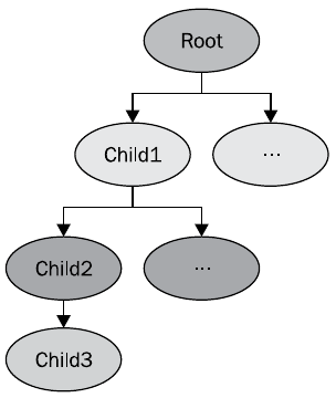
For example, for the scene shown in the figure, the following code
osg::NodePath &nodePath = child3->getParentalNodePaths()[0];
for (unsignedint i = 0; i < nodePath.size(); ++i)
{
	osg::Node *node = nodePath[i];
	// Что-нибудь делаем с нодой
}
returns the nodes Root, Child1, Child2.
You should not use memory management mechanisms to refer to parent nodes. When you delete the parent node, all the child nodes are automatically deleted, which may cause the application to crash.
3. Adding multiple models to the scene tree
We illustrate the mechanism for using groups with the following example.
The full text of the example group
main.h
main.cpp
#ifndef MAIN_H#define MAIN_H#include<osg/Group>#include<osgDB/ReadFile>#include<osgViewer/Viewer>#endifmain.cpp
#include"main.h"intmain(int argc, char *argv[]){
    (void) argc, (void) argv;
    osg::ref_ptr<osg::Node> model1 = osgDB::readNodeFile("../data/cessna.osg");
    osg::ref_ptr<osg::Node> model2 = osgDB::readNodeFile("../data/cow.osg");
    osg::ref_ptr<osg::Group> root = new osg::Group;
    root->addChild(model1.get());
    root->addChild(model2.get());
    osgViewer::Viewer viewer;
    viewer.setSceneData(root.get());
    return viewer.run();
}
Fundamentally, the example differs from all previous ones in that we load two three-dimensional models, and to add them to the scene we create a group root node and add our model cards to it as child nodes.
osg::ref_ptr<osg::Group> root = new osg::Group;
root->addChild(model1.get());
root->addChild(model2.get());
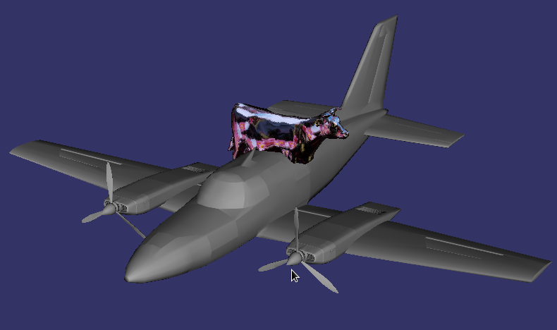
As a result, we get a scene consisting of two models - an airplane and a funny mirror cow. By the way, a mirror cow will not be a mirror, unless you copy its texture from OpenSceneGraph-Data / Images / reflect.rgb and the data / Images directory of our project.
The osg :: Group class can accept any type of node as a child, including nodes of its type. In contrast, the osg :: Geode class does not contain any child nodes at all - it is an end node containing the geometry of the scene object. This fact is useful when figuring out whether a node is a node of the osg :: Group type or another type derived from osg :: Node. Consider a small example.
osg::ref_ptr<osg::Group> model = dynamic_cast<osg::Group *>(osgDB::readNodeFile("../data/cessna.osg"));
The value returned by the osgDB :: readNodeFile () function is always of type osg :: Node *, but it can be converted to its successor osg :: Group *. If the node node of the Cessna model is a group node, then the conversion will be successful, otherwise the conversion will return NULL.
You can also do this trick that works on most compilers.
// Загружаем модель в групповой узел
osg::ref_ptr<osg::Group> group = ...;
// Преобразуем его к узлу
osg::Node* node1 = dynamic_cast<osg::Node*>( group.get() );
// Преобразуем группу к узлу неявно
osg::Node* node2 = group.get();
In performance-critical areas of the code, it is better to use special conversion methods.
osg::ref_ptr<osg::Node> model = osgDB::readNodeFile("cessna.osg");
osg::Group* convModel1 = model->asGroup(); // Работает нормально
osg::Geode* convModel2 = model->asGeode(); // Вернет NULL.
4. Transformation nodes
Nodes osg :: Group can not do any transformations, except the possibility of moving to their child nodes. OSG provides the osg :: Transform class for spatial displacement of geometry. This class is a successor of the osg :: Group class, but it is also abstract - in practice, its heirs are used instead, which implement various spatial transformations of geometry. When traversing a scene graph, the osg :: Transform node adds its own transformation to the current OpenGL transformation matrix. This is equivalent to multiplying the OpenGL transformation matrices, as executed by the glMultMatrix () command.
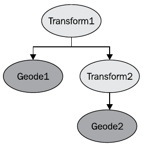
This example of a scene graph can be translated into the following OpenGL code
glPushMatrix();
	glMultMatrix( matrixOfTransform1 );
	renderGeode1();
	glPushMatrix();
		glMultMatrix( matrixOfTransform2 );
		renderGeode2();
	glPopMatrix();
glPopMatrix();
You can say that the position of the Geode1 is set in the coordinate system Transform1, and the position of the Geode2 is set in the coordinate system Transform2, shifted relative to Transform1. At the same time, in OSG, you can enable positioning in absolute coordinates, which will lead to an object's behavior equivalent to the result of the glGlobalMatrix () OpenGL command
transformNode->setReferenceFrame( osg::Transform::ABSOLUTE_RF );
You can switch back to positioning mode relative coordinates
transformNode->setReferenceFrame( osg::Transform::RELATIVE_RF );
5. The concept of the coordinate transformation matrix
The osg :: Matrix type is an OSG base type not managed by smart pointers. It provides an interface to 4x4 matrix operations that describe coordinate transformations, such as moving, rotating, scaling, and calculating projections. Matrix can be set explicitly
// Единичная матрица 4х4
osg::Matrix mat(1.0f, 0.0f, 0.0f, 0.0f,
		0.0f, 1.0f, 0.0f, 0.0f,
		0.0f, 0.0f, 1.0f, 0.0f,
		0.0f, 0.0f, 0.0f, 1.0f );
The osg :: Matrix class provides the following public methods:
- postMult () and operator * () - multiplication to the right of the current matrix by the matrix or vector, passed as a parameter. The preMult () method performs left multiplication.
- makeTranslate (), makeRotate () and makeScale () - reset the current matrix and create a 4x4 matrix describing the movement, rotation and scaling. their static versions translate (), rotate () and scale () can be used to create a matrix object with specific parameters.
- invert () - calculation of the inverse current matrix. Its static version of inverse () takes a matrix as a parameter and returns a new matrix, the inverse of the given one.
OSG understands matrices as row matrices, and vectors as rows, therefore, to apply a matrix transformation to a vector,
osg::Matrix mat = …;
osg::Vec3 vec = …;
osg::Vec3 resultVec = vec * mat;
The order of matrix operations is easy to understand by looking at how matrices are multiplied to produce an equivalent transformation.
osg::Matrix mat1 = osg::Matrix::scale(sx, sy, sz);
osg::Matrix mat2 = osg::Matrix::translate(x, y, z);
osg::Matrix resultMat = mat1 * mat2;
The developer should read the transformation process from left to right. That is, in the described code fragment, the vector is first scaled, and then it is moved.
osg :: Matrixf contains float elements.
6. Application class osg :: MatrixTransform
Let's apply the received theoretical knowledge in practice, having loaded two models of the plane in different points of a scene.
Full transform example text
main.h
main.cpp
#ifndef MAIN_H#define MAIN_H#include<osg/MatrixTransform>#include<osgDB/ReadFile>#include<osgViewer/Viewer>#endifmain.cpp
#include"main.h"intmain(int argc, char *argv[]){
    (void) argc; (void) argv;
    osg::ref_ptr<osg::Node> model = osgDB::readNodeFile("../data/cessna.osg");
    osg::ref_ptr<osg::MatrixTransform> transform1 = new osg::MatrixTransform;
    transform1->setMatrix(osg::Matrix::translate(-25.0, 0.0, 0.0));
    transform1->addChild(model.get());
    osg::ref_ptr<osg::MatrixTransform> transform2 = new osg::MatrixTransform;
    transform2->setMatrix(osg::Matrix::translate(25.0, 0.0, 0.0));
    transform2->addChild(model.get());
    osg::ref_ptr<osg::Group> root = new osg::Group;
    root->addChild(transform1.get());
    root->addChild(transform2.get());
    osgViewer::Viewer viewer;
    viewer.setSceneData(root.get());
    return viewer.run();
}
The example is actually quite trivial. We load model of the plane from a file
osg::ref_ptr<osg::Node> model = osgDB::readNodeFile("../data/cessna.osg");
Create a transformation node
osg::ref_ptr<osg::MatrixTransform> transform1 = new osg::MatrixTransform;
Set the transformation matrix as a transformation matrix along the X axis 25 units to the left.
transform1->setMatrix(osg::Matrix::translate(-25.0, 0.0, 0.0));
Set the transformation node for our model as a child node
transform1->addChild(model.get());
We do the same with the second transformation, but as the matrix we set the movement to the right by 25 units
osg::ref_ptr<osg::MatrixTransform> transform2 = new osg::MatrixTransform;
transform2->setMatrix(osg::Matrix::translate(25.0, 0.0, 0.0));
transform2->addChild(model.get());
Create a root node and set the transform1 and transform2 nodes as child nodes for it.
osg::ref_ptr<osg::Group> root = new osg::Group;
root->addChild(transform1.get());
root->addChild(transform2.get());
Create a viewer and pass the root node to it as scene data.
osgViewer::Viewer viewer;
viewer.setSceneData(root.get());
Running the program gives such a picture.
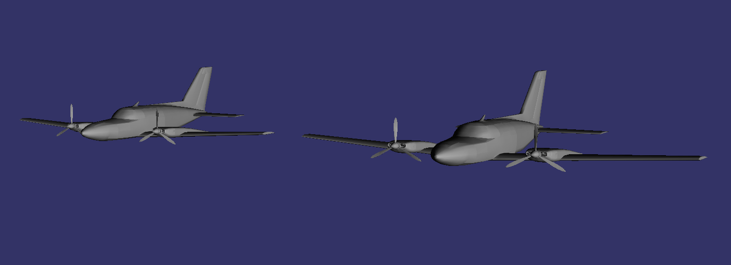
The structure of the scene graph in this example is as follows.
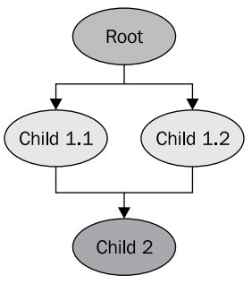
We should not be embarrassed by the fact that the transformation nodes (Child 1.1 and Child 1.2) refer to the same child model of the aircraft model (Child 2). This is a regular OSG mechanism, when one child node of a scene graph can have several parent nodes. Thus, it is not necessary for us to keep in memory two copies of the model in order to get two identical planes in the scene. Such a mechanism makes it very efficient to allocate memory in the application. The model will not be removed from memory as long as it is referred to as a child, at least one node.
By its action, the osg :: MatrixTransform class is equivalent to the OpenGL commands glMultMatrix () and glLoadMatrix (), it implements all types of spatial transformations, but is difficult to use because of the need to calculate the transformation matrix.
The osg :: PositionAttitudeTransform class works like OpenGL functions glTranslate (), glScale (), glRotate (). It provides public methods for converting child nodes:
- setPosition () - move a node to a given point in space, specified by the osg :: Vec3 parameter
- setScale () - scale the object along the axes. The scaling factors for the respective axes are set by the parameter of the type osg :: Vec3
- setAttitude () - set the spatial orientation of the object. As a parameter, it accepts the quaternion of the transformation of rotation osg :: Quat, the constructor of which has several overloads, allowing to set the quaternion both directly (componentwise) and, for example, through Euler angles osg :: Quat (xAngle, osg :: X_AXIS, yAngle, osg :: Y_AXIS, zAngle, osg :: Z_AXIS) (angles are given in radians!)
7. Switch nodes
Consider another class - osg :: Switch, which allows you to display or skip rendering of a scene node, depending on some logical condition. It is an inheritor of the osg :: Group class and attaches a logical value to each of its child nodes. It has several useful public methods:
- Overloaded addChild (), which as the second parameter accepts a logical key that indicates whether or not to display this node.
- setValue () - setting the visibility / invisibility key. Accepts the index of the child node we are interested in and the desired key value. Accordingly, getValue () allows you to get the current key value by the index of the node of interest.
- setNewChildDefaultValue () - sets the default value for the visibility key of all new objects added as children.
Consider the use of this class by example.
The full text of the example switch
main.h
main.cpp
#ifndef MAIN_H#define MAIN_H#include<osg/Switch>#include<osgDB/ReadFile>#include<osgViewer/Viewer>#endifmain.cpp
#include"main.h"intmain(int argc, char *argv[]){
    (void) argc; (void) argv;
    osg::ref_ptr<osg::Node> model1 = osgDB::readNodeFile("../data/cessna.osg");
    osg::ref_ptr<osg::Node> model2 = osgDB::readNodeFile("../data/cessnafire.osg");
    osg::ref_ptr<osg::Switch> root = new osg::Switch;
    root->addChild(model1.get(), false);
    root->addChild(model2.get(), true);
    osgViewer::Viewer viewer;
    viewer.setSceneData(root.get());
    return viewer.run();
}
An example is trivial - we load two models: the ordinary Cessna and the Cessna with the effect of a burning engine
osg::ref_ptr<osg::Node> model1 = osgDB::readNodeFile("../data/cessna.osg");
osg::ref_ptr<osg::Node> model2 = osgDB::readNodeFile("../data/cessnafire.osg");
However, we create osg :: Switch as the root node, which allows us, when adding models to it as child nodes, to set a visibility key for each of them.
osg::ref_ptr<osg::Switch> root = new osg::Switch;
root->addChild(model1.get(), false);
root->addChild(model2.get(), true);
That is, model1 will not be rendered, and model2 will be what we will observe by running the program.
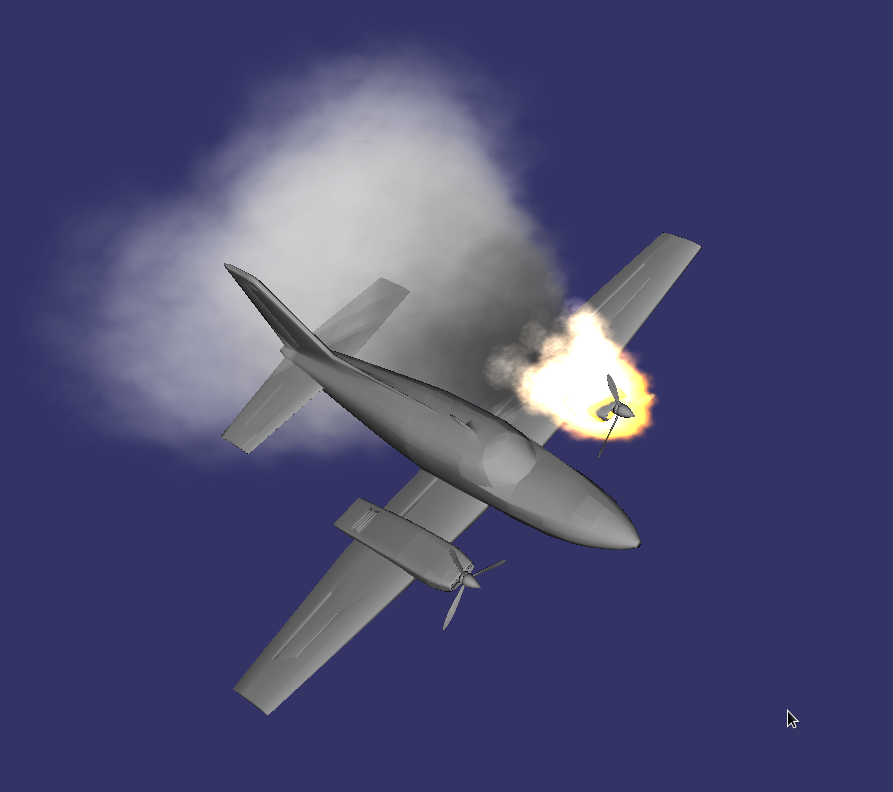
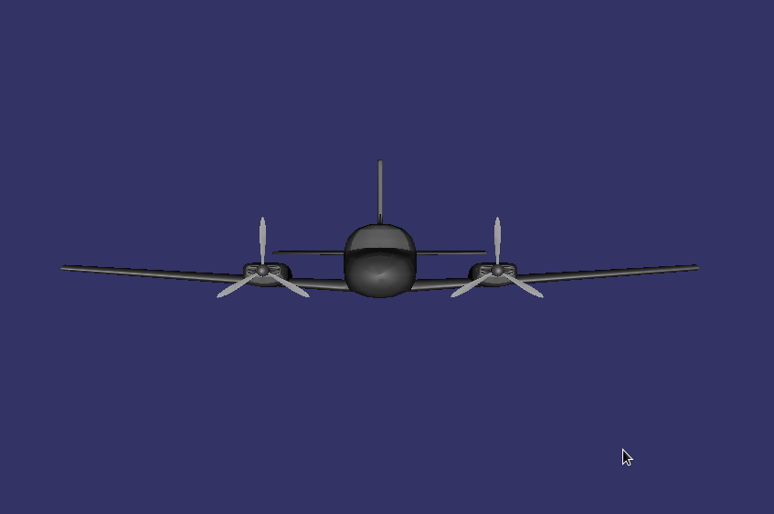
Swapping the key values will see the opposite picture.
root->addChild(model1.get(), true);
root->addChild(model2.get(), false);
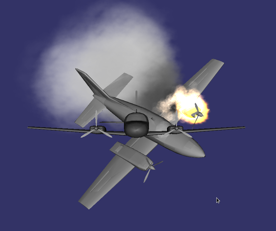
Having cocked both keys, we will see two models at the same time.
root->addChild(model1.get(), true);
root->addChild(model2.get(), true);
You can turn on the visibility and invisibility of the node that is a child of osg :: Switch right on the go, using the setValue () method
switchNode->setValue(0, false);
switchNode->setValue(0, true);
switchNode->setValue(1, true);
switchNode->setValue(1, false);
Conclusion
In this lesson, we covered all the main classes of intermediate nodes used in OpenSceeneGraph. Thus, we have laid another basic brick in the foundation of knowledge about the structure of this undoubtedly interesting graphic engine. The examples considered in the article, as before, are available in my repository on Github .
To be continued...
