Pseudo Lens Flare
Hi, Habr! I present to you the translation of the article “Pseudo Lens Flare” by John Chapman.
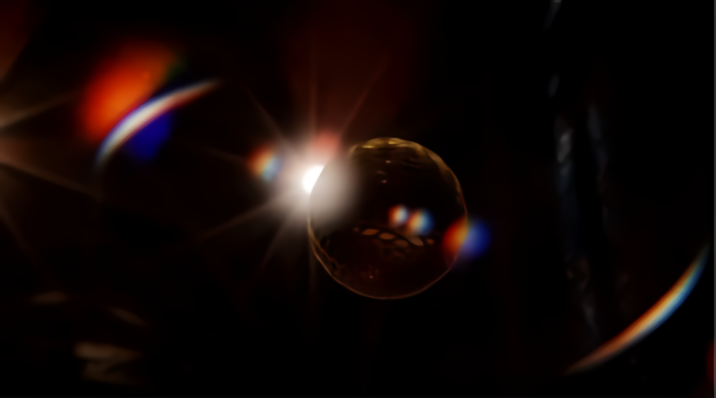
Lens flare (lens flare) is a photographic artifact that occurs when light is scattered and refracted in a lens system. Although it is an artifact, there are many reasons for using lens flare in computer graphics:
Traditionally, lens flare in realtime has been implemented using sprite-based technologies. Although sprites give easily controlled and very realistic results, they should be placed explicitly and require occlusion data for correct display. Here I will describe a simple and relatively cheap screen space effect that creates a pseudo lens flare from the input color buffer. It is not based on physics, so the result is slightly different from photorealistic, but it can be used in combination with (or as a substitute) for traditional sprite-based effects.
Consists of 4 stages:
Downsampling (reduced resolution) - optimization to reduce the cost of subsequent stages. In addition, we want to select a subset of the brightest pixels of the original image. Using scale / bias (scale / offset) provides a flexible way to achieve this:
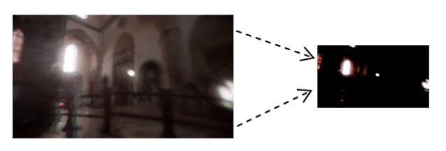
The scale / bias adjustment is the main way to adjust the effect; the best settings will depend on the dynamic range of the color buffer, as well as how thin you want to see the result. Due to the fact that the technique is an approximation, subtlety is more likely to look better.
Lens flare elements tend to rotate about the center of the image. By simulating this effect, we can expand the result of the previous stage horizontally / vertically. This is easy to do at the stage of generating elements, expanding the texture coordinates:
It is not necessary to do this; element generation works fine with this, and without it. However, the result of a change in texture coordinates helps to visually separate the lens flare effect from the original image.
“ Ghosts ” (ghosts) are repetitive highlights that reflect bright areas in the color buffer, turning around the center of the image. The approach I chose to generate is to get a vector from the current pixel to the center of the screen, and then make several samples along this vector.

Notice that I use fract () to ensure that the texture coordinates are wrapped around; equivalent you can use wrap mode GL_REPEAT for the texture .
Here is the result:
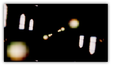
You can improve the result by allowing only bright areas closer to the center of the image to generate ghosts. We can achieve this by adding weights that will decrease from the center for samples:
The weight function is as simple as possible - linear. The reason why we calculate the weight inside the loop is that bright areas in the center of the input image can “cast” ghosts onto the borders, but bright areas on the borders cannot cast ghosts into the center.

The final improvement is a radial change in the color of the ghost, in accordance with the 1D texture:
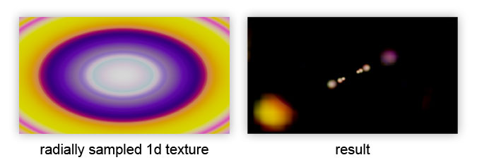
It is applied after the cycle to affect the final color of the ghost:
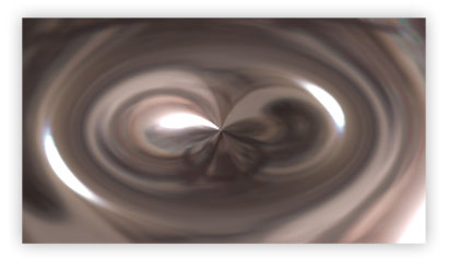
If we take the vector to the center of the image, as in the calculation of ghost , but fix the length of the vector, we will get another effect: the original image is deformed radially:
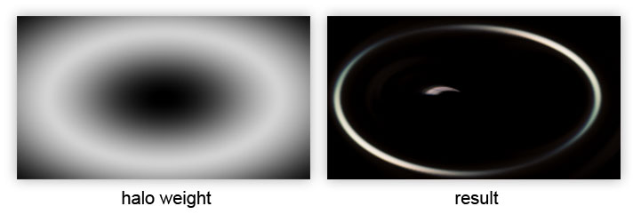
We can use this to create a “halo”, multiplying the weight by the sample, thus limiting the contribution deformed image ring, the radius of which is controlled by uHaloWidth :
Some glare on the lenses have color distortion caused by the variation of light refractions at different wavelengths. We can simulate this by creating a function that selects the red, green, and blue channels separately with slightly different offsets along the sample vector:
It can be used as a direct replacement for calling texture () in the previous listing. I calculate the direction and distortion as follows:
Although the sampling function is simple, it costs x3 texture samples, although they should all be cache-friendly, unless you specify a giant value for uDistortion .
With the generation of elements all. Here is the result:

Without blur, lens flare elements (in particular, ghosts), as a rule, preserve the appearance of the image. By adding blur to the lens flare elements , we weaken the high frequencies and thereby reduce the contrast with the input image, which helps us sell the effect.

I will not tell you how to make a blur; This can be read on various Internet resources (Gaussian blur).
So, we have our lens flare elements , well blurred. How can we combine them with the original original image? There are several important considerations regarding the entire render pipeline:
With this in mind, there are a couple of things that we can do at this stage to improve the result:
First, you need to modify the elements of lens flare using a “dirty” texture in full resolution (which is widely used in Battlefield 3):
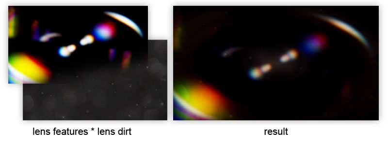
The key to this is the very texture of the dirt on the lenses. If the contrast is low, lens flare shapes tend to dominate the result. As the contrast increases, the lens flare elements are muffled, which gives a different aesthetic appearance and also hides some defects.
As an additional improvement, we can use a starburst texture by adding it to lens dirt :

In the form of a starburst texture, it does not look very good. However, we can transfer a transformation matrix to a shader, which will allow us to rotate / distort the starburst each frame and get the desired dynamic effect:
The uLensStarMatrix transformation matrix is based on the value obtained from the camera orientation as follows:
There are other ways to get the camrot value; most importantly, it should change continuously when you rotate the camera. The matrix itself is constructed as follows:
The scale and bias matrices need the offset of the origin of the texture coordinates so that we can rotate the starburst relative to the center of the image.
So now everything! This method demonstrates how a relatively simplified post process gives a decent looking lens flare . It is not exactly photorealistic, but if used correctly, it can give an excellent result.


Lens flare (lens flare) is a photographic artifact that occurs when light is scattered and refracted in a lens system. Although it is an artifact, there are many reasons for using lens flare in computer graphics:
- it increases the perceived brightness and visible dynamic range of the image.
- lens flare is often found in photographs, so its absence can be evident
- he may play an important role in style or drama, or may be part of the gameplay in games (imagine glare that blinds the player)
Traditionally, lens flare in realtime has been implemented using sprite-based technologies. Although sprites give easily controlled and very realistic results, they should be placed explicitly and require occlusion data for correct display. Here I will describe a simple and relatively cheap screen space effect that creates a pseudo lens flare from the input color buffer. It is not based on physics, so the result is slightly different from photorealistic, but it can be used in combination with (or as a substitute) for traditional sprite-based effects.
Algorithm
Consists of 4 stages:
- Downsample / threshold.
- Generation of elements flare .
- Blur.
- Upscale / blend with original image.
1. Downsample / Threshold
Downsampling (reduced resolution) - optimization to reduce the cost of subsequent stages. In addition, we want to select a subset of the brightest pixels of the original image. Using scale / bias (scale / offset) provides a flexible way to achieve this:
uniform sampler2D uInputTex;
uniform vec4 uScale;
uniform vec4 uBias;
noperspective in vec2 vTexcoord;
out vec4 fResult;
voidmain(){
      fResult = max(vec4(0.0), texture(uInputTex, vTexcoord) + uBias) * uScale;
}

The scale / bias adjustment is the main way to adjust the effect; the best settings will depend on the dynamic range of the color buffer, as well as how thin you want to see the result. Due to the fact that the technique is an approximation, subtlety is more likely to look better.
2. Generation of elements flare
Lens flare elements tend to rotate about the center of the image. By simulating this effect, we can expand the result of the previous stage horizontally / vertically. This is easy to do at the stage of generating elements, expanding the texture coordinates:
vec2 texcoord = -vTexcoords + vec2(1.0);
It is not necessary to do this; element generation works fine with this, and without it. However, the result of a change in texture coordinates helps to visually separate the lens flare effect from the original image.
Ghosts
“ Ghosts ” (ghosts) are repetitive highlights that reflect bright areas in the color buffer, turning around the center of the image. The approach I chose to generate is to get a vector from the current pixel to the center of the screen, and then make several samples along this vector.

uniform sampler2D uInputTex;
uniform int uGhosts; // number of ghost samples
uniform float uGhostDispersal; // dispersion factor
noperspective in vec2 vTexcoord;
out vec4 fResult;
voidmain(){
    vec2 texcoord = -vTexcoord + vec2(1.0);
    vec2 texelSize = 1.0 / vec2(textureSize(uInputTex, 0));
// ghost vector to image centre:
    vec2 ghostVec = (vec2(0.5) - texcoord) * uGhostDispersal;
// sample ghosts:
    vec4 result = vec4(0.0);
    for (int i = 0; i < uGhosts; ++i)
    {
        vec2 offset = fract(texcoord + ghostVec * float(i));
        result += texture(uInputTex, offset);
    }
    fResult = result;
}
Notice that I use fract () to ensure that the texture coordinates are wrapped around; equivalent you can use wrap mode GL_REPEAT for the texture .
Here is the result:

You can improve the result by allowing only bright areas closer to the center of the image to generate ghosts. We can achieve this by adding weights that will decrease from the center for samples:
vec4 result = vec4(0.0);
for (int i = 0; i < uGhosts; ++i)
{
    vec2 offset = fract(texcoord + ghostVec * float(i));
    float weight = length(vec2(0.5) - offset) / length(vec2(0.5));
    weight = pow(1.0 - weight, 10.0);
    result += texture(uInputTex, offset) * weight;
}
The weight function is as simple as possible - linear. The reason why we calculate the weight inside the loop is that bright areas in the center of the input image can “cast” ghosts onto the borders, but bright areas on the borders cannot cast ghosts into the center.

The final improvement is a radial change in the color of the ghost, in accordance with the 1D texture:

It is applied after the cycle to affect the final color of the ghost:
result *= texture(uLensColor, length(vec2(0.5) - texcoord) / length(vec2(0.5)));
HALOS (halos)
If we take the vector to the center of the image, as in the calculation of ghost , but fix the length of the vector, we will get another effect: the original image is deformed radially:

We can use this to create a “halo”, multiplying the weight by the sample, thus limiting the contribution deformed image ring, the radius of which is controlled by uHaloWidth :
// sample halo:
    vec2 haloVec = normalize(ghostVec) * uHaloWidth;
    float weight = length(vec2(0.5) - fract(texcoord + haloVec)) / length(vec2(0.5));
    weight = pow(1.0 - weight, 5.0);
    result += texture(uInputTex, texcoord + haloVec) * weight;

CHROMATIC DISTORTION (color distortion)
Some glare on the lenses have color distortion caused by the variation of light refractions at different wavelengths. We can simulate this by creating a function that selects the red, green, and blue channels separately with slightly different offsets along the sample vector:
vec3 textureDistorted(
    in sampler2D tex,
    in vec2 texcoord,
    in vec2 direction, // direction of distortion
    in vec3 distortion // per-channel distortion factor
){
    return vec3(
        texture(tex, texcoord + direction * distortion.r).r,
        texture(tex, texcoord + direction * distortion.g).g,
        texture(tex, texcoord + direction * distortion.b).b
    );
}
It can be used as a direct replacement for calling texture () in the previous listing. I calculate the direction and distortion as follows:
vec2 texelSize = 1.0 / vec2(textureSize(uInputTex, 0));
vec3 distortion = vec3(-texelSize.x * uDistortion, 0.0, texelSize.x * uDistortion);
vec3 direction = normalize(ghostVec);
Although the sampling function is simple, it costs x3 texture samples, although they should all be cache-friendly, unless you specify a giant value for uDistortion .
With the generation of elements all. Here is the result:

3. Blur
Without blur, lens flare elements (in particular, ghosts), as a rule, preserve the appearance of the image. By adding blur to the lens flare elements , we weaken the high frequencies and thereby reduce the contrast with the input image, which helps us sell the effect.

I will not tell you how to make a blur; This can be read on various Internet resources (Gaussian blur).
4. Upscale / blending with original image
So, we have our lens flare elements , well blurred. How can we combine them with the original original image? There are several important considerations regarding the entire render pipeline:
- Any subsequent motion blur or depth of field must be applied before combining with the lens flare , so the lens flare elements will not participate in these effects.
- Lens flare should be applied before any tonemapping . This has a physical meaning, since tonemapping simulates film / CMOS response to incoming light, of which lens flare is a part .
With this in mind, there are a couple of things that we can do at this stage to improve the result:
LENS DIRT
First, you need to modify the elements of lens flare using a “dirty” texture in full resolution (which is widely used in Battlefield 3):

uniform sampler2D uInputTex; // source image
uniform sampler2D uLensFlareTex; // input from the blur stage
uniform sampler2D uLensDirtTex; // full resolution dirt texture
noperspective in vec2 vTexcoord;
out vec4 fResult;
voidmain(){
    vec4 lensMod = texture(uLensDirtTex, vTexcoord);
    vec4 lensFlare = texture(uLensFlareTex, vTexcoord) * lensMod;
    fResult = texture(uInputTex, vTexcoord) + lensflare;
}
The key to this is the very texture of the dirt on the lenses. If the contrast is low, lens flare shapes tend to dominate the result. As the contrast increases, the lens flare elements are muffled, which gives a different aesthetic appearance and also hides some defects.
DIFFRACTION STARBURST
As an additional improvement, we can use a starburst texture by adding it to lens dirt :

In the form of a starburst texture, it does not look very good. However, we can transfer a transformation matrix to a shader, which will allow us to rotate / distort the starburst each frame and get the desired dynamic effect:
uniform sampler2D uInputTex; // source image
uniform sampler2D uLensFlareTex; // input from the blur stage
uniform sampler2D uLensDirtTex; // full resolution dirt texture
uniform sampler2D uLensStarTex; // diffraction starburst texture
uniform mat3 uLensStarMatrix; // transforms texcoords
noperspective in vec2 vTexcoord;
out vec4 fResult;
voidmain(){
    vec4 lensMod = texture(uLensDirtTex, vTexcoord);
    vec2 lensStarTexcoord = (uLensStarMatrix * vec3(vTexcoord, 1.0)).xy;
    lensMod += texture(uLensStarTex, lensStarTexcoord);
    vec4 lensFlare = texture(uLensFlareTex, vTexcoord) * lensMod;
    fResult = texture(uInputTex, vTexcoord) + lensflare;
}
The uLensStarMatrix transformation matrix is based on the value obtained from the camera orientation as follows:
vec3 camx = cam.getViewMatrix().col(0); // camera x (left) vector
vec3 camz = cam.getViewMatrix().col(1); // camera z (forward) vectorfloat camrot = dot(camx, vec3(0,0,1)) + dot(camz, vec3(0,1,0));
There are other ways to get the camrot value; most importantly, it should change continuously when you rotate the camera. The matrix itself is constructed as follows:
mat3 scaleBias1 = (
    2.0f,   0.0f,  -1.0f,
    0.0f,   2.0f,  -1.0f,
    0.0f,   0.0f,   1.0f,
);
mat3 rotation = (
    cos(camrot), -sin(camrot), 0.0f,
    sin(camrot), cos(camrot),  0.0f,
    0.0f,        0.0f,         1.0f
);
mat3 scaleBias2 = (
    0.5f,   0.0f,   0.5f,
    0.0f,   0.5f,   0.5f,
    0.0f,   0.0f,   1.0f,
);
mat3 uLensStarMatrix = scaleBias2 * rotation * scaleBias1;
The scale and bias matrices need the offset of the origin of the texture coordinates so that we can rotate the starburst relative to the center of the image.
Conclusion
So now everything! This method demonstrates how a relatively simplified post process gives a decent looking lens flare . It is not exactly photorealistic, but if used correctly, it can give an excellent result.

