Real-time mesh manipulation on Unity
- Transfer
One of the advantages of Unity as a platform for developing games is its powerful 3D engine. In this tutorial, you will learn about the world of 3D objects and mesh manipulation.
Due to the growth of virtual and augmented reality technology (VR / AR), most developers are faced with complex concepts of 3D graphics. Let this tutorial be their starting point. Do not worry, there will be no complicated 3D mathematics here - only hearts, pictures, arrows and a lot of interesting things!
Note: this tutorial is intended for users who are familiar with Unity's IDE and have some C # programming experience. If you do not have this knowledge, then study the tutorials Introduction to Unity UI and Introduction to Unity Scripting first .
You will need Unity version not lower than 2017.3.1. The latest version of Unity can be downloaded here . In this tutorial, the custom editor is used, for more information about them, see the tutorial Extending the Unity Editor .
Getting Started
To get started, familiarize yourself with the basic terms of 3D graphics, which will allow you to better understand the tutorial.
Basic technical terms for 3D graphics:
- Vertices : Each vertex is a point in the 3D space.
- Mesh : contains all vertices, edges, triangles, normals, and UV data of the model.
- Mesh Filter : Stores model mesh data.
- Mesh Renderer : Renders mesh data in the scene.
- Normals : A vertex or surface vector. It is directed outward, perpendicular to the surface of the mesh.
- Lines / Edges : invisible lines connecting vertices to each other.
- Triangles : formed by connecting three vertices.
- UV-Scan (UV Map) : binds the material to an object, creating texture and color for it.
The anatomy of a 3D object begins with its mesh. The creation of this mesh starts from its vertices. The invisible lines connecting these vertices form triangles that define the basic shape of the object.
Then the normals and the UV data define shading, color, and texture. The mesh data is stored in the mesh filter, and the mesh renderer uses this data to draw the object in the scene.
That is, the pseudo-code for creating a 3D model looks like this:
- Create a new mesh called myMesh.
- Add data to the properties of vertices and triangles myMesh.
- Create a new mesh filter called myMeshFilter.
- Set the myMeshFilter mesh property to myMesh.
Having dealt with the basics, download the project , unzip the files and run the project blank in Unity. Look at the folder structure in the Project window :
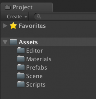
Folder Description:
- Prefabs : contains the Sphere prefab, which will be used to save the 3D mesh during the execution of the application.
- Scenes : contains three scenes that we use in this tutorial.
- Editor : The scripts inside this folder give us in the editor super powers that we use in development.
- Scripts : here are the runtime scripts that are attached to the GameObject and run when you click on Play .
- Materials : this folder contains material for the mesh.
In the next section, we will create a custom editor to visualize the creation of a 3D mesh.
Modifying meshes using Custom Editor
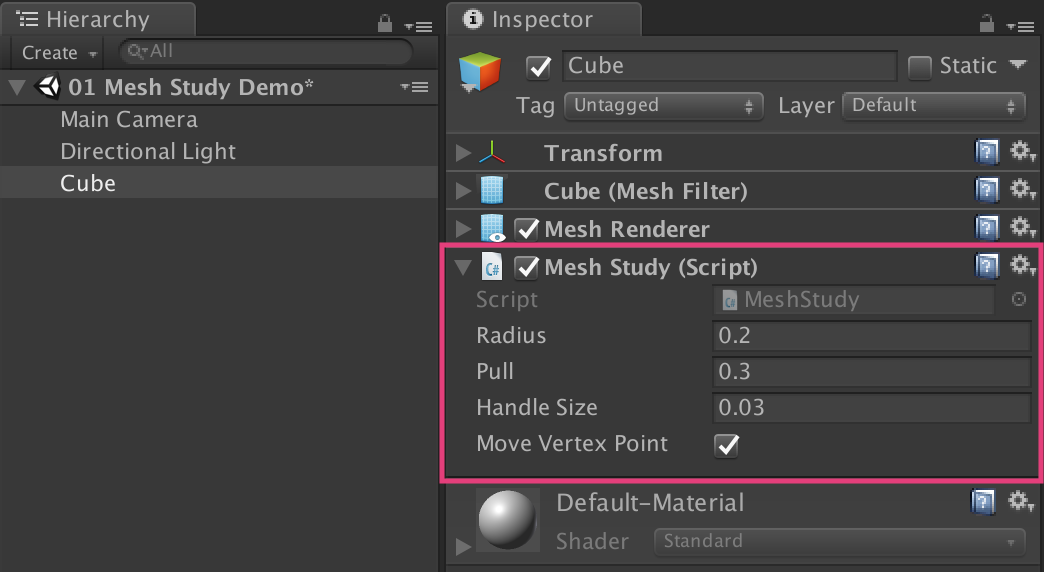
Open the 01 Mesh Study Demo , located in the Scenes folder . In the Scene window, you will see a 3D cube:
Before we start the mesh, let's take a look at the custom editor script.
Change editor script
Select the Editor folder in the Project window . The scripts in this folder add functionality to the editor (Editor) during development and are not available in Build mode.

Open MeshInspector.cs and view the source code. All Editor scripts must implement a class
Editor, its attribute CustomEditortells the class Editorfor which type of object it is an editor. OnSceneGUI()- this is an event method that allows drawing in the Scene window; OnInspectorGUI()allows you to add additional GUI elements to the Inspector. In MeshInspector.cs, before the beginning of the class,
MeshInspectoradd the following:[CustomEditor(typeof(MeshStudy))]Code Explanation: The attribute
CustomEditortells Unity which type of object the custom editor class can modify. As
OnSceneGUI()before EditMesh(), add:mesh = target as MeshStudy;
Debug.Log("Custom editor is running");Code Explanation: The class
Editorhas a standard variable target. Here targetis the conversion to MeshStudy. Now the custom editor will draw all the GameObject and MeshStudy.cs attached to it in the Scene window . Adding debug messages allows you to verify in the console that the custom editor is actually running. Preserve ( the Save ) the file and return to Unity. Go to the Scripts folder and drag the MeshStudy.cs onto the GameObject Cube in the Hierarchy to attach it.
Now the message “Custom editor is running” should be displayed in the console, and this means that we did everything right! You can delete the debug message so that it does not interfere with us in the console.
Clone and reset a mesh
When working with a 3D mesh in Edit mode using the custom editor, be careful not to overwrite the default Unity mesh. If this happens, you have to restart Unity.
To safely clone a mesh without overwriting the original form, create a copy of the mesh from the property
MeshFilter.sharedmeshand assign it again to the mesh filter. To do this, double-click MeshStudy.cs in the Scripts folder to open the file in the code editor. This script inherits from the class
MonoBehaviour, and its function is Start()not executed in Edit mode. In MeshStudy.cs before the class
MeshStudyto add the following:[ExecuteInEditMode]Explanation of the code: after adding this attribute, the function
Start()will be executed both in the Play mode and in the Edit mode. Now we can first create an instance of the mesh object and clone it. Add the
InitMesh()following code:oMeshFilter = GetComponent<MeshFilter>();
oMesh = oMeshFilter.sharedMesh; //1
cMesh = new Mesh(); //2
cMesh.name = "clone";
cMesh.vertices = oMesh.vertices;
cMesh.triangles = oMesh.triangles;
cMesh.normals = oMesh.normals;
cMesh.uv = oMesh.uv;
oMeshFilter.mesh = cMesh; //3
vertices = cMesh.vertices; //4
triangles = cMesh.triangles;
isCloned = true;
Debug.Log("Init & Cloned");Explanation of the code:
- Gets the source mesh
oMeshfrom the componentMeshFilter. - Copies to a new instance of the mesh
cMesh. - Assigns the copied mesh to the mesh filter again.
- Updates local variables.
Save the file and return to Unity. The message “Init & Cloned” should be displayed in the debug console. Select the GameObject
Cubein the Hierarchy and check its properties in the Inspector . The Mesh Filter should be displayed Asset mesh called the clone . Fine! This means that we have successfully cloned the mesh.
In the Editor folder, go to MeshInspector.cs . In
OnInspectorGUI(), after the second line of code, add the following:if (GUILayout.Button("Reset")) //1
{
mesh.Reset(); //2
}Explanation of the code:
- This code draws the Reset button in the Inspector .
- When clicked, it calls a function in MeshStudy.cs
Reset().
Save the file, open MeshStudy.cs and add the
Reset()following code to the function :if (cMesh != null && oMesh != null) //1
{
cMesh.vertices = oMesh.vertices; //2
cMesh.triangles = oMesh.triangles;
cMesh.normals = oMesh.normals;
cMesh.uv = oMesh.uv;
oMeshFilter.mesh = cMesh; //3
vertices = cMesh.vertices; //4
triangles = cMesh.triangles;
}Explanation of the code:
- Check for the existence of the original and cloned mesh.
- Reset
cMeshto source mesh. - Assignment
cMeshoMeshFilter. - Update local variables.
Save the file and return to Unity. In the Inspector, click on the Test Edit button to distort the cube mesh. Next, click the Reset button ; the cube should return to the original form.
Explaining vertices and triangles in Unity
A mesh consists of vertices connected by edges to triangles. Triangles define the basic shape of an object.
Mesh class:
- Vertices are stored as an array of values
Vector3.- Triangles are stored as an array of integer corresponding to the indices of the array of vertices.
That is, in a simple Quad mesh, consisting of four vertices and two triangles, the mesh data will look like this:
Vertex mapping
Here we want to display the vertices of the cube as blue dots.
In MeshInspector.cs, let's go into the function
EditMesh()and add the following:handleTransform = mesh.transform; //1
handleRotation = Tools.pivotRotation == PivotRotation.Local ? handleTransform.rotation : Quaternion.identity; //2for (int i = 0; i < mesh.vertices.Length; i++) //3
{
ShowPoint(i);
}Explanation of the code:
handleTransformgets from themeshvalue of the transform.handleRotationgets the current hinge Rotation mode.- Go around the vertices of the mesh and draw the points with
ShowPoint().
In the function
ShowPoint(), immediately after the comment, //draw dotadd the following:Vector3 point = handleTransform.TransformPoint(mesh.vertices[index]);Explanation of the code: this string converts the local position of the vertex into a coordinate in world space.
In the same function, in the block
ifimmediately after the newly added line of code, add the following:Handles.color = Color.blue;
point = Handles.FreeMoveHandle(point, handleRotation, mesh.handleSize, Vector3.zero, Handles.DotHandleCap);Explanation of the code:
- Sets the color, size, and position of a point using an auxiliary class
Handles. Handles.FreeMoveHandle()creates an unrestricted motion manipulator that simplifies the drag and drop operation, which will come in handy in the next section.
Save the file and return to Unity. Check the cube property in the Inspector and make sure the Move Vertex Point option is on. You should now see that the mesh on the screen is marked with a few blue dots. Here they are - the tops of the cube mesh! Try doing this with other 3D objects and observe the results.

Move a single vertex
Let's start with the simplest step of manipulating the mesh - moving a single vertex.
Navigate to MeshInspector.cs . Inside the function
ShowPoint(), immediately after the comment //dragand right before the block closing brackets ifadd the following:if (GUI.changed) //1
{
mesh.DoAction(index, handleTransform.InverseTransformPoint(point)); //2
}Explanation of the code:
GUI.changedkeeps track of all changes that occur with points, and works well withHandles.FreeMoveHandle()to recognize the drag and drop operation.- For a dragged vertex, the function
mesh.DoAction()gets its index and Transform values as parameters. Since the Transform vertex values are in world space, we transform them into local space withInverseTransformPoint().
Save the script file and go to MeshStudy.cs . In
DoAction(), after the opening brackets add the following:PullOneVertex(index, localPos);Then add the
PullOneVertex()following to the function :vertices[index] = newPos; //1
cMesh.vertices = vertices; //2
cMesh.RecalculateNormals(); //3Explanation of the code:
- We update the target vertex value
newPos. - Assign the values of the updated vertices back
cMesh.vertices. - In
RecalculateNormals()recalculate and redraw the mesh to match the changes.
Save the file and return to Unity. Try dragging points on a cube; Did you see a broken mesh?

It seems that some of the vertices have the same position, so when we drag only one, the other vertices remain behind it, and the mesh breaks. In the next section, we will fix this problem.
Finding all similar vertices
Visually, the cube mesh consists of eight vertices, six sides and 12 triangles. Let's check it out.
Open MeshStudy.cs , take a look at the place in front of the function
Start()and find the variable vertices. We will see the following:[HideInInspector]
public Vector3[] vertices;Code Explanation:
[HideInInspector]Hides the shared variable from the Inspector window . Comment out this attribute:
//[HideInInspector]public Vector3[] vertices;Note: Hiding the vertex values helps [HideInInspector]in case of more complex 3D meshes. Since the size of the array of vertices can reach thousands of elements, this can lead to Unity inhibition when trying to view the value of the array in the Inspector.Save the file and return to Unity. Go to the Inspector . Now the vertices property has appeared under the Mesh Study script component . Click the arrow icon next to it; so you expand the array of elements .
Vector3
You can see that the size of the array is 24, that is, there are vertices that have the same position! Before you continue, do not forget to uncomment
[HideInInspector].Why is vertex 24?
На этот счёт есть много теорий. Но простейший ответ таков: у куба шесть сторон, и каждая сторона составлена из четырёх вершин, образующих плоскость.
Поэтому расчёт таков: 6 x 4 = 24 вершины.
Можете поискать и другие ответы. Но пока достаточно просто знать, что у некоторых мешей будут вершины, имеющие одинаковую позицию.
Поэтому расчёт таков: 6 x 4 = 24 вершины.
Можете поискать и другие ответы. Но пока достаточно просто знать, что у некоторых мешей будут вершины, имеющие одинаковую позицию.
In MeshStudy.cs, replace all the code inside the function
DoAction()with the following:PullSimilarVertices(index, localPos);Go to the function
PullSimilarVertices()and add the following:Vector3 targetVertexPos = vertices[index]; //1
List<int> relatedVertices = FindRelatedVertices(targetVertexPos, false); //2foreach (int i in relatedVertices) //3
{
vertices[i] = newPos;
}
cMesh.vertices = vertices; //4
cMesh.RecalculateNormals();Explanation of the code:
- get the position of the target vertex, which will be used as the argument of the method
FindRelatedVertices(). - This method returns a list of indexes (corresponding to vertices) that have the same position as the target vertex.
- The loop traverses the entire list and assigns a value to the corresponding vertices
newPos. - We assign the updated
verticesbackcMesh.vertices. Then we callRecalculateNormals()to redraw the mesh with the new values.
Save the file and return to Unity. Drag any of the vertices; now the mesh must retain its shape and not collapse.
Now that we have completed the first step in manipulating the meshes, save the scene and move on to the next section.
Manipulating Meshes
In this section, you will learn about real-time mesh manipulation. There are many ways, but in this tutorial we will look at the most simple type of manipulation of meshes, namely the movement of previously created mesh vertices.
Collect selected indexes
We start by selecting the vertices that we will move in real time.
Open Scene 02 Create Heart Mesh from the Scenes folder . In the Scene window, you will see a red sphere. Select Sphere in the Hierarchy and go to the Inspector . You'll see that the Heart Mesh script component is attached to the object .
Now we need the Editor script for this object to display the vertices of the mesh in the Scene window. Go to the Editor folder and double-click on HeartMeshInspector.cs .
In the function
ShowHandle(), inside the block ifadd the following:Handles.color = Color.blue;
if (Handles.Button(point, handleRotation, mesh.pickSize, mesh.pickSize, Handles.DotHandleCap)) //1
{
mesh.selectedIndices.Add(index); //2
}Explanation of the code:
- Sets and displays the vertices of the mesh as a type
Handles.Button. - When pressed, he adds the selected index in the pressed list
mesh.selectedIndices.
In
OnInspectorGUI(), before the closing bracket, add the following:if (GUILayout.Button("Clear Selected Vertices"))
{
mesh.ClearAllData();
}Explanation of the code: this is how we add the Reset button to the call in the Inspector
mesh.ClearAllData() . Save the file and open HeartMesh.cs from the Scripts folder .
ClearAllData()Add the following to the function :selectedIndices = new List<int>();
targetIndex = 0;
targetVertex = Vector3.zero;Code Explanation: Code clears values in
selectedIndicesand targetIndex. It also resets targetVertex. Save the file and return to Unity. Select Sphere and go to the Inspector component of the HeartMesh script . Expand Selected Indices by clicking on the arrow icon next to it. This will allow us to track every vertex added to the list.
Enable Is Edit Mode using the checkbox next to it. Due to this, the mesh vertices will be drawn in the Scene window. When clicking on the blue dots in Selected Indices , the values should change accordingly. Also test the Clear Selected Vertices button.to make sure it clears all values.
Note: in the modified custom Inspector we have an option to show / hide the transform manipulator using the Show Transform Handle . So do not panic if you do not find the Transform manipulator in other scenes! Turn it on before quitting.
Turning a sphere into a heart
Changing the vertices of the mesh in real time essentially consists of three stages:
- Copy the current vertices of the mesh (before the animation) in
mVertices. - Perform calculations and change values in
mVertices. - Update the current vertices of the mesh with help
mVerticeswhen changing at each stage and let Unity automatically calculate the normals.
Open HeartMesh.cs and the
Start()following variables before the function :publicfloat radiusofeffect = 0.3f; //1 publicfloat pullvalue = 0.3f; //2publicfloat duration = 1.2f; //3int currentIndex = 0; //4bool isAnimate = false;
float starttime = 0f;
float runtime = 0f; Explanation of the code:
- The radius of the area affected by the target vertex.
- Dragging Force.
- The duration of the animation.
- The current index of the list
selectedIndices.
In the function
Init()before the block, ifadd the following:currentIndex = 0; The explanation of the code: at the beginning of the game is
currentIndexassigned the value 0 - the first index of the list selectedIndices. In the same function, add the following
Init()before the closing bracket of the block else:StartDisplacement();Explanation of the code: we start the function
StartDisplacement()if isEditModeit is false. Inside the function,
StartDisplacement()add the following:targetVertex = oVertices[selectedIndices[currentIndex]]; //1
starttime = Time.time; //2
isAnimate = true;Explanation of the code:
- Select
targetVertexto start the animation. - Set the start time and change the value
isAnimateto true.
After the function,
StartDisplacement()create a function FixedUpdate()with the following code:voidFixedUpdate() //1
{
if (!isAnimate) //2
{
return;
}
runtime = Time.time - starttime; //3if (runtime < duration) //4
{
Vector3 targetVertexPos = oFilter.transform.InverseTransformPoint(targetVertex);
DisplaceVertices(targetVertexPos, pullvalue, radiusofeffect);
}
else//5
{
currentIndex++;
if (currentIndex < selectedIndices.Count) //6
{
StartDisplacement();
}
else//7
{
oMesh = GetComponent<MeshFilter>().mesh;
isAnimate = false;
isMeshReady = true;
}
}
}Explanation of the code:
- The function
FixedUpdate()is performed in a loop with a fixed FPS. - If
isAnimatefalse, then skip the following code. - Change the
runtimeanimation. - If it
runtimeis withinduration, then we get the world coordinatestargetVertexandDisplaceVertices(), covering the target vertex with the parameterspullvalueandradiusofeffect. - Otherwise, time is over. We add to the
currentIndexunit. - Check whether is
currentIndexamongselectedIndices. Go to the next vertex in the list withStartDisplacement(). - Otherwise, at the end of the list, change the data
oMeshto the current mesh and set theisAnimatevalue to false to stop the animation.
Add the
DisplaceVertices()following:Vector3 currentVertexPos = Vector3.zero;
float sqrRadius = radius * radius; //1for (int i = 0; i < mVertices.Length; i++) //2
{
currentVertexPos = mVertices[i];
float sqrMagnitute = (currentVertexPos - targetVertexPos).sqrMagnitude; //3if (sqrMagnitute > sqrRadius)
{
continue; //4
}
float distance = Mathf.Sqrt(sqrMagnitute); //5float falloff = GaussFalloff(distance, radius);
Vector3 translate = (currentVertexPos * force) * falloff; //6
translate.z = 0f;
Quaternion rotation = Quaternion.Euler(translate);
Matrix4x4 m = Matrix4x4.TRS(translate, rotation, Vector3.one);
mVertices[i] = m.MultiplyPoint3x4(currentVertexPos);
}
oMesh.vertices = mVertices; //7
oMesh.RecalculateNormals();Explanation of the code:
- Square radius.
- We loop around each vertex of the mesh.
- Get
sqrMagnitudebetweencurrentVertexPosandtargetVertexPos. - If it
sqrMagnitudeexceedssqrRadius, then go to the next vertex. - Otherwise, continue by defining a value
falloffthat depends on the distance of thedistancecurrent vertex from the center point of the action area. - We get a new position
Vector3and apply its Transform to the current vertex. - At an exit from a cycle we assign to these
oMeshchanged valuesmVertices, and we force Unity to recalculate normals.
Source of the Falloff technique
The original formula is taken from the Procedural Examples asset package file , which can be downloaded for free from the Unity Asset Store.
Save the file and return to Unity. Select Sphere , go to the HeartMesh component and try adding a few vertices to the Selected Indices property . Disable Is Edit mode and click Play to view the result of your work.

Experiment with the Radiusofeffect , Pullvalue, and Duration values to get different results. When you are ready, change the settings according to the screenshot below.

Click on Play . Has your sphere turned into a heart?
Congratulations! In the next section, we will save the mesh to a prefab for future use.
Saving the mesh in real time
To save the procedural mesh in the shape of a heart in Play mode, you need to prepare a prefab, a child of which will be a 3D object, and then replace it with a new mesh asset with a script.
In the Project window , find the CustomHeart in the Prefabs folder . Click the arrow icon to expand its contents and select Child . Now you see the Sphere object in the Inspector preview window . This is the prefab that will store the new mesh data.

Open HeartMeshInspector.cs . Inside the function
OnInspectorGUI(), add the following before the closing bracket:if (!mesh.isEditMode && mesh.isMeshReady)
{
string path = "Assets/Prefabs/CustomHeart.prefab"; //1if (GUILayout.Button("Save Mesh"))
{
mesh.isMeshReady = false;
Object pfObj = AssetDatabase.LoadAssetAtPath(path, typeof(GameObject)); //2
Object pfRef = AssetDatabase.LoadAssetAtPath (path, typeof(GameObject));
GameObject gameObj = (GameObject)PrefabUtility.InstantiatePrefab(pfObj);
Mesh pfMesh = (Mesh)AssetDatabase.LoadAssetAtPath(path, typeof(Mesh)); //3if (!pfMesh)
{
pfMesh = new Mesh();
}
else
{
pfMesh.Clear();
}
pfMesh = mesh.SaveMesh(); //4
AssetDatabase.AddObjectToAsset(pfMesh, path);
gameObj.GetComponentInChildren<MeshFilter>().mesh = pfMesh; //5
PrefabUtility.ReplacePrefab(gameObj, pfRef, ReplacePrefabOptions.Default); //6
Object.DestroyImmediate(gameObj); //7
}
}Explanation of the code:
- Sets the
pathvalue of the path to the CustomHeart prefab object . - Creates two objects from the CustomHeart prefab , one to create an instance as GameObject (
pfObj), the second as links (pfRef). - Creates an instance of the mesh mesh from CustomHeart
pfMesh. If not found, creates a new mesh, otherwise clears the existing data. - Fills
pfMeshwith new mesh data, and then adds it as an asset to CustomHeart . - Fills the mesh asset in
gameObjvaluepfMesh. - Replaces CustomHeart by
gameObjjuxtaposing pre-existing connections. - Instantly destroys
gameObj.
Save the file and go to HeartMesh.cs . In the general method
SaveMesh(), after creating an instance, nMeshadd the following:nMesh.name = "HeartMesh";
nMesh.vertices = oMesh.vertices;
nMesh.triangles = oMesh.triangles;
nMesh.normals = oMesh.normals;Explanation of the code: returns an asset of the mesh with values from the heart-shaped mesh.
Save the file and return to Unity. Click play . When the animation is complete, the Save Mesh button will appear in the Inspector . Click the button to save the new mesh, and then stop the player. Go to the Prefabs folder and look at the CustomHeart prefab . You should see that now in the CustomHeart prefab object there is a completely new heart-shaped mesh.

Great job!
We put everything together
In the previous scene, the function
DisplaceVertices()used the Falloff formula to determine the drag force that was applied to each vertex within the specified radius. The “fall off” point at which the drag force begins to decrease depends on the type of falloff used: Linear, Gaussian, or Needle. Each type creates different results in the mesh.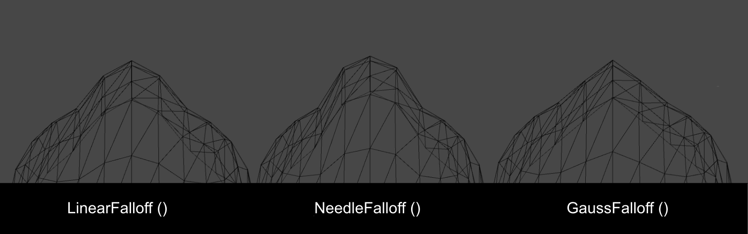
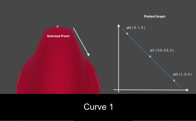
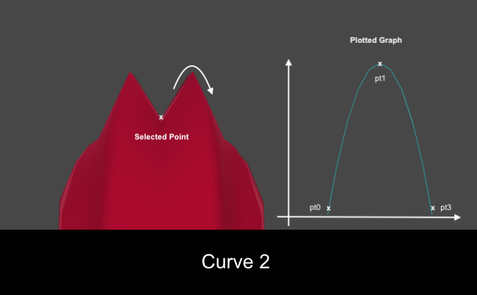
In this section, we will look at another way of manipulating vertices: using a given curve. Taking the rule that the speed is equal to the distance divided by time (d = (v / t)), we can determine the position of the vector, referring to its distance divided by time.
Using the curve method
Save the current scene and open 03 Customize Heart Mesh from the Scenes folder . You will see in the Hierarchy an instance of the CustomHeart prefab . Click the arrow icon next to it to expand its contents and select Child .
View its properties in the Inspector . You will see the Mesh Filter component with the Heart Mesh asset . Attach the Custom Heart script to Child as a component . Now the asset should change from HeartMesh to clone .
Next, open CustomHeart.cs from the Scripts folder .
Start()Add the following before the function :publicenum CurveType
{
Curve1, Curve2
}
public CurveType curveType;
Curve curve;Explanation of the code: here a generic enumeration (enum) is created under the name
CurveType, after which it is made available from the Inspector . Go to
CurveType1()and add the following:Vector3[] curvepoints = new Vector3[3]; //1
curvepoints[0] = new Vector3(0, 1, 0);
curvepoints[1] = new Vector3(0.5f, 0.5f, 0);
curvepoints[2] = new Vector3(1, 0, 0);
curve = new Curve(curvepoints[0], curvepoints[1], curvepoints[2], false); //2Explanation of the code:
- A simple curve consists of three points. Set the points for the first curve.
- We generate the first curve with the help
Curve()and we assign its valuescurve. The drawn curve can be displayed in the preview, if the last parameter is true.
Go to
CurveType2()and add the following:Vector3[] curvepoints = new Vector3[3]; //1
curvepoints[0] = new Vector3(0, 0, 0);
curvepoints[1] = new Vector3(0.5f, 1, 0);
curvepoints[2] = new Vector3(1, 0, 0);
curve = new Curve(curvepoints[0], curvepoints[1], curvepoints[2], false); //2Explanation of the code:
- Set the points for the second curve.
- Generate the second curve with
Curve()and assign its valuescurve. The drawn curve can be displayed in the preview, if the last parameter is true.
B
StartDisplacement(), before the closing bracket add the following:if (curveType == CurveType.Curve1)
{
CurveType1();
}
elseif (curveType == CurveType.Curve2)
{
CurveType2();
}Explanation of the code: here we check the option selected by the user
curveTypeand generate it accordingly curve. B
DisplaceVertices(), inside the cycle operator, forbefore the closing brackets add the following:float increment = curve.GetPoint(distance).y * force; //1
Vector3 translate = (vert * increment) * Time.deltaTime; //2
Quaternion rotation = Quaternion.Euler(translate);
Matrix4x4 m = Matrix4x4.TRS(translate, rotation, Vector3.one);
mVertices[i] = m.MultiplyPoint3x4(mVertices[i]);Explanation of the code:
- We get the position of the curve on the given one
distanceand multiply its valueybyforceto getincrement. - Create a new data type
Vector3to store the new position of the current vertex and apply its Transform accordingly.
Save the file and return to Unity. Check the properties of the component CustomHeart game object Child . You will see a drop-down list where you can select the Curve Type . In the Edit Type drop-down list, select Add Indices or Remove Indices to update the list of vertices and experiment with different settings.
To see detailed results for different types of curves, enter values according to the screenshot:
For the Curve Type list, select the Curve1 value , make sure that None is selected for the Edit Type and click Play . You should see the mesh diverge into the pattern. Twist the model to see it in the side view, and compare the results for both types of curves. Here you can see how the selected Curve Type affects the mesh offset.
That's all! You can click on Clear Selected Vertices to reset the Selected Indices and experiment with your own patterns. But do not forget that there are other factors that will affect the final result of the mesh, namely:
- Radius value.
- The distribution of vertices in the region.
- The position of the pattern of the selected vertices.
- The method chosen for the offset.
Where to go next?
Files of the finished project are in the archive of the project tutorial.
Do not stop at this! Try to use more sophisticated techniques used in the tutorial "Procedural generation of mazes in Unity" .
I hope you liked this tutorial, and the information was useful. Special thanks go to Jasper Flick from Catlike Coding for his great tutorials that helped me build a demo for my project.
