Step by step: Broadcast data to flightradar24
1. Introduction
My current activity has nothing to do with aviation, but it so happened that I got sick with it. At what exact moment this happened - it's hard to say, probably, the first flight greatly contributed to this. After some time, I began to watch films on aviation subjects, to be interested in the structure and differences in airplanes, and to look for how to connect my activities at least a little with my hobby. So I got acquainted with ADS-B technology and its unexpected application among enthusiasts - radarspotting. On open spaces of Habr not often articles on this subject appear ( one , two ). Therefore, here I want to talk a little about the topic of radar spotting and describe in detail the process of creating an independent broadcast of data to the popular resource flightradar24 .
So, for everyone who is interested (sick) in the topic of aviation and aircraft observation, and also wants to take their direct part in this, welcome to cat.
2. What is radarspotting
Radarspotting is one of the varieties of spotting (from the word spot - to observe), a type of hobby in which aircraft are monitored using special receivers and software that allows you to process data received from aircraft and presents them in a form convenient for the observer. Radarspoting is based on ADS-B technology, with the help of which, from an aircraft equipped with an ADS-B transponder, it is possible to obtain parameters such as the ICAO address of the aircraft, its location coordinates, course, altitude, horizontal and vertical speed.
Usually, the whole software package consists of two parts:
- Software for receiving and decoding data ( ADSBScope , Basestation , dump1090 , etc.);
- Software for visual display (transmission) of received data ( Virtual Radar Server , PlanePlotter , etc.).
The choice of specific software depends primarily on the type of receiver and the task. For example, if you have a microADSB receiver and you want to see which flights are within the range of your antenna, you can use the ADSBScope + PlanePlotter bundle .
But in this case, you can only observe the local area, the boundaries of which are set by the antenna connected to the receiver. It seems to me that it is much more interesting to observe a large-scale picture, the data of which flow from tens of thousands of devices (including yours) located all over the globe.
So we smoothly approached the heading - to organize our own data transmission to one of these services, while not resorting to large financial costs.
3. Material base
To build your own data center, you must:
- ADS-B receiver (receiver);
- Antenna at 1090 MHz;
- Connection cable;
- A computer, or other device (which, we will consider later);
- Software suite;
- Permanent Internet access.
3.1 ADS-B receiver
At the initial stage, a USB DVB-T receiver based on the RTL2832 chipset is perfect for these purposes . Such a device can be ordered on the same Ebay for a symbolic $ 7-9 .
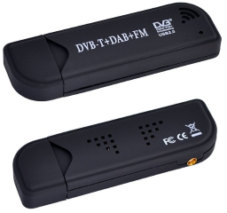
Read more about the operation of this device here . If you want to use something more seriously, then a rather large number of different ADS-B receivers are listed here .
3.2 Receive antenna at 1090 MHz
Here everything is much more complicated. Because the signal coming from the ADS-B transponder is very weak, it is desirable to have a dipole antenna mounted vertically upward with an element length of 69 mm . A lot will depend on the type of design and manufacturing accuracy of this device.
There are both home-made and industrial versions of antennas on sale , but the price of both options for the entry-level leaves much to be desired.
With self-made antennas, you can pay attention to options such as the Franklin antenna , or vertical collinear. I refused the Franklin antenna due to the fact that when manufacturing at home (in haste) it is almost impossible to maintain the exact geometric dimensions.
It is necessary to ensure that the half-wave vibrators are strictly vertical and lie in the same plane, otherwise all meaning is lost. In addition, there is much debate about where to connect the cable.
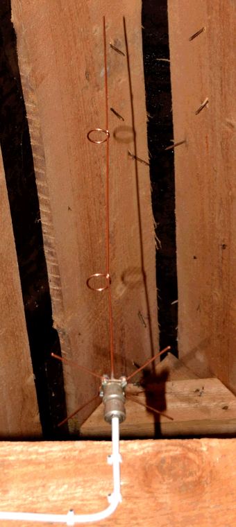
In this regard, it was decided to dwell on the "Vertical Collinear" design, namely, on this option:

View in good quality (
As the base of the antenna, I used part of the high-frequency connectorSR-75-166F : The
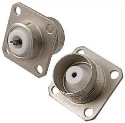
other part of the connector is connected to the cable for connecting the antenna to the DVB-T receiver. For this purpose, you must use the appropriate cable. From the forums I found out that a cable with a resistance of 75 Ω from a satellite TV is well suited .
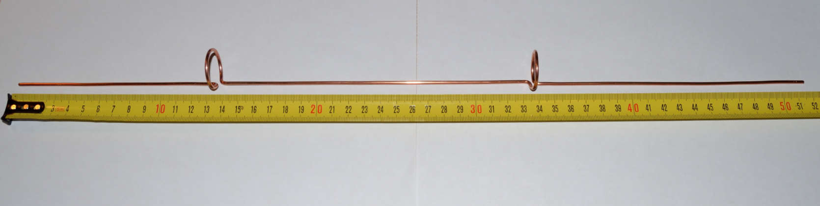
Elements of the antenna itself were made of copper wire Ø2 mm . The dimensions of the elements and the assembly diagram are on the drawing .
The main difficulty is the creation of 2 turns of a given length L = 69 mm . Here I adapted a tube of a suitable diameter and this is what ended up:
When installing this design in an open space (the most optimal option), the entire assembly is usually placed in a special casing made of a PVC tube of the appropriate diameter in order to avoid oxidation of copper elements and to set additional strength.
I simplified the task a bit and placed the entire structure under the roof:
3.3 software and hardware
Officially, flightradar has software for Windows , Linux , OSX and Raspberry Pi . A special thrill from this list is caused by Linux support, as In this case, you can try to deploy the entire kitchen on a regular home router with a USB port and custom firmware (OpenWrt). But more about that another time.
It was decided to run this task on an existing Linux server running CentOS 6.7 x86_64 . All further installation steps will apply exclusively to this version of the OS !
The software package for flightradar24 consists of 2 modules:
- dump1090 - for receiving and decoding data;
- fr24feed - a daemon that will broadcast the received data to the flightradar24 server.
Unlike Ubuntu, for CentOS they do not have ready-made installation * .rpm packages, so all the software will have to be assembled manually, and some modules will need to be compiled from source. At the time of writing, the latest software from flightradar was 1.0.18-5 .
NTP setup
When transmitting data, the value of the exact time on the host machine at the time of receiving ADS-B packets plays a very important role . CentOS uses the ntpd daemon to synchronize time .
Configure NTP Service:
Open the file
Open the file
/etc/sysconfig/ntpdateand set SYNC_HWCLOCK=yesOpen the file
/etc/ntp.confand register the addresses of the NTP servers. In my case, it looks like this:
Configure the service to start and synchronize the time:server 0.by.pool.ntp.org
server 1.ru.pool.ntp.org
server 2.europe.pool.ntp.org# service ntpd start
# chkconfig --level 345 ntpd on
# ntpdate 0.by.pool.ntp.orgInstall fr24feed
We receive and unpack the archive: Inside the archive are: - a binary file; - a text file indicating the software version; - license agreement.
# wget http://feed.flightradar24.com/linux/fr24feed_1.0.18-5_amd64.tgz

# tar -zxvf fr24feed_1.0.18-5_amd64.tgzfr24feedversion.txtLICENSE.fr24feedWe decompose files into directories:
# cp fr24feed /usr/bin/

# chown root.root /usr/bin/fr24feed

# chmod 755 /usr/bin/fr24feed

# mkdir -p /usr/share/doc/fr24feed

# cp LICENSE.fr24feed /usr/share/doc/fr24feed

# chown -R root:root /usr/share/doc/fr24feed

# chmod 755 /usr/share/doc/fr24feed

# chmod 644 -R /usr/share/doc/fr24feed/*.*
Attempt to run: In response, in most cases, we will get this warning: which indicates that the system does not have the necessary libraries. Everything here is simple and complicated at the same time: you need to upgrade the libc and libstdc ++ libraries to the necessary versions. If you use the standard CentOS repositories, then anyway the necessary library versions will not be there. Switching to CentOS 7 will not completely solve this problem. The library is included in the GCC 4.9 package, which will have to be assembled manually.
# cd /usr/bin/

# ./fr24feed
./fr24feed: /lib64/libc.so.6: version `GLIBC_2.14' not found (required by ./fr24feed)
./fr24feed: /usr/lib64/libstdc++.so.6: version `GLIBCXX_3.4.19' not found (required by ./fr24feed)
./fr24feed: /usr/lib64/libstdc++.so.6: version `CXXABI_1.3.8' not found (required by ./fr24feed)
./fr24feed: /usr/lib64/libstdc++.so.6: version `GLIBCXX_3.4.20' not found (required by ./fr24feed)libstdc++.so.6Go:
Before starting the assembly of GCC, it is necessary to deliver the modules that will be needed in the process: Downloading additional components: Configuration ( - compile a 64-bit compiler; - set of supported languages): Assembly and installation:
# wget https://ftp.gnu.org/gnu/gcc/gcc-4.9.3/gcc-4.9.3.tar.gz

# tar -zxvf gcc-4.9.3.tar.gz

# cd gcc-4.9.3/
Before starting the assembly of GCC, it is necessary to deliver the modules that will be needed in the process: Downloading additional components: Configuration ( - compile a 64-bit compiler; - set of supported languages): Assembly and installation:
# yum install gcc gcc-c++

# yum install zip
# ./contrib/download_prerequisites--disable-multilib--enable-language=c,c++# ./configure --disable-multilib --enable-language=c,c++# make && make installThe package building process will take quite a long time. On a virtual machine with one core and 1 Gb of RAM, it took 5-6 hours of time and 6 Gb of disk space.
When the package is installed, the libraries will be copied to
/usr/local/lib64. In order for them to become available to the application, it is necessary to register the path in the environment variable LD_LIBRARY_PATH. In order for the value of this variable to be available after rebooting the system, we will make changes to the file
.bashrclocated in the user's home directory:export LD_LIBRARY_PATH=$LD_LIBRARY_PATH:/usr/local/lib64Libc.so.6 update
libc.so.6Download packages for updates :
Install:
For reliability, it is better to check fr24feed again.# wget http://ftp.vim.org/ftp/pub/ftp/os/Linux/distr/redsleeve/steam/glibc-2.15-60.el6.x86_64.rpm
# wget http://ftp.vim.org/ftp/pub/ftp/os/Linux/distr/redsleeve/steam/glibc-common-2.15-60.el6.x86_64.rpm
# wget http://ftp.vim.org/ftp/pub/ftp/os/Linux/distr/redsleeve/steam/glibc-devel-2.15-60.el6.x86_64.rpm
# wget http://ftp.vim.org/ftp/pub/ftp/os/Linux/distr/redsleeve/steam/glibc-headers-2.15-60.el6.x86_64.rpm# rpm -Uvh glibc-2.15-60.el6.x86_64.rpm glibc-common-2.15-60.el6.x86_64.rpm glibc-devel-2.15-60.el6.x86_64.rpm glibc-headers-2.15-60.el6.x86_64.rpmInstall dump1090
Put required for USB components: Connecting our "whistle" and check to see how it "sees" the system: This response indicates the correct definition of device: For dump1090 need a set of libraries librtlsdr . In fact, rtl_sdr is a driver that provides “misplaced” use of the tuner and allows you to receive ADS-B signals. Fortunately, EPEL repositories have a ready-made * .rpm package: you can install dump1090 by building from source (a project on GitHub), or again download a * .rpm package at your own risk (oh, how I love everything ready) from the OpenSuse repositories:
# yum install libusb1

# yum install usbutils
# lsusbBus 001 Device 002: ID 0bda:2838 Realtek Semiconductor Corp. RTL2838 DVB-T# wget http://dl.fedoraproject.org/pub/epel/7/x86_64/r/rtl-sdr-0.5.3-3.el7.x86_64.rpm
# yum install ./rtl-sdr-0.5.3-3.el7.x86_64.rpm# wget http://download.opensuse.org/repositories/hamradio/openSUSE_Tumbleweed/x86_64/dump1090-1.10.3010.14-3.17.x86_64.rpm
# yum install ./dump1090-1.10.3010.14-3.17.x86_64.rpmFirst start
And so, we are almost close to the goal, there are only a couple of actions left:
1. Check in on flightradar24 .
2. Run fr24feed:
Step-by-step setup will begin - follow the instructions:
Enter the e-mail address that you specified during registration If you have previously broadcast data to flightradar, thenyou can skip this item you probably should have a unique key - enter it, or leave the field empty If you wish, we can participate in calculating the coordinates of aircraft using MLAT technology - at your discretion. If you are near the airport, enter the airport code or leave the field blank. Enter the coordinates (latitude and longitude) of the antenna location with an accuracy of 4 characters after comma. Well, the ubiquitous Google Maps will help us out here. Indicate (in feet) the height of the antenna position above sea level (see here
) The program will generate and issue a request for continuation. Select the receiver type. The program checks the location of dump1090. If necessary, you can set additional parameters. Allow data exchange over 30002 and 30003 ports. Set the size and location of the * .log file . This completes the preliminary setup of fr24feed. The parameters will be saved in the /etc/fr24feed.ini file. In addition (read between the lines), you will receive a unique radar identifier and an exchange key.
# cd /usr/bin

# ./fr24feed --signup
Step-by-step setup will begin - follow the instructions:
Enter the e-mail address that you specified during registration If you have previously broadcast data to flightradar, then
Step 1.1 - Enter your email address (username@domain.tld)

$:my_email@google.com
Step 1.2 - If you used to feed FR24 with ADS-B data before enter your sharing key.
$:Step 1.3 - Would you like to participate in MLAT calculations? (yes/no)$:noStep 2 - Enter nearest airport code (IATA or ICAO)
Enter airport code or leave empty$:Step 3.A - Enter antenna's latitude (DD.DDDD)
$:ваша_широта
Step 3.B - Enter antenna's longitude (DDD.DDDD)
$:ваша_долгота) The program will generate and issue a request for continuation. Select the receiver type. The program checks the location of dump1090. If necessary, you can set additional parameters. Allow data exchange over 30002 and 30003 ports. Set the size and location of the * .log file . This completes the preliminary setup of fr24feed. The parameters will be saved in the /etc/fr24feed.ini file. In addition (read between the lines), you will receive a unique radar identifier and an exchange key.
Step 3.C - Enter antenna's altitude above the sea level (in feet)

$:ваша_высота
Validating email/location information...OK
Enter your choice (yes/no)$:yesStep 4.1 - Receiver selection:
1 - DVBT Stick (USB)
Enter your receiver type (1-7)$:1Checking for dump1090...FOUND
Step 4.3 - Enter your additional dump1090 arguments or leave empty
$:Step 5.1 - Would you like to enable RAW data feed on port 30002 (yes/no)$:yes
Step 5.2 - Would you like to enable Basestation data feed on port 30003 (yes/no)$:yesStep 6A - Please select desired logfile mode:
2 - 72 hour, 24h rotation
Select logfile mode (0-2)$:2
Step 6B - Please enter desired logfile path (/var/log):
$:/var/log/fr24feed
Submitting form data...OK
Saving settings to /etc/fr24feed.ini...OK3. Creating the fr24feed daemon
By default, fr24feed is not able to work as a service and this complicates the process a bit. To solve such problems, there is a start-stop-daemon utility that allows you to start any process in the form of a daemon with the subsequent transmission of signals to it.
Place the file in the directory.
Register and our daemon to automatically start:
Run the service:
# wget http://download.opensuse.org/repositories/home:/sschapiro:/openstack:/IS24/RedHat_RHEL-6/x86_64/start-stop-daemon-1.9.18-2.4.x86_64.rpm

# yum install ./start-stop-daemon-1.9.18-2.4.x86_64.rpm/etc/init.d# chkconfig --add fr24feed
# chkconfig --list fr24feed# service fr24feed start4. Add rules to iptables
fr24feed has a small web-based admin panel located on port 8754 , which allows quick access to the list of monitored boards and program settings:
# iptables -A INPUT -p tcp -m tcp --dport 8754 -j ACCEPT

# iptables-save | tee /etc/sysconfig/iptables

# service iptables restart
Look like that's it! At this stage, the installation and configuration of the software can be considered completed.
4. Debriefing
After some working period, our data were received on flightradar24 and statistics were collected. All statistics are displayed on the site in the form of diagrams. Some charts display statistics for the day, while using the UTC time format , others - for the last 7 days.
4.1 Analysis of activity diagrams
Polar plot
One of the indicators characterizing the antenna is the radiation pattern. Flightradar24 displays the number of received ADS-B packets and the maximum distance from which they were sent on a pie chart in sectors. Such statistics are generated within 24 hours:
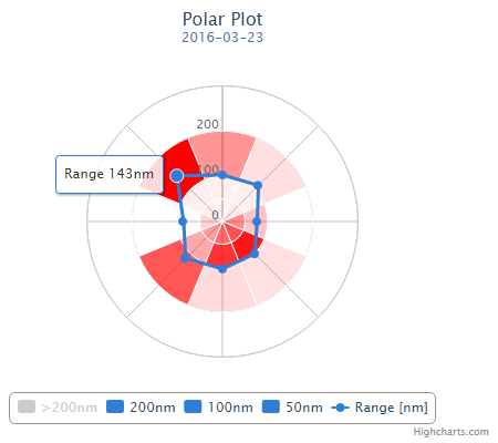
From this figure it can be seen that the maximum distance from which packets were received is 143 nautical miles, or ≈264.8 km. This indicator, given the fact that the antenna is under the roof, is quite good. In addition, using this chart, you can identify obstacles that impair signal reception (trees, hills, tall buildings, etc.).
Histogram
If you look at the dependence of the number of packets received on the distance, then everything is not as rosy as it seemed at first glance:

As you can see, the peak of the packets falls at a distance of 45 nautical miles, or a little more than 80 km. From this histogram, one can judge the effectiveness of the entire structure. The range of reception of packets is influenced by factors such as the design and placement of the antenna itself, the length of the cable from the antenna to the receiver, the type of receiver, the presence of external factors in the signal path (trees, landscape features, tall buildings, sources of interference, etc.).
Hits and positions reported
This type of chart shows the total number of all packets received from aircraft (Hits) and the number of packets containing the coordinates of the aircraft (Positions).
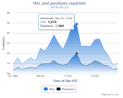
The coordinates transmitted by the aircraft are encoded in CPR ( Compact Position Reporting ) format and for full decoding we need to have 2 packets (even and odd). Due to interference, part of the packets may be lost, in addition, the aircraft does not always send packets containing the current coordinates - therefore, the graphs have a discrepancy.
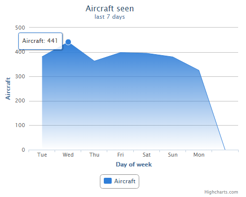
Aircraft seen
You can see how many aircraft the system recorded every day for the past 7 days.
4.2 What happened
As a result, a fully operational system was obtained, which is capable of receiving and decoding data from aircraft flying in the radius of its operation. The received data is transmitted to a popular resource and is available in the form of a dynamic flight map for everyone.
To increase the radius of coverage, you can (need) take the antenna out by placing it in a protective housing. You can also reduce the length of the cable to the receiver and / or set the low-noise amplifier to 1090 MHz .
Probably the most time-consuming software installation option is considered here. When installing from a * .deb package on an OS of the Ubuntu (Debian) family, or downloading software for Windows, the number of steps will be significantly reduced.
That’s all. In the process of publication, errors and inaccuracies could have crept into the material - I will be very glad if you point to them in the comments, or PM.
PS I almost forgot: in gratitude for the data transfer, flightradar24 will provide you with an extended premium account, which contains a lot of different options and “goodies”.