German-Chinese appliance and some math
- Tutorial
To the madness of the brave we sing a song
Recently I accidentally found out about the existence of a charming device MG238 - a tester of electronic devices. I watched a couple of videos, got a little dumb, I found the author’s site (by the way, the project is open, I think that Chinese manufacturers do not pay copyright), looked at the diagram and went nuts completely. That is, the measuring part is represented by 3 controlled dividers and does IT measure everything that I saw in the video?
The first thought was - this is a fake, but there are reviews of people who bought this device and use it, and mostly positive. Then the second thought came - why didn’t I? There are many answers to this question, the main of which will be "Elder sister did not allow." For those who are in the tank - this is from the saying "Laziness was born before you." Well, okay, we drove through, but still, how IT works. The source codes are laid out, the scheme is given, you can see, but there was a desire to understand for yourself, since I did not have time to do it, then at least repeat it (if not in hardware, then in my head).
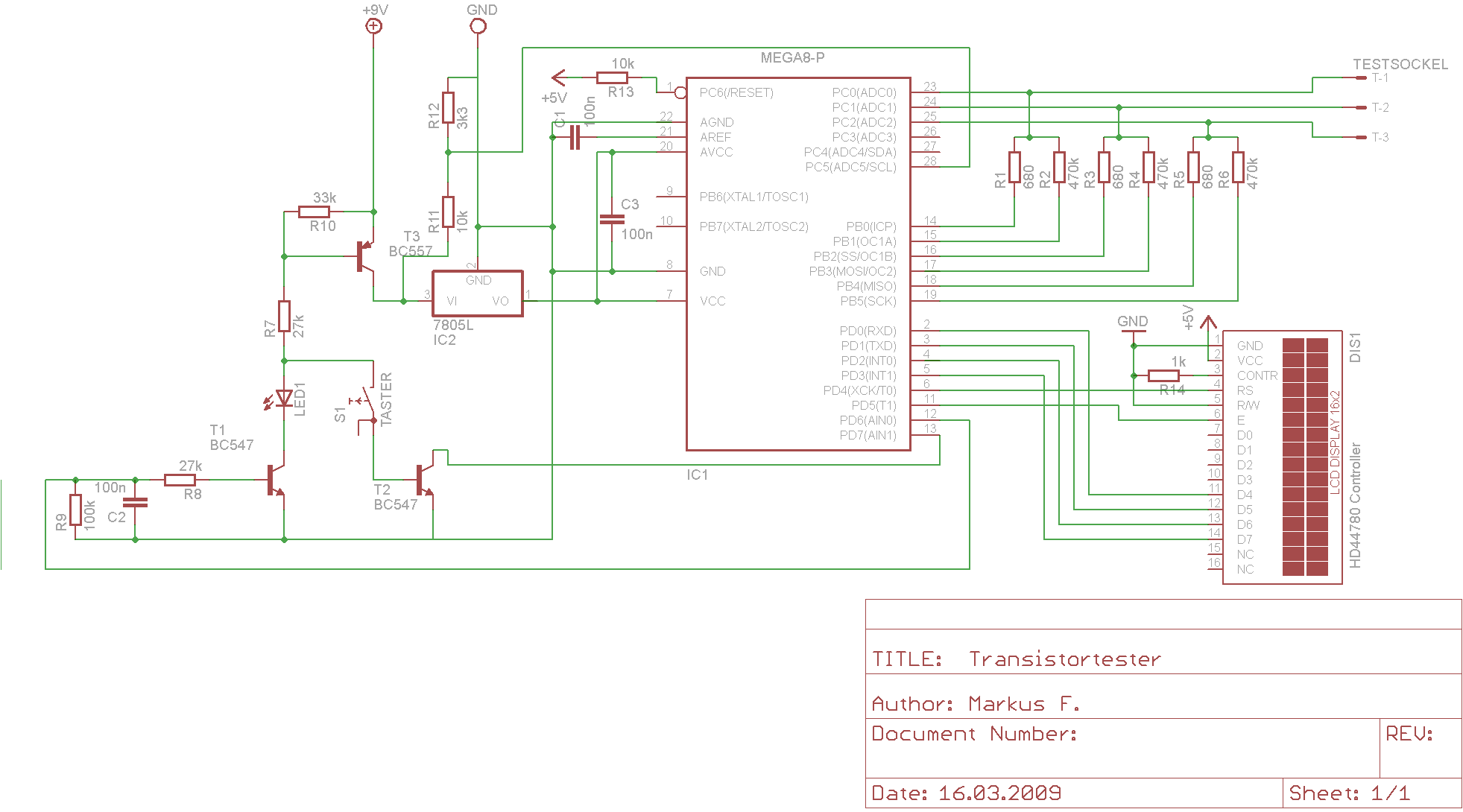
Let's start with, in my opinion, the simplest - measuring resistance. Let's try to understand the logic of the author of the development and its features. In the device diagram href = " www.mikrocontroller.net/wikifiles/f/f0/Schaltplan_transistortester.png”3 measuring points can be distinguished, each of which contains 2 resistances 680 Ohm and 470K Ohm, connected to the ADC input and to the MK ports. Based on the scheme, we can assume the following algorithm for determining the unknown resistance - we connect it between two measuring points, we connect power to one of them through the MK port through a resistor, and to the other - earth through the MK port combined with the ADC. We obtain a classical voltage divider for which the expression
Ux = Uo * Rx / (Rx + R0) is valid , where U0 is the supply voltage, R0 is the known resistance, and Rx is the resistance under study.
Now we measure the voltage Ux at the input of the ADC, we can calculate the value of the investigated resistance according to the formula
Rx = R0 * Ux / (U0-Ux).
Everything seems to be simple, but, as you know, the devil is hiding in the details. Let's try to determine the range of measured values. At first glance, the range of measured resistance extends from 0 to infinity, but in fact, when the resistance moves away from the known resistance, the measurement accuracy decreases, so it would be nice to determine the limit values of the resistance, measured with a certain predetermined accuracy at certain conditions.
How can we define this range? The first thing that comes to mind is a computational experiment. We take Excel, compile the table, enter the formulas and get the results - quite specific numbers, which, due to the linearity in terms of parameters, are easily scalable. But this is not our way, we prefer the analytical method of solution (although, of course, we did so in the beginning).
First of all, we assume that the values of U0 and R0 are known to us absolutely accurately (at least with respect to U0 this is really true, since we do not measure the real value of Ux, but scale it to the support voltage, which coincides with the voltage U0, so that we are completely not interested in its absolute value). With regard to the reference resistance, this assumption looks bolder, leave it to the calibration. Under these assumptions, the accuracy of the result obtained depends only on the accuracy of the measurement of Ux, which we will study.
The accuracy of the output result of the ADC operation depends on many factors, we sum them all up and turn it into a generalized indicator of the error dUx. Of course, this approach greatly simplifies the task, but it is quite workable, and for the first approximation, we can assume that the ADC in MK gives us 10 exact binary bits. Then the conversion error will be dUx = U0 / 2 ** 10 = U0 / 1024 (or for this circuit 5/1024 ~ 5mV, which is absolutely unimportant). We only need to remember the figure 1/1024 - the unit of the least significant bit and, accordingly, the measurement error.
We study the behavior of the function Rx (Ux) = R0 * Ux / (U0-Ux) with small changes near Uxo represented as Ux = Ux0 + dUx, in a first approximation we get Rx (Ux) = Rx (Uxo) + dUx * Rx` (Ux0), given that Rx` (Ux0) = R0 * U0 / (U0-Ux) ** 2, we find that dRx = dUx * R0 * U0 / (U0-Ux0) ** 2, hence qRx = dRx / Rx = dUx / Ux0 * U0 / (U0-Ux0) = qU * U0 / Ux0 * U0 / (U0-Ux), or, dividing both parts by U0 * U0
qRx = qU / (K * (1-K)) , where K = Ux0 / U0, or qRx / qU = 1 / (K * (1-K)).
Denoting the target value by qM, we obtain the quadratic equation
K ** 2-K + 1 / qM = 0, the solution of which is the values
K1,2 = (1 + -sqrt ((qM-4) / qM)) / 2.
To begin with, we see that qM cannot be less than 4 if we do not seriously consider complex resistances, that is, in the best case, when K = 1/2, that is, the resistance of the studied resistor is equal to the resistance of the standard, the accuracy of measuring the resistance is 4 times worse, than the maximum achievable accuracy of the ADC. Further, we see that as the value of K deviates from 1/2, the measurement error increases and in the limit goes to infinity. A little bit about why this is happening. On the left side, with a decrease in the measured value and with a fixed measurement error, the relative error will inevitably increase, so everything is expected here. But on the right side, the case is a little trickier - pay attention to the denominator U0-Ux. Again, with a constant absolute error, the relative error of the entire denominator as a whole will again increase,
Now it is possible to calculate - let us set the required accuracy to 1%, taking into account qU ~ 0.1% we get qM = 10 and, accordingly, K1 = 0.89 K2 = 0.11. From these values, it is easy to obtain Rmax / R0 = 7.87 and Rmin / R0 = 0.13. That is, if we set the value of the reference resistor to 680 Ohm, we can measure resistors with a nominal value from 86 ohms to 5k3 with the accuracy specified above by the above method, and for the 470k resistor the corresponding range will be from 59k6 to 3700k, it is obvious that outside these limits accuracy will be lower. Strictly speaking, the dynamic range in this case is 62, that is, we must put 1000/62 = 16 reference resistors in the resistance range of 1 to 1000. Since we have only 2 reference resistors, we will see what accuracy is achievable with overlapping their ranges - if we set an accuracy of 3%, then we can measure with such accuracy resistors from 24 Ohm to 13 MΩ with just two reference resistors, and the range for one resistor is 1 to 782 (close enough to 680 to 470000). Perhaps this accuracy was accepted as required by the developer of the device. Moreover, outside this range, accuracy decreases and 5% accuracy is achievable in the range from 14Ω to 22MΩ. Considering that resistors are usually measured with an accuracy of 5%, the result can be considered satisfactory, although it is also difficult to call it good. On the other hand, the device is not positioned as a measuring one, but as a tester, that is, with an accuracy of 5% it is quite possible to assess whether the resistor is working. such accuracy was accepted as required by the developer of the device. Moreover, outside this range, accuracy decreases and 5% accuracy is achievable in the range from 14Ω to 22MΩ. Considering that resistors are usually measured with an accuracy of 5%, the result can be considered satisfactory, although it is also difficult to call it good. On the other hand, the device is not positioned as a measuring one, but as a tester, that is, with an accuracy of 5% it is quite possible to assess whether the resistor is working. such accuracy was accepted as required by the developer of the device. Moreover, outside this range, accuracy decreases and 5% accuracy is achievable in the range from 14Ω to 22MΩ. Considering that resistors are usually measured with an accuracy of 5%, the result can be considered satisfactory, although it is also difficult to call it good. On the other hand, the device is not positioned as a measuring one, but as a tester, that is, with an accuracy of 5% it is quite possible to assess whether the resistor is working.
There is one more idea, you can expand the range by connecting the other end to the ground through a reference resistor. In this, the resistance of the standard will double and the upper limit of the range should also double. True, we must measure 2 voltage values, which worsens the initial accuracy, we should calculate what happens, but it's too late.