Porting Arm Mbed OS to a dedicated controller
Arm Mbed OS is a popular open source project accelerating the development of devices for the Internet of Things (IoT). If you created your own unique processor device, then the first task will be to port some operating system (OS) to it.
Here is a step-by-step instruction on how to launch Arm Mbed OS on a board with an NXP Kinetis family of microcontrollers .
Arm Mbed OS Project
is a property of ARM and is intended solely for the ARM architecture. Contrary to popular belief, Mbed is not written entirely in C ++, is not tailored exclusively for Cortex-M, and is not so new. Its origins lie back in the 90s when Keil created RTX - the real-time operating system (RTOS) for the I8051. Subsequently, RTX was transferred by Keil to ARM7 and ARM9, and then Cortex appeared.ARM acquired Keil and RTOS was named CMSIS-RTOS . She was still entirely written in C . Finally, with the advent of the IoT and Arduino boomers , Mbed appeared . WaveArduino was pushed to make a C ++ shell and a simplified API with a familiar set of several dozen pins, a UART and an LED, and IoT filled the project with TCP / IP, Bluetooth Low Energy, 6LoWPAN, Thread ... But RTX5 still sits in the depths of the Mbed OS sources .
The Keil brand continues to exist and in the Keil development kit distribution you can find CMSIS-RTOS with a large selection of middleware and porting examples to a wider range of microcontroller families than Mbed offers . However, this is a closed commercial project.
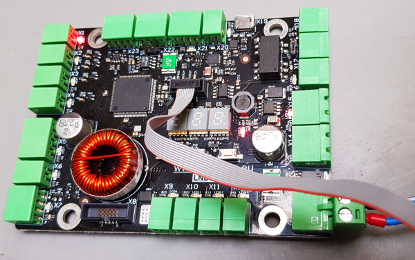
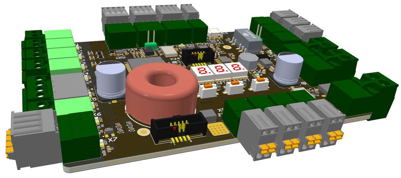
Specialized Board
the porting to which is taken here is taken as an example and its scheme is not of great importance. More important is the microcontroller that is installed on it. It MKE18F512VLL16 family Kinetis NXP's firm. Its main parameters:
Core - ARM Cortex-M4F 32-Bit
Maximum core frequency - 168MHz
Flash 512KB (512K x 8)
RAM 64 KB
100-LQFP (14x14)
Microcontroller contents

This microcontroller is not in the list of supported ARM Mbed OS. It can be explained by the fact that it is relatively new .
The microcontroller is interesting with a good set of peripherals at a fairly modest price and a high core frequency. The FlexIO module makes it possible to create non-standard interfaces that are not available on conventional microcontrollers.

Step 1. Download NXP Tools
- We configure our version of the MCUXpresso Software Development Kit (SDK) for the MKE18F512xxx16 family online at www.nxp.com
- When you need to specify the Toolchain / IDE, select the IAR IDE . Further work will be considered in the IAR IDE .
- Select all available Software Components .
- Download the resulting MCUXpresso Config Tools, Windows 64bit package from the site.
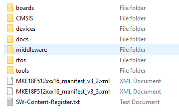 This will be a 30 megabyte MKE18F512xxx16.zip archive with the following contents:
 - - Download also MCUXpresso Config Tools v4.1 for Windows . Using it, we will configure the clock subsystem of the microcontroller.
Step 2. Obtaining an application project without RTOS
- Launch MCUXpresso Config Tools v4.1 for Windows
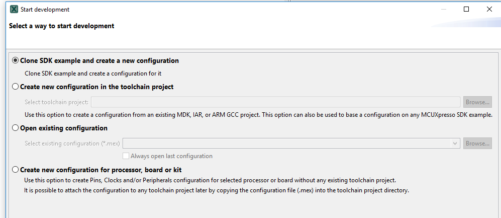
- As a template, we select one of the simplest demo projects - led_blinky.

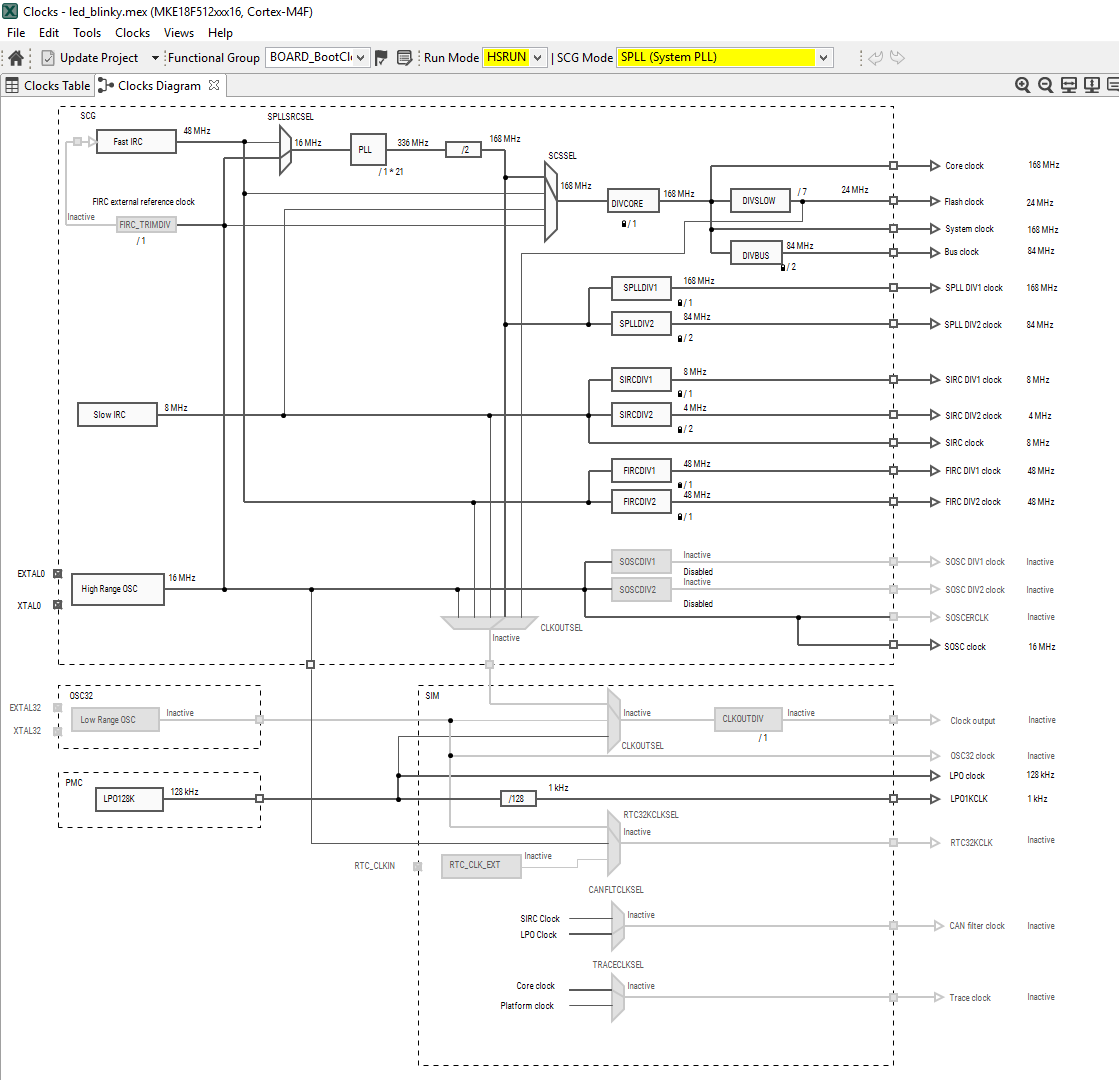
- We set up the clocking scheme and give a command to generate the clock initialization sources. Initialization sources are updated directly in the project directories.
- We copy the received project with sources under the IDE IAR to our directory. In the project, select the J-Link debugger , the debug channel through the SWD interface . We modify the write commands to the LED port, compile and upload to the board.
Step 3. Configure and convert the Mbed project
- We go to the Mbed project website in the platform section - os.mbed.com/platforms .
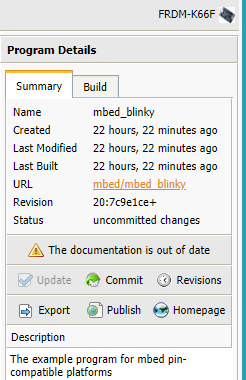
There we are looking for a board with a microcontroller as similar as possible to our chosen one. - We select the FRDM-K66F board - os.mbed.com/platforms/FRDM-K66F . The choice is not random, with such a microcontroller there is work experience .
- On the board presentation page, we decide to choose a demo - mbed-os-example-blinky - os.mbed.com/teams/mbed-os-examples/code/mbed-os-example-blinky/?platform=FRDM-K66F
This is the most a simple example and it will be easiest to adapt for another board. - We register and go to the on-line section of the compiler - os.mbed.com/compiler
- First, select the platform - FRDM-K66F , and then import the demo chosen by us - mbed-os-example-blinky . In the Programs panel, this demo will be called mbed_blinky .
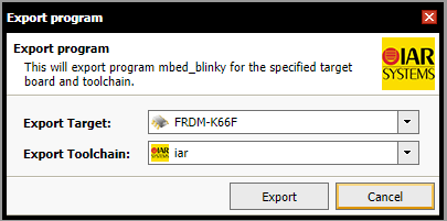
- We compile this example for verification, and then export it.
We export in the format intended for IDE IAR
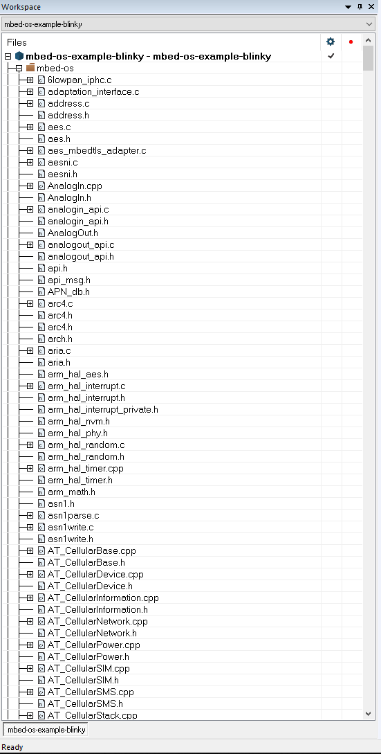
Now we have received the source code of the Mbed working draft for IAR . However, the resulting project is inconvenient for work.
All files in the project were collected in one group and mixed. It is impossible to search and identify which file belongs to which functional package. The project involves the sources of almost all the middleware of the Mbed project , although most of them we do not need now.
Step 4. Converting the IAR Project to Normal Form
- Using specially written utilities in Python, we perform several conversion operations.
First, we remove from the directories of the demo project all the sources that did not fall into the project. The source list is obtained from the file mbed-os-example-blinky.ewp . The utility is called Clear_from_unused_files_and_dirs.py . It also removes empty directories created after deleting files.
Secondly, using the Convert_ewp_file.py utility , we reconfigure the project file mbed-os-example-blinky.ewp so that the groups in it correspond to the project directories. We get the project with a more understandable structure, where you can remove or add packages. Here we can rename the project. To do this, edit the tag
mbed-os-example-blinky $WS_DIR$/mbed-os-example-blinky.ewp 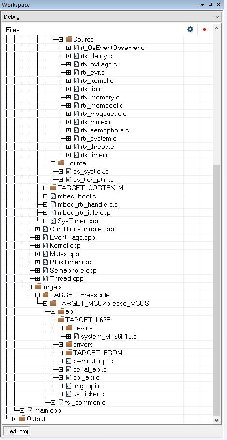
As a result, it has such a project structure
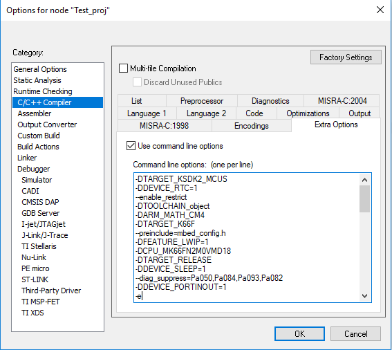
- We study the source code to determine those that depend on the features of the microcontroller. For this, it is more convenient to use more specialized editors, such as SlickEdit or Eclipse . The editor should also inform about the macros declared in the IDE settings . To do this, create an extra header file Extra_options.h and copy the contents of Extra Options fromIDE IAR .
Step 5. Editing the Mbed Project
We are ready to edit the project. Let's start by analyzing the macros in the Extra_options.h file . We do this in the editor with the corresponding capabilities, and you can do it in the IAR environment.
- Delete unused macros so that they do not distract attention during further analysis. We sort the rest. About half of the macros turned out to be unused.
- In the Extra Options we introduce a new macro - TARGET_MKE18F . It determines the starting address of the stack in the mbed_rtx.h file . The stack is growing in the direction of decreasing addresses. In Mbed, it is customary for a stack to start from the upper limit of available RAM. For MKE18F, set this border to 0x20008000UL
- Find the directory TARGET_K66F. Files that depend on the type of microcontroller are stored there. There are quite a lot of them - 136 files. Next to the TARGET_K66F directory, create your own with the name TARGET_MKE18F .
- From the directory of the demo project SDK led_blinky \ CMSIS, copy the following files to the Mbed directory - os \ targets \ TARGET_Freescale \ TARGET_MCUXpresso_MCUS \ TARGET_MKE18F \ device :
• fsl_device_registers.h. (macro CPU_MK66FN2M0VMD18 in Extra Options is replaced by CPU_MKE18F512VLL16)
• MKE18F16.h
• MKE18F16_features.h
• system_MKE18F16.h
• system_MKE18F16.c
- Delete files
• MK66F18.h
• MK66F18_features.h
• system_MK66F18.c
• system_MK66F18.h
- In the TOOLCHAIN_IAR directory , replace the contents with the startup_MKE18F16.s and MKE18F512xxx16_flash.icf files .
- The project IDE IAR also for the linker, specify the path to the new file MKE18F512xxx16_flash.icf
- Content directory Mbed-os \ targets \ TARGET_Freescale \ TARGET_MCUXpresso_MCUS \ TARGET_MKE18F \ drivers erase and fill the files in the directory devices \ MKE18F16 \ drivers located in the SDK family MKE18F512xxx16
- Replace file \ mbed-os \ targets \ TARGET_Freescale \ TARGET_MCUXpresso_MCUS \ fsl_common.c to the same from the devices \ MKE18F16 \ drivers directory located in the SDKMKE18F512xxx16 family . In the directory Mbed-os \ targets \ TARGET_Freescale \ TARGET_MCUXpresso_MCUS \ TARGET_MKE18F \ drivers delete the same file.
- From the directory mbed-os \ targets \ TARGET_Freescale \ TARGET_MCUXpresso_MCUS \ TARGET_MKE18F \ drivers we delete files in the name of which FreeRTOS is present.
- From the \ mbed-os \ features \ netsocket \ emac-drivers directory, delete all files associated with the EMAC peripherals of the K66 microcontroller, since the new microcontroller does not have EMAC.
- We use the Convert_ewp_file.py utility again
- We compile and get 267 errors. They are all in files located in the TARGET_MCUXpresso_MCUS directoryand having mostly api suffix in the name . Each file must be dealt with separately. A total of 12 files appear with errors.
Step 6. Editing Mbed Files
Fsl_clock_config.c file
This is the most important file at this stage. It initializes the clocking of all subsystems of the chip. The RTOS initialization function mbed_sdk_init calls the BOARD_BootClockRUN function from this file . Replace the fsl_clock_config.c file with the verified file from the led_blinky project . There it is called clock_config.c (we rename it after copying to fsl_clock_config.h and fix #include in it where necessary), and replace the BOARD_BootClockRUN function call in RTOS files with BOARD_BootClockHSRUN , because we want to start the chip at the maximum frequency of 168 MHz .
- We consider the remaining files. Immediately raise doubts about their necessity. Indeed, many of them are simple wrappers on peripheral functions with a simplified interface. Most likely, they are made for an audience of novice programmers, for whom the similarity of API systems based on Arduino is important. We can neglect these files as not carrying a payload, although for this we will not be accepted into the Mbed community.
Files to be deleted:
API
• analogin_api.c
• analogout_api.c
• dma_api.c
• i2c_api.c
• pwmout_api.c
• spi_api.c
• dma_api_hal.h
Drivers
• AnalogIn.cpp
• I2C.cpp
• I2CSlave.cpp
• SPI.ccpp
SPIS
• AnalogIn.h
• AnalogOut.h
• I2C.h
• I2CSlave.h
• PwmOut.h
• SPI.h
• SPISlave.h
HAL
• analogin_api.h
• analogout_api.h
• i2c_api.h
• pwmout_api.h
• spi_api.h
- We edit the mbed.h file to comment out the connection of the files that we deleted. Also edit object.h .
- Let's edit the mbed_die function called when the system crashes . By default, it blinks an LED. We remove the blinking, we do not have such an LED.
- We clear the PinNames.h and PeripheralNames.h files from the declarations of pins and structures associated with the api deleted before this file
- We delete unnecessary arrays in the file PeripheralPins.c , after that it remains only to edit the pin map in it for UARTs.
- We slightly change the directory structure and the location of files in the targets subdirectory to reduce the randomness of naming and fragmentation of files.
List of remaining files requiring correction:
• serial_api.c
• trng_api.c
• flash_api.c
• sleep.c
• us_ticker.c
These files cannot simply be deleted, since important RTOS services depend on them. The problem is mainly that the MKE18F512xxx16 family uses a different naming of the periphery than MK66FN2M0VMD18 , although the periphery for the main APIs has remained virtually unchanged.
File serial_api.c
It basically changes the names of functions and enumerations inherited from the K66 chip. This file defines low-level functions for debugging RTOS output via UART.
Us_ticker.c file
It is important in that it determines the mechanism for obtaining exact time in ticks for RTOS (in our example, the tick value is 1 μs). This API is used in RTOS delay functions and in the event queue services with a specified activation time on the timeline. To organize a continuous time counter, the associated channels 0 and 1 of the PIT module are used. Channel 0 has a period of 1 μs, channel 1 ends the cycle after 429 seconds (0xFFFFFFFF is loaded into it, the channel counter is decremented). To organize the event queue, channels 2 and 3 of the PIT module are used with interruptions from channel 3. This way it turns out that Mbed occupied the entire PIT module and cannot be used for anything else.
Trng_api.c file
implements hardware random number generation. There is no such generator in the MKE18F512xxx16 chip , so we put the stubs from the standard C function rand . A good random number generator is needed for SSL and TLS data encryption protocols. So far we do not plan to use such on our board.File sleep.c
implements the functions of entering and exiting sleep mode. At the same time, the operation of the accelerator for working with Flash memory is affected. You need to adjust the names of the functions that enable and disable Flash memory cache.Flash_api.c file
implements functions for programming internal Flash memory. Here came across the fact that in the chips of the MKE18F512xxx16 family there can be two sections of Flash memory. We chose to work with section 0.- We will correct the macros with the values of the internal frequencies of the chip in the system_MKE18F16.h file
Linker file MKE18F512xxx16_flash.icf.
It must have a declaration of the __VECTOR_RAM character . This is the address from which the table of interrupt vectors in RAM will be placed. In Mbed OS, the interrupt vector table is always copied from Flash to RAM since it can be programmatically modified by the system during operation.
Curiosity
They ran into the fact that on the vector SVC_Handler there is a stub and is fixated on itself. And the initialization of Mbed OS calls this particular vector. Somewhere the moment of installation of the correct vector is missed. It turns out that they forgot to connect assembler files with the extension with the capital letter S to the IAR . And there the most important file with the context switch is irq_cm4f.S . Thanks to Python. We fix the Convert_ewp_file.py utility and run it again. We recompile the project.
How to revive a dead chip
When you initialize the GPIO ports, you may accidentally incorrectly initialize I / O lines for the debugger and quartz. In this case, the chip stops debugging and even stops being programmed with a J-Link SWD adapter. In our case, the problem can be solved simply. We short-circuit one output of the external quartz to the ground, remove the power and apply it again. Our program will not get to the wrong initialization of the GPIO because it will get stuck waiting for the quartz to turn on. At this time, programming of the SWD adapter becomes available again.
The problem of the wrong delay time of the wait function
By measuring the LED blinking period, a slowdown in the execution of the wait function was detected longer than expected exactly twice. To check the correctness of the internal frequency settings, we initialize the output to the external output of the internal PLL block divided by 8. We see the frequency of 21 MHz. All is correct.
When initializing the RTX tick frequency, the parameters of which are set in the RTX_Config.h file, the SystemCoreClock variable is used , and it, in turn, is assigned in the BOARD_BootClockHSRUN function during system initialization and is equal to 168000000. Here, too, everything is correct.
Tested window TimeLine debugger IARthe interrupt frequency of the system tick, it is 1 KHz, is also correct.
It turned out that the PIT module was incorrectly initialized . He stopped counting when RTX went into SLEEP mode. And RTX switches to this mode at every tick if there are no active tasks. Thus, the timer stopped, but its values were used in the wait function to ensure the most accurate delay. But we inherited this error from the official Mbed port for K66!
On the third day, the porting of ARM Mbed OS was completed successfully and the LED blinks.
github.com/Indemsys/Mbed_led_blinky_MKE18F