Automatic gas temperature controller
1. The source data
We live in a rented apartment, which has one very unpleasant property: the house does not have hot water, cold water is heated on the spot with a heater (Instantaneous Gas Water Heater - HSV ), which is located in the kitchen. During a shower, if there is another jump in pressure, you have to spank naked to the column or call someone. There is no way to integrate a full-fledged “smart home”, so it was decided to introduce automatic control of the heater. By the way, I quickly found several similar solutions, for example here , which means my problem is known and resolved in its form.
HSV model: Vector lux eco 20-3 (China)
Water pressure: about 1.5 kgf / cm² (low pressure, the heater works just above the allowable limit)
Decision requirements
- Simplicity
- PID controller or similar
- Ability to select supported temperature
- Display current settings
- Resolving device security issues
System architecture
After some thought, the device architecture was outlined as follows:
- Servo (directly in the body of HSV)
- Thermal sensor regular HSV
- Thermal sensor signal amplification unit and servo power supply stabilizer (directly in the body of HSV)
- Control unit (external)
Next, I will describe the development process in chronological order.
2. Servo
Since my profession is software and mechanics has always remained the most difficult part - I decided to start with it. I must say that for the first stage I could not get together for a long time, the HSV was very afraid to touch, but the next pressure drop forced me to start.
Having disassembled the column and looking around, I found places to install the TowerPro MG995 servo machine, which had somehow been ordered "for delivery" on aliexpress.
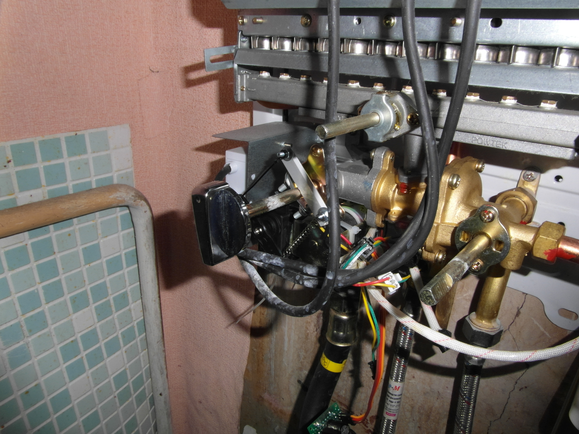
To eliminate the backlash of the drive rod made one rod spring-loaded. The backlash was completely eliminated, but another problem became clear - a servo with a moment> 10 kg * cm turned out to be too impudent for HSV. When you turn on transients in the electronics of the machine, they cause a jerk to a random position and after a couple of idle inclusions the thrust is bent! Silumin columns will not withstand such treatment. The rocking geometry, which was not on the axis of the regulator, also caused criticism - which led to non-linearity of adjustment. The final view of the throttle drive assembly:
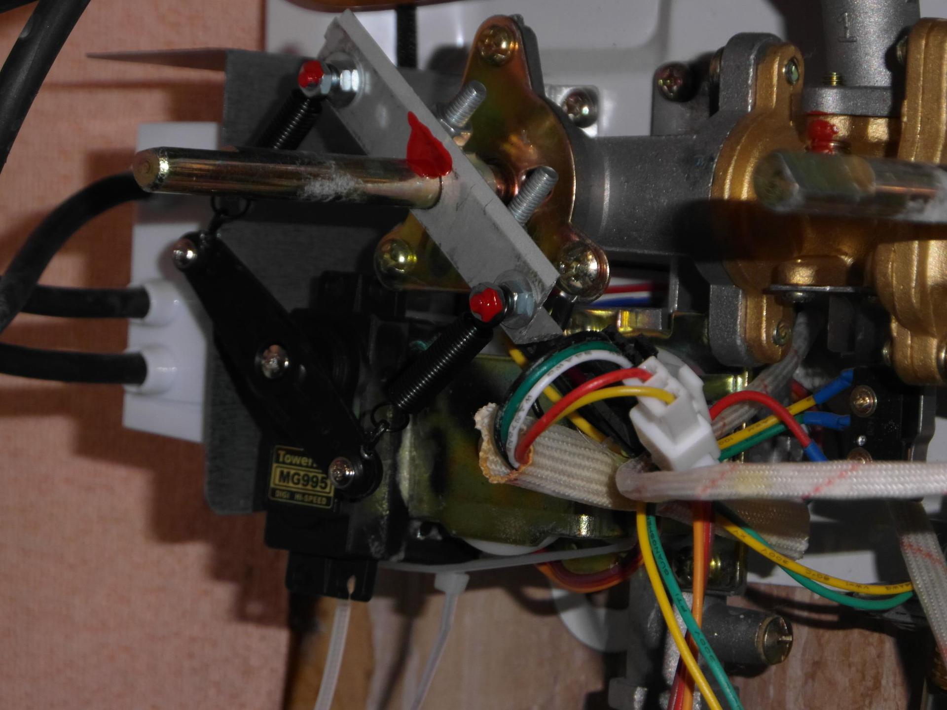
The assembly has been redone — springs from a VAZ (from a carburetor — purchased at an auto parts store) were used and the rocking chair is now on the geometric axis of the shaft. This design has a slight backlash, but it is linear in adjustment and can dampen the rage of the steering machine. The angles are set to the optimum values for adjustment in the most popular positions of the regulator.
3. Block sensors HSV
The HSV thermistor changes its resistance within 20..50 KOhm, it is problematic to use directly as a divider — we get a low measurement accuracy. But as it turned out in practice - if the supply voltage is increased to 12V, you can easily get an acceptable output signal range - only use the op-amp in the repeater mode (if necessary, you can change the gain) to isolate the divider from the load. Block diagram inside HSV:
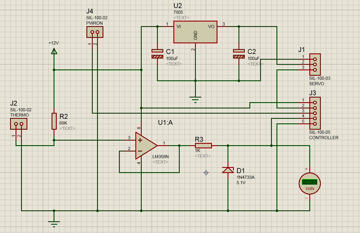
The divider R2 and the column temperature sensor generates a signal with a voltage of 1.4..4.96 V in the full measurement range (in practice, 20..60 degrees Celsius). Initially, he developed a bridge circuit - which can compensate for the departure of the power source, but was discarded due to the fact that the power source had little effect, and the first item “TK” was “simplicity”. The operational amplifier provides isolation of the divider and the load. Zener diode D1 limits the output voltage to 5.1 V for disconnecting the sensor (otherwise the output would be 12V - which is deadly for the controller) - that the controller circuit would be considered an absolute error. The 7805 integral stabilizer feeds the servo - the solution is unsuccessful, when the machine stops, it heats up terribly and I think it may fail with the drive wedge (if the built-in protection does not work).
4. The controller
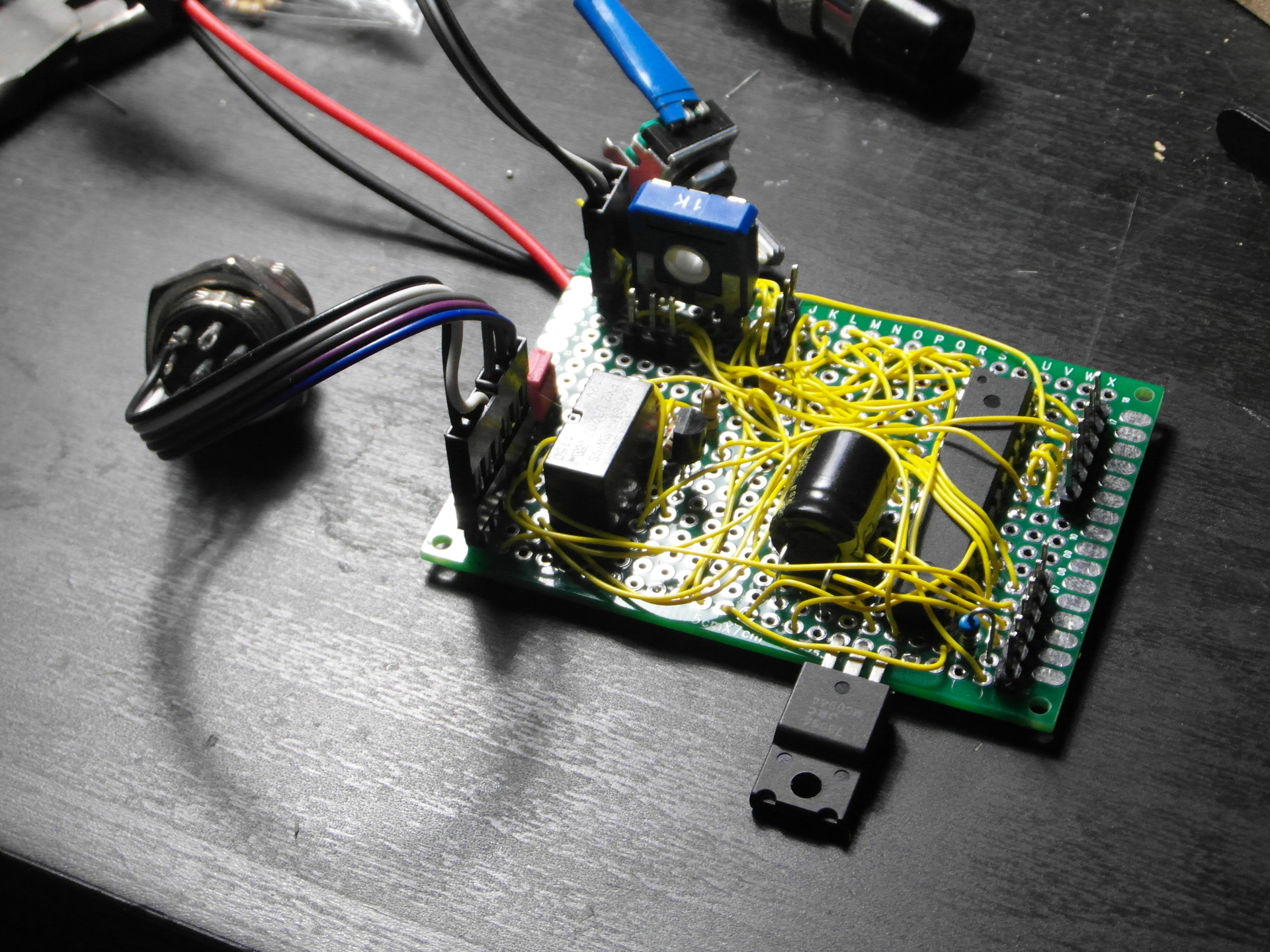
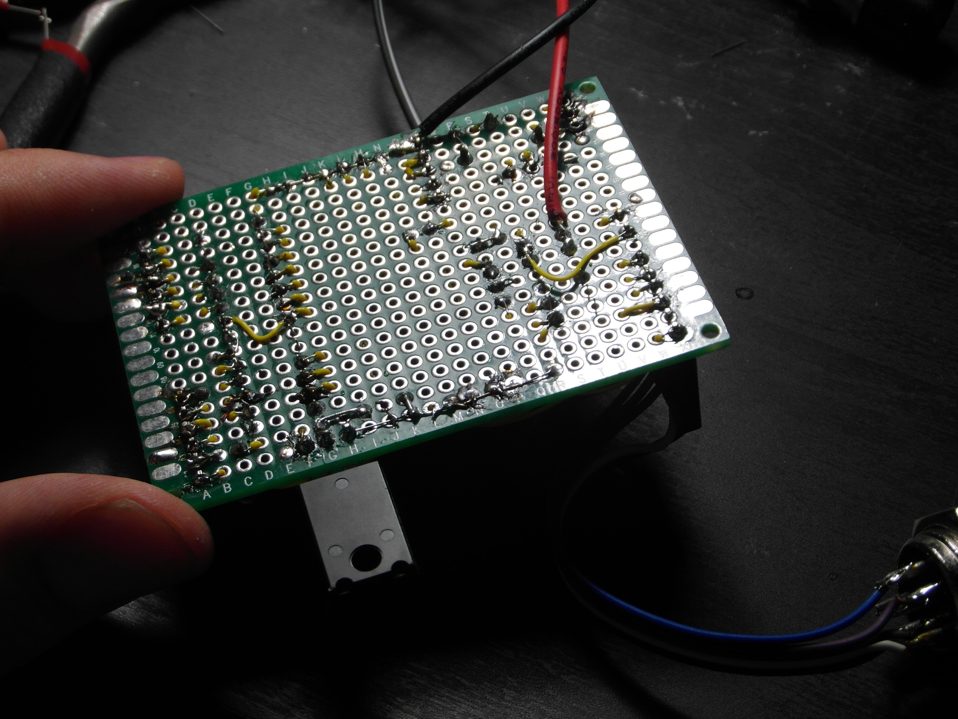
The controller is assembled on the basis of Atmega8 IC in a dip-case.
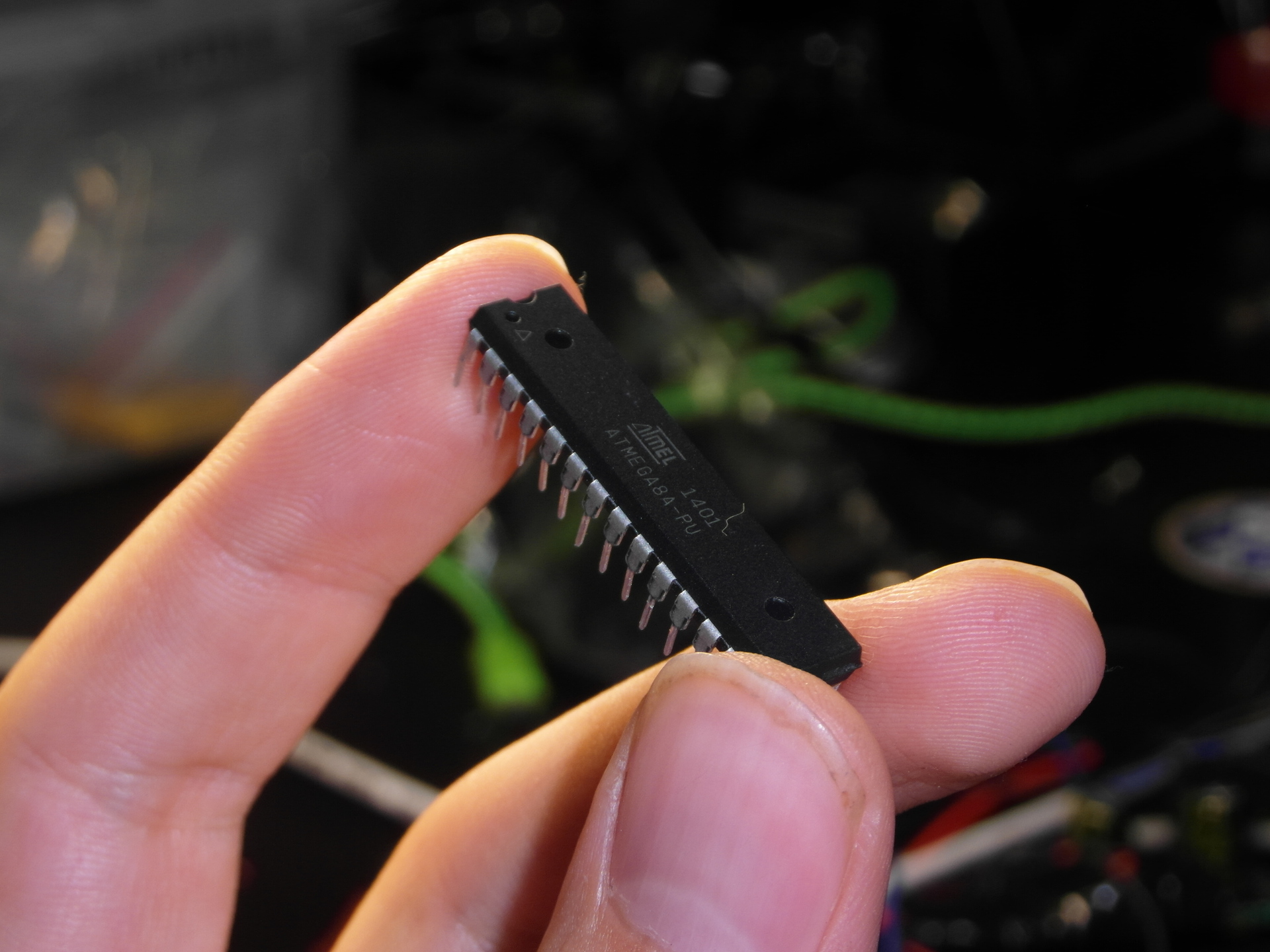
Clocking - 8 MHz internal oscillator. Power - another 7805 on the board. Indication through the standard LCD1602 display. Block diagram:
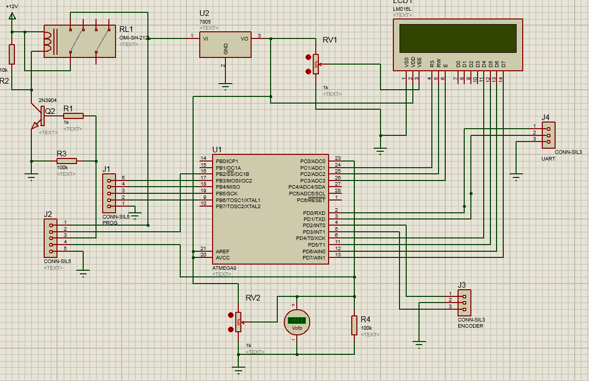
The power supply of the block is controlled from the column through a transistor - using a small-sized relay. The temperature sensor signal (Pin No. 4 of the connector) is pulled to the ground and when the sensor is disconnected during operation it will show a very high temperature - which will lead to a decrease in the regulator and will not cause dangerous situations. Assembled Block:
4. Testing and adjustment
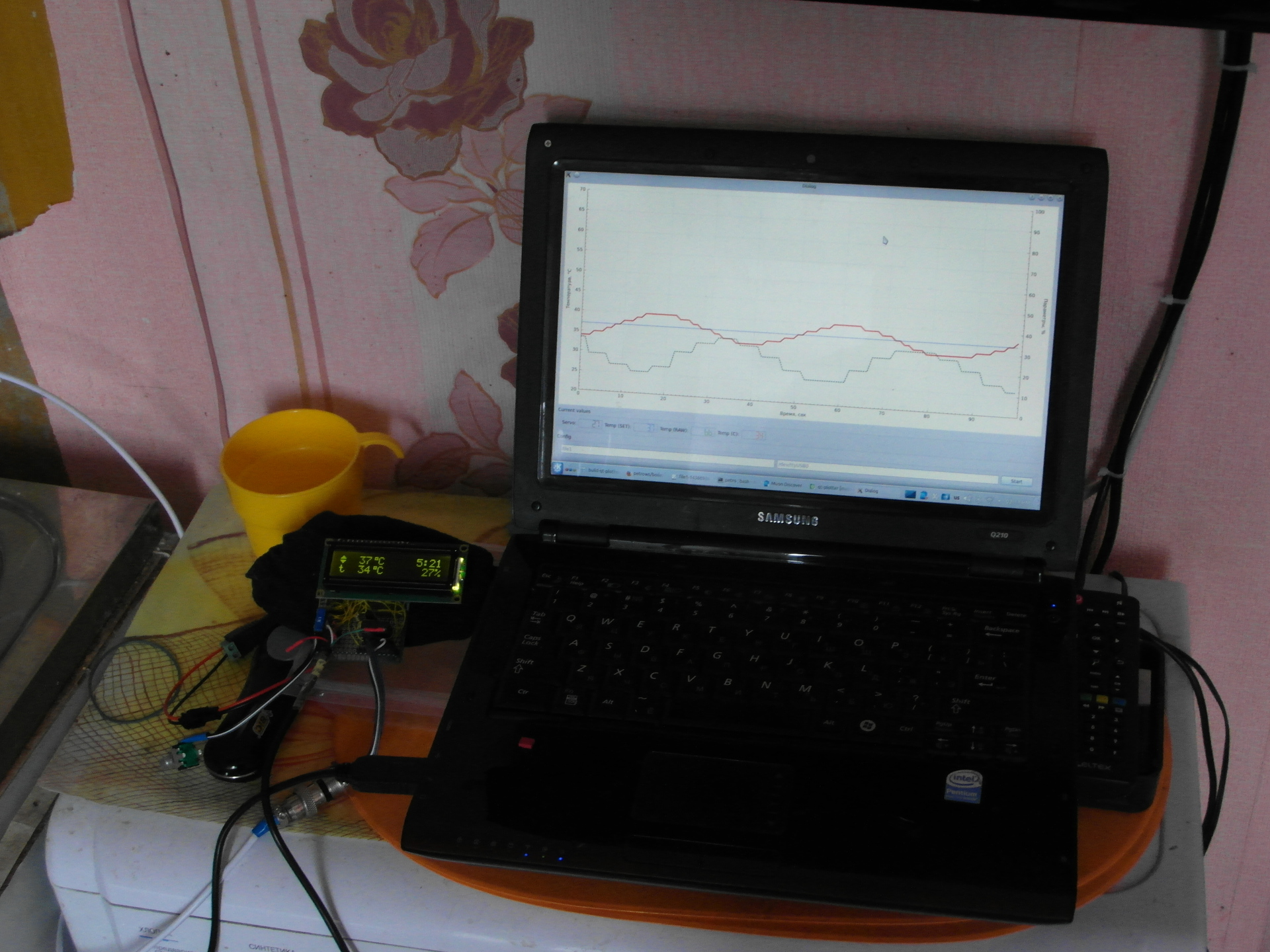
To test the PID controller, a HSV model was written in Qt. It worked out the main points and situations of the heater - start cold / hot, pressure drops. To take characteristics, a UART-connector was added to the controller board, where once a second data was sent on the indicators - the current temperature, the position of the throttle, etc.
During the tests revealed the following:
- Very large inertia of HSV from the onset of exposure to the reaction on the temperature sensor - about 30 seconds
- Rounding to a degree in the controller firmware is a bad idea, the algorithm may work more accurately
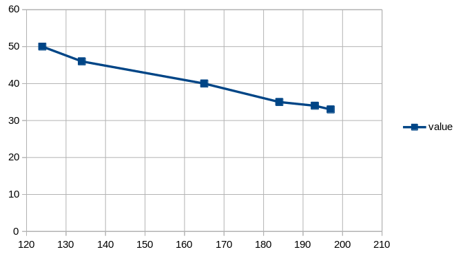
The results of measuring and calibrating the temperature sensor, Dependence can be considered conditionally linear:
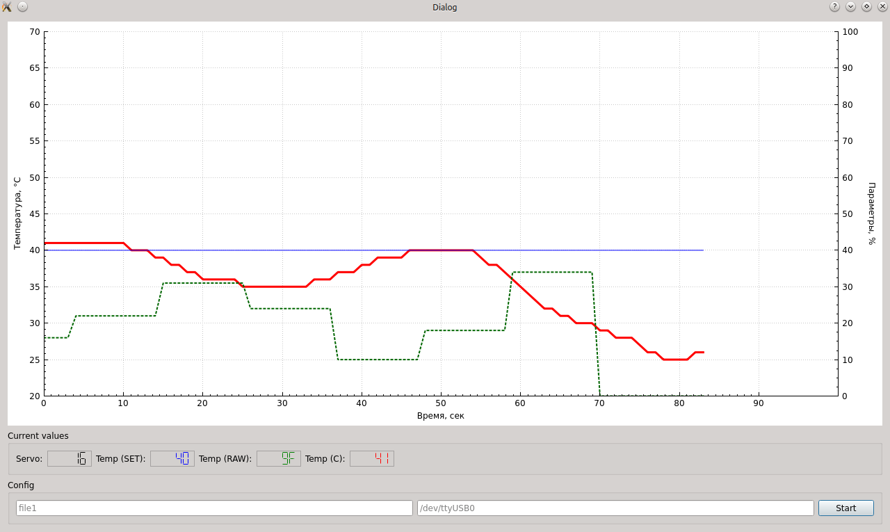
The first runs in the telemetry drawing program from the column:
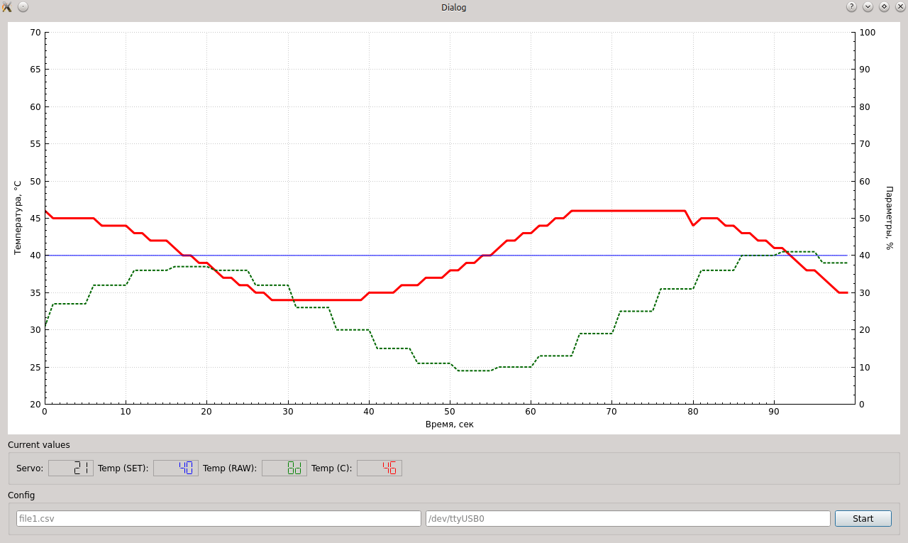
(I forgot to add a legend to the graphs. Hereinafter - red - sensor temperature, green dotted - throttle position, blue - user-desired temperature)
Almost successful adjustment.
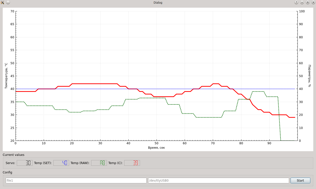
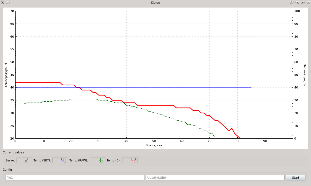
Successful options for the coefficients.
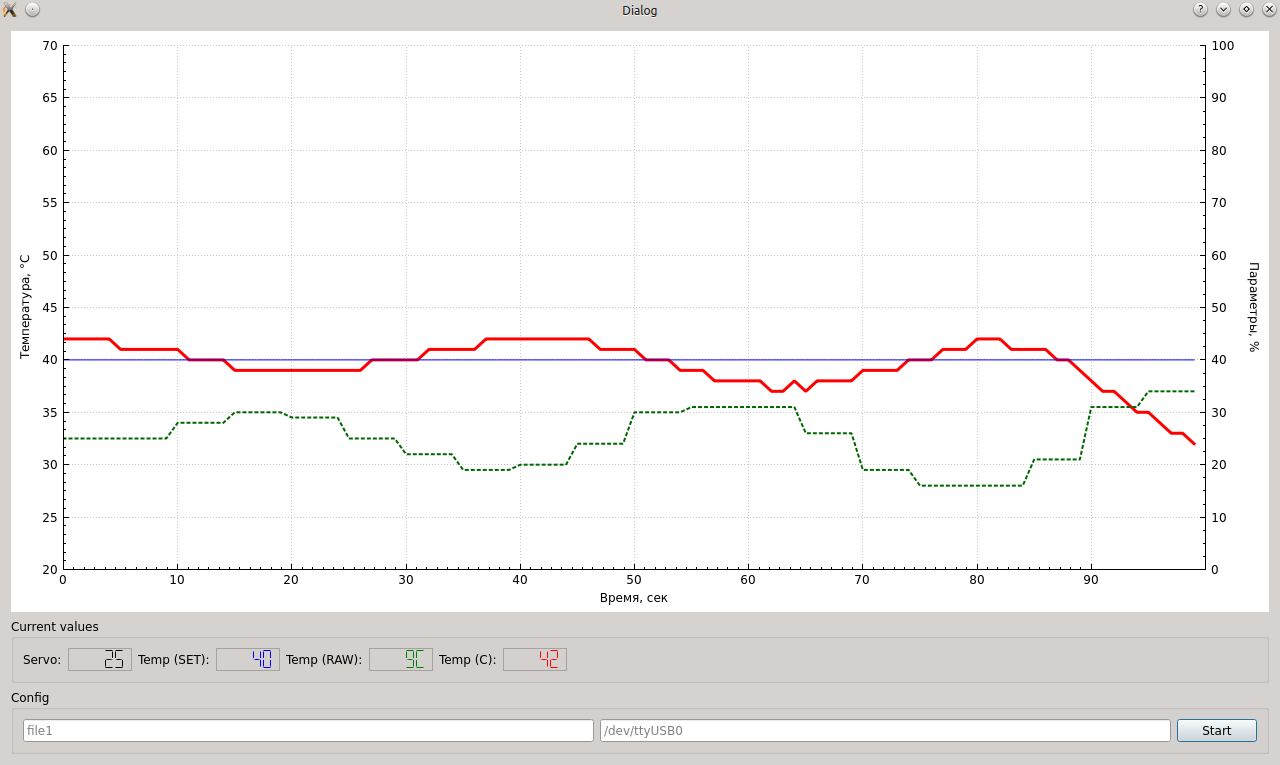
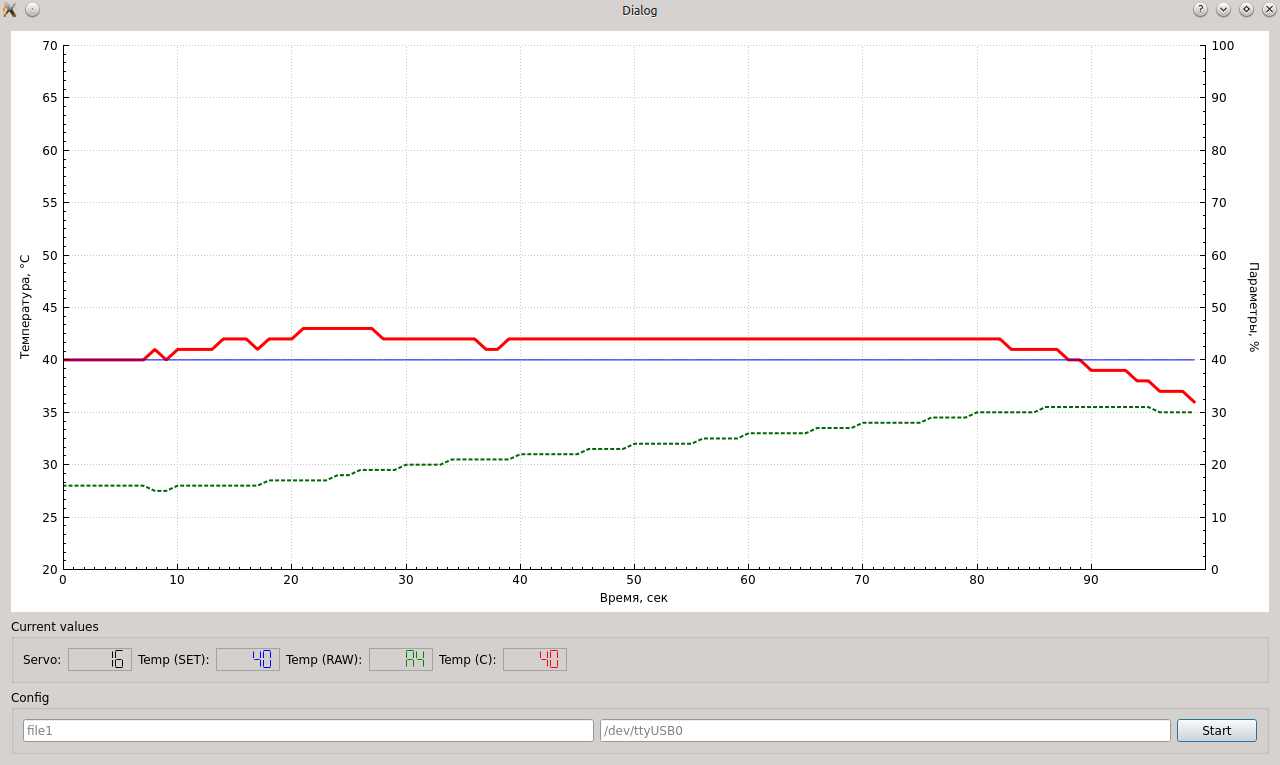
A good start option.
The first runs showed the main parameters of the system, then it was no longer difficult to measure them and adjust them according to the accelerated formula, I selected the parameters for a long time and painfully. It was not possible to completely get rid of the vibrations, but fluctuations within 1 degree are considered acceptable. Accepted option:
In the selection process, the integral coefficient had to be completely disabled, I think that this is due to the large inertia of the system. Total odds:
float Pk = 0.2;
float Ik = 0.0;
float Dk = 0.2;
5. Packaging
The device is assembled in the plastic case of the junction box.
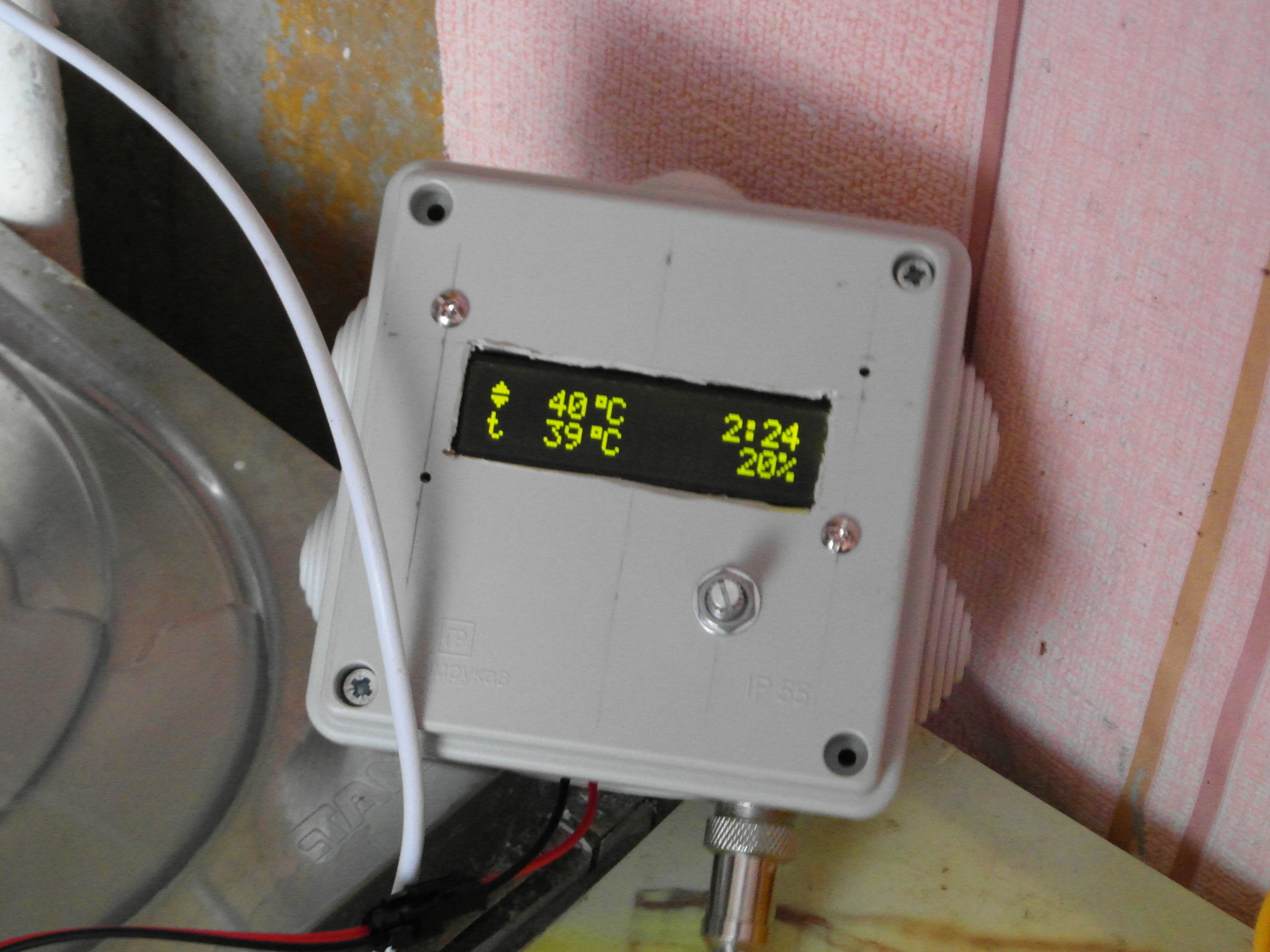
And in this form it works.
6. Safety of use
An important question that was asked from the very beginning. Let's go over the main points.
Galvanic isolation of the column and regulator circuits
What will happen if the 12V power supply is shorted and 220 volts appear on the sensor circuit? This will not cause gas to flow to the column. As it turned out - it won’t cause it - there are two levels of gas supply in the column - the electromagnetic valve of the controller and the mechanical valve of water. To open only a solenoid is not enough - gas will not enter without a current of water.
Disabling or detaching the sensor inside the HSV
When the thermistor is disconnected from the unit inside the HSV, the signal 0xFF (5.1V) will be generated at the output, which is checked by the program as an error, the controller stops the program, the servo is set to a minimum.
Disconnecting or detaching the sensor from the controller
In this case, a high temperature is generated (pulling the sensor line to the ground), which will lead to the output of the drive to the minimum value, which is also safe for the user.
Electromechanical protection of HSV
The protection values of HSV remain operational in the normal mode, in the event of boiling / overheating / column traction sensor, standard systems should disable it.
7. Files
The full project archive is available on github . In the directories of the project, measurement results, controller firmware, and a boiler on Qt are available.
Thanks for attention!