Watch networks of the past
Antique watches now, although rare, can still be found at train stations, bus stops and sometimes just on city streets. Some of them are more than half a century old, and they appeared at a time when most of the control circuits were created using relays. Nevertheless, even in such old-fashioned devices the possibility of remote configuration and synchronization was realized!
After reading the article, you will learn how the watch networks of the past were arranged and how you can revive the ancient technology using Arduino.
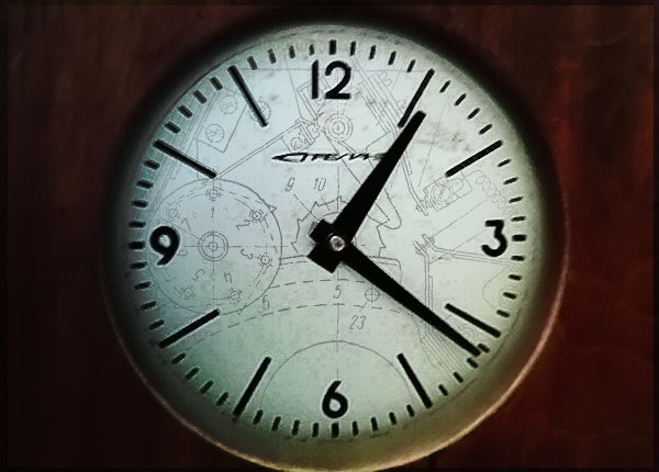
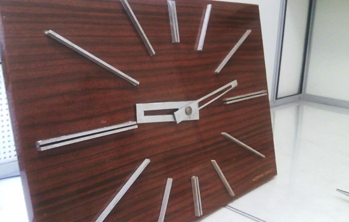
Once they turned to me with a very interesting request - to restore the functionality of an antique watch from the 60s of its release. They did not look very presentable and suspiciously resembled a cabinet door. At first glance it seemed like a makeshift craft. But in the lower right corner proudly flaunted the inscription "Arrow", which implied that the model is factory.
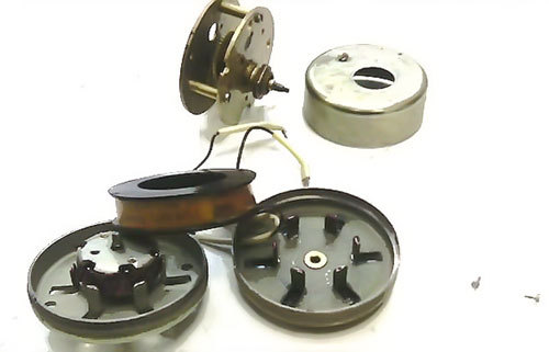
What immediately attracted attention was the mechanism, or rather, its complete absence. On the reverse side of the watch is a hand drive, which is a strange engine with a gearbox.
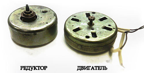
The engine, although it looks like a stepper, but has only two outputs from a single winding. The gearbox is made of brass and its gear ratio is 1:12, and so it turns out that the engine rotates the minute hand, and the hour simply follows it.
It was found experimentally that if you apply 24 volts of direct current to the motor winding, then the minute hand takes one step. When changing the polarity of the supply arrow takes another step. Obviously, the control part of this entire electromechanical system is absent. A small glance at the story will help you understand where it has gone.
In the 60s, when electronics was just getting on its feet, hybrid electromechanical clocks were used by various institutions, organizations and factories to display time. First of all, the need for them arose in the field of passenger transport - for more efficient dispatching of train, tram and bus routes.
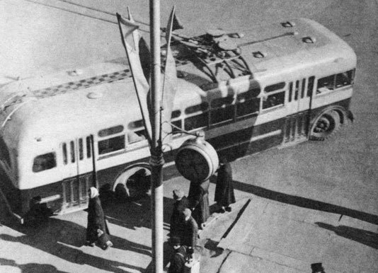
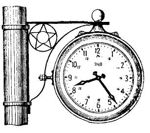
A piece of photograph S.I. Akhmerov from the 1962 photo album, Novosibirsk. The clock hanging on the post is part of the trolleybus communication system - drivers check the time against it.
It was required that several hours have the same readings, despite the fact that they could physically be quite far from each other, for example, within the transport route or in the building. This problem was solved as follows:
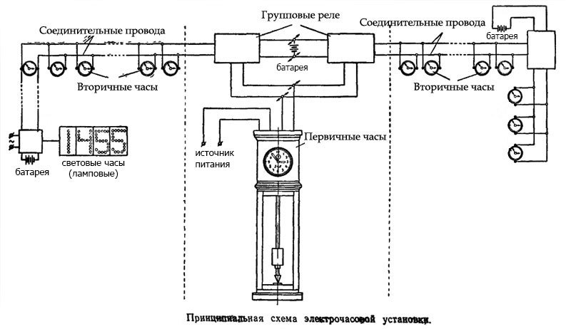
Illustration from the book of N.V. Sidorova “Operation of electric clock installations”, 1962
The picture shows almost the entire range of devices that could be part of the clock network, and as it becomes clear, I got exactly the secondary watch. The network device is quite simple: the center is the so-called electropervical clock, which once a minute produces alternating bipolar pulses. Group relays together with batteries serve as repeaters-repeaters, allowing devices to be carried over long distances. Since the current consumed by the relay winding is less than that of the clockwork drives, the losses associated with the increase in resistance in long wires will be less. Batteries are used as local power sources for the secondary watch.
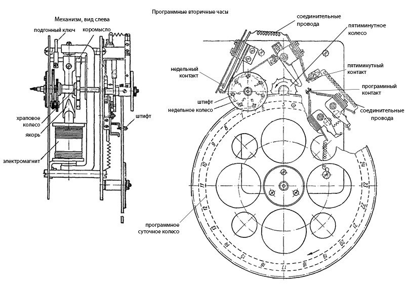
It is clear that if there is a secondary clock, then you can try to find the primary one. Unfortunately, an examination of the building where the alleged hour network was located did not yield any particular results and the tidbit of the system was not found. But in the literature of that time, the principle of their action is very well described:
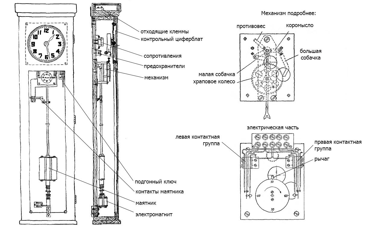
This watch is a very interesting link in the evolution of technology. They still use well-established methods of fairly accurate measurement of time intervals using oscillations of the pendulum, which is the heart of any mechanical watch. But here, this heart drives electricity. The pendulum closes the power circuit of the electromagnet approximately every few oscillations, giving it a new impulse for buildup. The rocker with which the pendulum is connected, swinging from side to side with the help of small and large dogs rotates the ratchet wheel. The meaning of this design is that in whatever direction the pendulum moves, the wheel will rotate in only one direction. It has 80 teeth, and with a period of oscillation of the pendulum equal to 1.5 seconds, makes half a revolution in one minute. Then the ebonite lever comes into play,
And the adjustable key allows you to apply pulses manually. Shaking its handle, you can change the time immediately on all the watches on the network!
Resistances in the circuit also play an important role - the designers of the past did not spare the energy spent on heating the air, because thanks to the resistance sparking on contact groups is reduced, which leads to increased reliability and durability of the device (in those days more attention was paid to these factors).
Now, having understood the principle of operation of the clock network, one could safely make a simple device emulating a primary clock, all the more so with the help of modern technologies it is as simple as that. But this story would not be complete without one more thing, which, in my opinion, turned out to be even more interesting than electric primary watches:
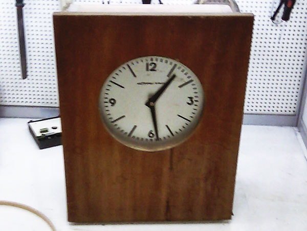
This plain-looking box turned out to be another secondary watch from the same watch network, but not as simple as the first. Inside there is a very interesting mechanism:
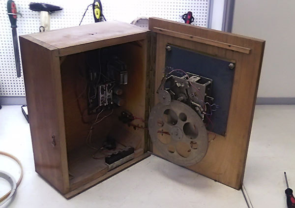
On the door behind the dial is an electromagnet that conducts the minute hand in motion. Sentinel, as in the past case, is connected with it by a gear. In addition to all this, there is a large gear, numbered from 1 to 24, and with a large number of pin holes (something like presser feet) that you can twist there. Inside the case, fuses, resistances and an old relay are fixed. Together, this forms a very intricate scheme.
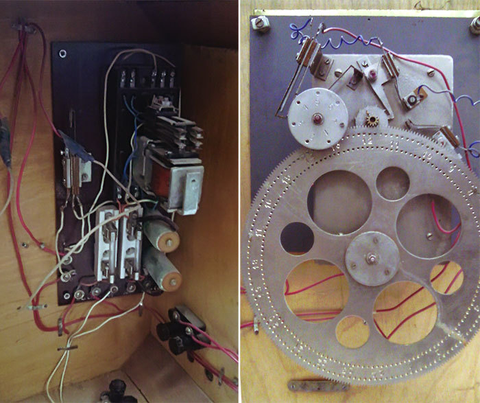
Appeal to the literature helped to understand, it is nothing more than a software clock. Using the pins screwed into the large gear, you can set the on / off time of any electrical load at a specific time.
The mechanism has its own adjustable key, which allows you to adjust the clock manually and is connected to the anchor. Depending on the polarity of the voltage on the electromagnet, the armature is attracted either one way or the other. The beam transforms translational motion into rotational motion. And the gears of the mechanism are designed so that a large software wheel makes one revolution per day, and five-minute and weekly - in accordance with their names. In the program and weekly wheels there are holes for pins, which, when turning the wheel, close the necessary contacts. The accuracy of such an "alarm" is five minutes. On the clock I got pins were installed for the time: 8:00, 12:00, 13:00 and 17:00 and for all days except Sunday. So, once this watch notified plant workers about the start of a shift, lunch and the end of the working day.
The operation of the mechanism involves closing contacts for a whole minute. Of course, such a long signal would annoy everyone, because the components in the watch case ensure the signal stops after a certain time. In accordance with the technologies of that time, a thermal group is used for this case - two contacting contacts, one of which is bimetal (in the photo to the left of the relay). When current flows through the contact, it heats up and opens due to the bending of the contact. This is another reason why accuracy is measured in minutes - the thermal group must have time to cool before the next operation. Opening time can be roughly adjusted with a tuning screw.
So, the circuit emulating the primary clock will look like this:
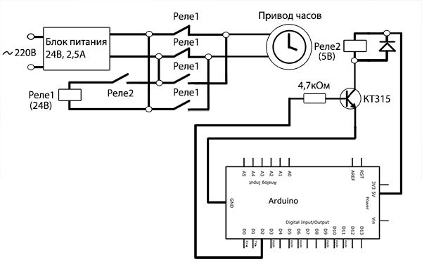
It uses a 24V DC switching power supply, two relays and, in fact, an Arduino controller. The 5V relay serves as a sort of galvanic isolation, and closes the 24-volt relay, which in turn switches the power supply to the opposite polarity. This mode of operation differs from normal, as the primary clock gave out pulses, but here the voltage is constantly supplied to the clock drive. This solution allows you to simplify the scheme without sacrificing performance.
The sketch for adruino is as simple as blinking an LED:
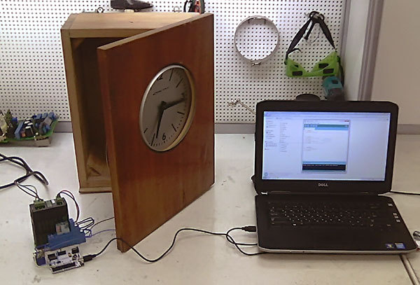
However, there are subtleties associated with the fact that the Arduino minute is not a real-time minute at all (this is due to the quartz resonator, clock cycles, as well as the inertia of the relay, and this is a completely different story), therefore it is easier to manually select the delay () value : detecting the time interval and calculating the error. Then amend the value of the trim value. In this way, I managed to set the clock with an accuracy of about a minute per day. Of course, you can do better, but this was not necessary.
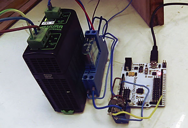
The circuit assembly: the five-volt relay has gone through a lot in its life, so I had to fill it with silicone glue.
This is good or bad, but now the watch network was not needed, so the considered watches will continue to work in the form of ordinary self-sufficient devices that everyone is used to. They will, like half a century ago, count down labor moments and serve as a reminder of a bygone era, where there were a lot of interesting things in seemingly such simple things.
After reading the article, you will learn how the watch networks of the past were arranged and how you can revive the ancient technology using Arduino.
Once they turned to me with a very interesting request - to restore the functionality of an antique watch from the 60s of its release. They did not look very presentable and suspiciously resembled a cabinet door. At first glance it seemed like a makeshift craft. But in the lower right corner proudly flaunted the inscription "Arrow", which implied that the model is factory.
What immediately attracted attention was the mechanism, or rather, its complete absence. On the reverse side of the watch is a hand drive, which is a strange engine with a gearbox.
The engine, although it looks like a stepper, but has only two outputs from a single winding. The gearbox is made of brass and its gear ratio is 1:12, and so it turns out that the engine rotates the minute hand, and the hour simply follows it.
It was found experimentally that if you apply 24 volts of direct current to the motor winding, then the minute hand takes one step. When changing the polarity of the supply arrow takes another step. Obviously, the control part of this entire electromechanical system is absent. A small glance at the story will help you understand where it has gone.
In the 60s, when electronics was just getting on its feet, hybrid electromechanical clocks were used by various institutions, organizations and factories to display time. First of all, the need for them arose in the field of passenger transport - for more efficient dispatching of train, tram and bus routes.
A piece of photograph S.I. Akhmerov from the 1962 photo album, Novosibirsk. The clock hanging on the post is part of the trolleybus communication system - drivers check the time against it.
It was required that several hours have the same readings, despite the fact that they could physically be quite far from each other, for example, within the transport route or in the building. This problem was solved as follows:
Illustration from the book of N.V. Sidorova “Operation of electric clock installations”, 1962
The picture shows almost the entire range of devices that could be part of the clock network, and as it becomes clear, I got exactly the secondary watch. The network device is quite simple: the center is the so-called electropervical clock, which once a minute produces alternating bipolar pulses. Group relays together with batteries serve as repeaters-repeaters, allowing devices to be carried over long distances. Since the current consumed by the relay winding is less than that of the clockwork drives, the losses associated with the increase in resistance in long wires will be less. Batteries are used as local power sources for the secondary watch.
It is clear that if there is a secondary clock, then you can try to find the primary one. Unfortunately, an examination of the building where the alleged hour network was located did not yield any particular results and the tidbit of the system was not found. But in the literature of that time, the principle of their action is very well described:
This watch is a very interesting link in the evolution of technology. They still use well-established methods of fairly accurate measurement of time intervals using oscillations of the pendulum, which is the heart of any mechanical watch. But here, this heart drives electricity. The pendulum closes the power circuit of the electromagnet approximately every few oscillations, giving it a new impulse for buildup. The rocker with which the pendulum is connected, swinging from side to side with the help of small and large dogs rotates the ratchet wheel. The meaning of this design is that in whatever direction the pendulum moves, the wheel will rotate in only one direction. It has 80 teeth, and with a period of oscillation of the pendulum equal to 1.5 seconds, makes half a revolution in one minute. Then the ebonite lever comes into play,
And the adjustable key allows you to apply pulses manually. Shaking its handle, you can change the time immediately on all the watches on the network!
Resistances in the circuit also play an important role - the designers of the past did not spare the energy spent on heating the air, because thanks to the resistance sparking on contact groups is reduced, which leads to increased reliability and durability of the device (in those days more attention was paid to these factors).
Now, having understood the principle of operation of the clock network, one could safely make a simple device emulating a primary clock, all the more so with the help of modern technologies it is as simple as that. But this story would not be complete without one more thing, which, in my opinion, turned out to be even more interesting than electric primary watches:
This plain-looking box turned out to be another secondary watch from the same watch network, but not as simple as the first. Inside there is a very interesting mechanism:
On the door behind the dial is an electromagnet that conducts the minute hand in motion. Sentinel, as in the past case, is connected with it by a gear. In addition to all this, there is a large gear, numbered from 1 to 24, and with a large number of pin holes (something like presser feet) that you can twist there. Inside the case, fuses, resistances and an old relay are fixed. Together, this forms a very intricate scheme.
Appeal to the literature helped to understand, it is nothing more than a software clock. Using the pins screwed into the large gear, you can set the on / off time of any electrical load at a specific time.
The mechanism has its own adjustable key, which allows you to adjust the clock manually and is connected to the anchor. Depending on the polarity of the voltage on the electromagnet, the armature is attracted either one way or the other. The beam transforms translational motion into rotational motion. And the gears of the mechanism are designed so that a large software wheel makes one revolution per day, and five-minute and weekly - in accordance with their names. In the program and weekly wheels there are holes for pins, which, when turning the wheel, close the necessary contacts. The accuracy of such an "alarm" is five minutes. On the clock I got pins were installed for the time: 8:00, 12:00, 13:00 and 17:00 and for all days except Sunday. So, once this watch notified plant workers about the start of a shift, lunch and the end of the working day.
The operation of the mechanism involves closing contacts for a whole minute. Of course, such a long signal would annoy everyone, because the components in the watch case ensure the signal stops after a certain time. In accordance with the technologies of that time, a thermal group is used for this case - two contacting contacts, one of which is bimetal (in the photo to the left of the relay). When current flows through the contact, it heats up and opens due to the bending of the contact. This is another reason why accuracy is measured in minutes - the thermal group must have time to cool before the next operation. Opening time can be roughly adjusted with a tuning screw.
So, the circuit emulating the primary clock will look like this:
It uses a 24V DC switching power supply, two relays and, in fact, an Arduino controller. The 5V relay serves as a sort of galvanic isolation, and closes the 24-volt relay, which in turn switches the power supply to the opposite polarity. This mode of operation differs from normal, as the primary clock gave out pulses, but here the voltage is constantly supplied to the clock drive. This solution allows you to simplify the scheme without sacrificing performance.
The sketch for adruino is as simple as blinking an LED:
View code
void setup () {
pinMode (2, OUTPUT); // program pin two as an output
}
void loop () {
digitalWrite (2, HIGH); // enable relay
minute (); // wait fifty seconds
delay (9535); // tuning value, approximately 9.5 sec
digitalWrite (2, LOW); // turn off the relay
minute (); // wait fifty seconds
delay (9535); // tuning value, approximately 9.5 seconds
}
void minute () {
for (int i = 1; i <= 5; i ++) {
delay (10000);
}
}
However, there are subtleties associated with the fact that the Arduino minute is not a real-time minute at all (this is due to the quartz resonator, clock cycles, as well as the inertia of the relay, and this is a completely different story), therefore it is easier to manually select the delay () value : detecting the time interval and calculating the error. Then amend the value of the trim value. In this way, I managed to set the clock with an accuracy of about a minute per day. Of course, you can do better, but this was not necessary.
The circuit assembly: the five-volt relay has gone through a lot in its life, so I had to fill it with silicone glue.
This is good or bad, but now the watch network was not needed, so the considered watches will continue to work in the form of ordinary self-sufficient devices that everyone is used to. They will, like half a century ago, count down labor moments and serve as a reminder of a bygone era, where there were a lot of interesting things in seemingly such simple things.