Resettable fuses. Myths and Reality
- Tutorial
In the comments to my last article on ways to protect against incorrect polarity of the power supplyI was repeatedly reproached for not mentioning a protection method using a resettable fuse. To correct this injustice, at first I just wanted to add an additional protection scheme and a short explanation to it in the article. However, he decided that the topic of self-healing fuses deserves a separate publication. The fact is that their well-established name does not reflect the essence of things too much, but to dig into datasheets and understand the principle of operation when using such “elementary” components as a fuse, they often start after the first batch of boards starts to fail. Well, if not serial. So, under the cut you will find an attempt to figure out what kind of animal such a PolySwitch is , the original name, by the way, better reflects the essence of the device , and understandwith what to eat it , how and in what cases it makes sense to use it.
PolySwitch is a PPTC (Polymeric Positive Temperature Coefficient) device that has a positive temperature coefficient of resistance. In truth, he has much more in common with a posistor, or a bimetallic thermal fuse, than with a fuse, with which he is usually associated not least thanks to the efforts of marketers.
The trick is in the material from which our fuse is made - it is a matrix of a non-conductive polymer mixed with carbon black. In the cold state, the polymer is crystallized, and the space between the crystals is filled with carbon particles that form many conductive chains.
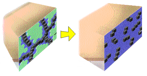
If too much current begins to flow through the fuse, it begins to heat up, and at some point in time the polymer goes into an amorphous state, increasing in size. Due to this increase, the carbon chains begin to break, which causes an increase in resistance, and the fuse heats up even faster. In the end, the fuse resistance increases so much that it begins to noticeably limit the flowing current, thus protecting the external circuit. After the device cools down, crystallization occurs and the fuse again becomes an excellent conductor.
What the temperature dependence of the resistance looks like can be seen from the following figure.
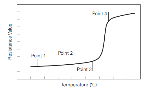
The curve indicates several points characteristic of the operation of the device. Our fuse is an excellent conductor as long as the temperature is in the operating range Point1 <T
It's time to move from theory to practice. Let's assemble a simple protection scheme for our valuable device, so simple that it would look indecent if depicted in accordance with GOST.

What will happen if an unacceptable current appears in the circuit in excess of the tripping current? The resistance of the material from which the device is made will begin to increase. This will lead to an increase in the voltage drop across it, and hence the dissipated power equal to U * I. As a result, the temperature rises, this again leads to ... In general, an avalanche-like process of heating the device begins with a simultaneous increase in resistance. As a result, the conductivity of the device drops by orders of magnitude and this leads to the desired decrease in the current in the circuit.
After the device cools down its resistance is restored. After a while, unlike a fuse with a fuse, our Ideal Fuse is ready for use again!
Is it perfect? Let's armed with our modest knowledge in the physics of the device, try to figure it out.
Perhaps the main problem is time. Time in general is such a substance that it is very difficult to defeat, although many really wanted to ... But let's not talk about politics - closer to our polymers. As you probably already guessed, I lead to the fact that the change in the crystal structure of a substance is a much longer process than the restructuring of holes with electrons, for example, in a tunnel diode. In addition, in order to warm up the device to the desired temperature, it takes some time. As a result, when the current through the fuse suddenly exceeds the threshold value, its limitation does not occur at all instantly. At currents close to the threshold, this process can take several seconds, at currents close to the maximum allowable for the device, a fraction of a second. As a result, during the operation of such protection, a complex electronic device will have time to fail, maybe not a dozen times. In support of this, I quote a typical graph of the response time (vertical) versus the current causing it (horizontal) for a hypotheticalPTVC device.
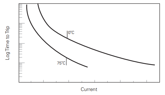
Please note that the graph shows for comparison two dependencies taken at different ambient temperatures. I hope you still remember that the primary reason for the restructuring of the crystal structure is the temperature of the material, and not the current flowing through it. This means that, ceteris paribus, in order to warm up the device to a state of metamorphosis from a lower temperature, it is necessary to spend more energy than from a higher one, which means that this process in the first case will take more time. As a result, we obtain the dependence of such important parameters of the device as the maximum guaranteed current of normal operation and guaranteed response current from the ambient temperature.
Before giving a graph, it is appropriate to mention the main technical characteristics of this class of devices.

At the bottom of the graph is the working area of the device. What will happen in the middle part depends, apparently, on the relative positions of the stars in the sky, but having visited the upper part of the graph, the device will go on a trip (trip), which will cause metamorphoses of its crystal structure and, as a result, the protection will trigger. Below is a table with the data of real devices. The difference in the tripping current depending on the temperature is impressive!

Thus, in devices designed to operate in a wide temperature range, PPTC should be used with caution. If you think that the problems for our candidate for the title of Ideal Fuse are over, then you are mistaken. He has another weakness inherent in people. After a stressful condition caused by excessive overheating, he needs to return to normal. However, hot body physics is very similar to soft physics. Like a person after a stroke, our fuse will never be the same again! To convince you, I’ll give you another schedule of the rehabilitation process after stress caused by an excess of the flowing current, which the British, aptly called, called Trip Event.and how are they not afraid of our consumer protection supervision?

The graph shows that the recovery process can last for days, but never complete. With each case of protection operation, the normal resistance of our device becomes higher and higher. After several tens of cycles, the device generally loses its ability to perform the functions assigned to it properly. Therefore, you should not use them in cases where overloads are possible with high frequency.
Perhaps it would be worthwhile to finish this, and finally start discussing the areas of application and circuit solutions, but it is worth discussing some more nuances, for which we look at the main characteristics of the widespread series of our hero of the day.

When choosing the element that you will use in the project, pay attention to the maximum allowable working current. If there is a high probability of exceeding it, then you should turn to an alternative type of protection, or limit it using another device. Well, for example, a wire resistor.
Another very important parameter is the maximum operating voltage. It is clear that when the device is in normal mode, the voltage at its contacts is very small, but after switching to protection mode, it can increase sharply. In the recent past, this parameter was very small and limited to tens of volts, which did not make it possible to use such fuses in high-voltage circuits, for example, to protect network power supplies.
Recently, the situation has improved and there are series designed for a fairly high voltage, but note that they have very small operating currents.

Judging by the variety of PolySwitch devices on the market, it is possible, and in some cases even necessary, to use them in the devices you are developing, but you should carefully approach the choice of a specific device and how to use it.
By the way, with regard to circuitry, the direct replacement of fuses on PolySwitch works well only in the simplest cases.
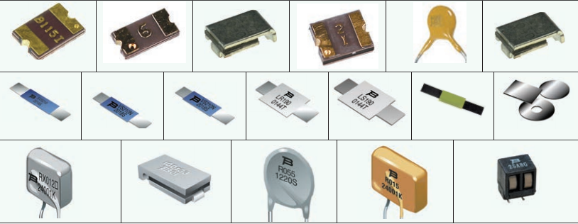
For example: for integration into battery compartments, or to protect equipment (electric motors, activators, mounting blocks) and electrical wiring in automotive applications. Those. devices that do not fail immediately when overloaded. Especially for this there is a wide class of performance of these devices in the form of jumpers with axial terminals and even disks for batteries.

In most cases, PolySwitch should be combined with faster protection devices. This approach allows you to compensate for many of their shortcomings, and as a result, they are successfully used to protect the peripheral devices of computers. In telecommunications, to protect telephone exchanges, crossovers, network equipment from surges caused by line voltage and lightning. And also when working with transformers, alarms, loudspeakers, instrumentation, satellite television and in many other cases.
Here is a simple example of protecting a USB port.

As an integrated approach, we consider a hypothetical scheme that comprehensively solves the problem of constructing an ultra-protected LED driver powered by 220V AC.

In the first stage, a self-resetting fuse is used in conjunction with a wire resistor and varistor. The varistor protects against sudden surges, and the resistor limits the current flowing in the circuit. Without this resistor, at the moment of switching on the switching power supply to the network, an unacceptably large current pulse may flow through the fuse due to the charge of the input capacities. The second stage of protection prevents reverse polarity reversal, or erroneous connection of a power supply with too high a voltage. At the same time, at the time of the emergency, the surge current takes over the protective TVS diode, and PolySwitch limits the power flowing through it, preventing thermal breakdown. By the way, this bunch is so obvious during the development of circuitry and is so widespread, that gave rise to a separate class of devices - PolyZen. A very successful hybrid of snake and quivering doe.

Well, at the output, our self-resetting fuse serves to prevent a short circuit, as well as in the event of an exit from the operating mode of the LEDs, or their driver as a result of overheating, or a malfunction.
The scheme also contains elements of protection against static, but this is not the topic of this article ...
In parting, let's briefly summarize:
ru.wikipedia.org
www.platan.ru
www.te.com
www.led-e.ru
www .terraelectronica.ru
as well as passages of knowledge from my head gleaned from various projects on the development of electronic devices , training at MIET and habits inoculated from school, to look for physical meaning in everything.
Physics of a warm body.
PolySwitch is a PPTC (Polymeric Positive Temperature Coefficient) device that has a positive temperature coefficient of resistance. In truth, he has much more in common with a posistor, or a bimetallic thermal fuse, than with a fuse, with which he is usually associated not least thanks to the efforts of marketers.
The trick is in the material from which our fuse is made - it is a matrix of a non-conductive polymer mixed with carbon black. In the cold state, the polymer is crystallized, and the space between the crystals is filled with carbon particles that form many conductive chains.
If too much current begins to flow through the fuse, it begins to heat up, and at some point in time the polymer goes into an amorphous state, increasing in size. Due to this increase, the carbon chains begin to break, which causes an increase in resistance, and the fuse heats up even faster. In the end, the fuse resistance increases so much that it begins to noticeably limit the flowing current, thus protecting the external circuit. After the device cools down, crystallization occurs and the fuse again becomes an excellent conductor.
What the temperature dependence of the resistance looks like can be seen from the following figure.
The curve indicates several points characteristic of the operation of the device. Our fuse is an excellent conductor as long as the temperature is in the operating range Point1 <T
The perfect spherical horse in a vacuum.
It's time to move from theory to practice. Let's assemble a simple protection scheme for our valuable device, so simple that it would look indecent if depicted in accordance with GOST.
What will happen if an unacceptable current appears in the circuit in excess of the tripping current? The resistance of the material from which the device is made will begin to increase. This will lead to an increase in the voltage drop across it, and hence the dissipated power equal to U * I. As a result, the temperature rises, this again leads to ... In general, an avalanche-like process of heating the device begins with a simultaneous increase in resistance. As a result, the conductivity of the device drops by orders of magnitude and this leads to the desired decrease in the current in the circuit.
After the device cools down its resistance is restored. After a while, unlike a fuse with a fuse, our Ideal Fuse is ready for use again!
Is it perfect? Let's armed with our modest knowledge in the physics of the device, try to figure it out.
It was smooth on paper, but forgot about the ravines.
Perhaps the main problem is time. Time in general is such a substance that it is very difficult to defeat, although many really wanted to ... But let's not talk about politics - closer to our polymers. As you probably already guessed, I lead to the fact that the change in the crystal structure of a substance is a much longer process than the restructuring of holes with electrons, for example, in a tunnel diode. In addition, in order to warm up the device to the desired temperature, it takes some time. As a result, when the current through the fuse suddenly exceeds the threshold value, its limitation does not occur at all instantly. At currents close to the threshold, this process can take several seconds, at currents close to the maximum allowable for the device, a fraction of a second. As a result, during the operation of such protection, a complex electronic device will have time to fail, maybe not a dozen times. In support of this, I quote a typical graph of the response time (vertical) versus the current causing it (horizontal) for a hypotheticalPTVC device.
Please note that the graph shows for comparison two dependencies taken at different ambient temperatures. I hope you still remember that the primary reason for the restructuring of the crystal structure is the temperature of the material, and not the current flowing through it. This means that, ceteris paribus, in order to warm up the device to a state of metamorphosis from a lower temperature, it is necessary to spend more energy than from a higher one, which means that this process in the first case will take more time. As a result, we obtain the dependence of such important parameters of the device as the maximum guaranteed current of normal operation and guaranteed response current from the ambient temperature.
Before giving a graph, it is appropriate to mention the main technical characteristics of this class of devices.
- The maximum operating voltage Vmax is the maximum allowable voltage that the device can withstand without breaking at rated current.
- The maximum permissible current Imax is the maximum current that the device can withstand without breaking.
- The rated operating current Ihold is the maximum current that the device can conduct without tripping, i.e. without breaking the load circuit.
- The minimum trip current Itrip is the minimum current through the device, leading to a transition from a conducting state to a non-conducting state, i.e. to trigger.
- The initial resistance Rmin, Rmax is the resistance of the device until the first operation (upon receipt from the manufacturer).
At the bottom of the graph is the working area of the device. What will happen in the middle part depends, apparently, on the relative positions of the stars in the sky, but having visited the upper part of the graph, the device will go on a trip (trip), which will cause metamorphoses of its crystal structure and, as a result, the protection will trigger. Below is a table with the data of real devices. The difference in the tripping current depending on the temperature is impressive!
Thus, in devices designed to operate in a wide temperature range, PPTC should be used with caution. If you think that the problems for our candidate for the title of Ideal Fuse are over, then you are mistaken. He has another weakness inherent in people. After a stressful condition caused by excessive overheating, he needs to return to normal. However, hot body physics is very similar to soft physics. Like a person after a stroke, our fuse will never be the same again! To convince you, I’ll give you another schedule of the rehabilitation process after stress caused by an excess of the flowing current, which the British, aptly called, called Trip Event.
The graph shows that the recovery process can last for days, but never complete. With each case of protection operation, the normal resistance of our device becomes higher and higher. After several tens of cycles, the device generally loses its ability to perform the functions assigned to it properly. Therefore, you should not use them in cases where overloads are possible with high frequency.
Perhaps it would be worthwhile to finish this, and finally start discussing the areas of application and circuit solutions, but it is worth discussing some more nuances, for which we look at the main characteristics of the widespread series of our hero of the day.
When choosing the element that you will use in the project, pay attention to the maximum allowable working current. If there is a high probability of exceeding it, then you should turn to an alternative type of protection, or limit it using another device. Well, for example, a wire resistor.
Another very important parameter is the maximum operating voltage. It is clear that when the device is in normal mode, the voltage at its contacts is very small, but after switching to protection mode, it can increase sharply. In the recent past, this parameter was very small and limited to tens of volts, which did not make it possible to use such fuses in high-voltage circuits, for example, to protect network power supplies.
Recently, the situation has improved and there are series designed for a fairly high voltage, but note that they have very small operating currents.
We cross the snake and the quivering doe.
Judging by the variety of PolySwitch devices on the market, it is possible, and in some cases even necessary, to use them in the devices you are developing, but you should carefully approach the choice of a specific device and how to use it.
By the way, with regard to circuitry, the direct replacement of fuses on PolySwitch works well only in the simplest cases.
For example: for integration into battery compartments, or to protect equipment (electric motors, activators, mounting blocks) and electrical wiring in automotive applications. Those. devices that do not fail immediately when overloaded. Especially for this there is a wide class of performance of these devices in the form of jumpers with axial terminals and even disks for batteries.
In most cases, PolySwitch should be combined with faster protection devices. This approach allows you to compensate for many of their shortcomings, and as a result, they are successfully used to protect the peripheral devices of computers. In telecommunications, to protect telephone exchanges, crossovers, network equipment from surges caused by line voltage and lightning. And also when working with transformers, alarms, loudspeakers, instrumentation, satellite television and in many other cases.
Here is a simple example of protecting a USB port.
As an integrated approach, we consider a hypothetical scheme that comprehensively solves the problem of constructing an ultra-protected LED driver powered by 220V AC.
In the first stage, a self-resetting fuse is used in conjunction with a wire resistor and varistor. The varistor protects against sudden surges, and the resistor limits the current flowing in the circuit. Without this resistor, at the moment of switching on the switching power supply to the network, an unacceptably large current pulse may flow through the fuse due to the charge of the input capacities. The second stage of protection prevents reverse polarity reversal, or erroneous connection of a power supply with too high a voltage. At the same time, at the time of the emergency, the surge current takes over the protective TVS diode, and PolySwitch limits the power flowing through it, preventing thermal breakdown. By the way, this bunch is so obvious during the development of circuitry and is so widespread, that gave rise to a separate class of devices - PolyZen. A very successful hybrid of snake and quivering doe.
Well, at the output, our self-resetting fuse serves to prevent a short circuit, as well as in the event of an exit from the operating mode of the LEDs, or their driver as a result of overheating, or a malfunction.
The scheme also contains elements of protection against static, but this is not the topic of this article ...
Forewarned is forearmed.
In parting, let's briefly summarize:
- Polyswitch is not a fuse.
- When using Polyswitch, care must be taken to ensure that the current that passes through it, even in the event of an emergency, does not exceed the permissible value. The use of current limiters is required. In some cases, elements such as connecting wires (car wiring) or internal resistance of batteries / accumulators can serve as a limiter. In such cases, the simplest circuit inclusion in the open circuit is possible.
- Polyswitch is a very inertial device, it is not suitable for protecting circuits sensitive to short surges. In these cases, it must be used in conjunction with other protection elements - zener diodes, suppressors, varistors, arresters, etc., which does not relieve you of the need to take measures to limit the maximum current in the circuit.
- When using Polyswitch, care should be taken to ensure that the voltage on it does not exceed the permissible value. High voltage may appear after the device is triggered, when its resistance increases.
- It should be remembered that the number of operations of the device is limited. After each operation, its characteristics deteriorate. It is not suitable for protecting circuits in which overloads are commonplace.
- And finally, do not forget that the operating current of this device substantially depends on the ambient temperature. The higher it is, the smaller it is. If your device is designed to operate in an extended temperature range or periodically operates in an area of elevated temperatures (a powerful power supply or bass amplifier), this can lead to a false positive.
PS
Especially in order to once again not offend the feelings of the kacang user, I want to note that during the preparation of the article materials from the following sources were used:ru.wikipedia.org
www.platan.ru
www.te.com
www.led-e.ru
www .terraelectronica.ru
as well as passages of knowledge from my head gleaned from various projects on the development of electronic devices , training at MIET and habits inoculated from school, to look for physical meaning in everything.