Arduino & OpenHAB
In a previous article, we got acquainted with the industry standard Modbus and built its support into Arduino, it remains to dock the device with the OpenHAB platform.
This time we will learn how to configure the plug-in and the OpenHAB interface to work with the device, the basics of addressing and debugging the Modbus protocol. An experiment with the source code of the plugin is presented in the work, and on the page vk.com/myremoter you can discuss the open smart home controller, which we will use in the following experiments.
But, let's see again, what advantages will the Modbus standard give us?
A modern house is a complex engineering structure, where lighting control is not the most important function. In addition to sensors, air conditioning and ventilation systems, heating control, drainage pumps and wells are installed in the house. Such tasks can be entrusted to a special or industrial controller, in which case the Modbus protocol will help to unite all engineering systems into a single network, and a simple and inexpensive controller that runs on the same bus will add additional control and functionality, saving a lot of money. In favor of this, low equipment requirements, the openness of the standard, and the widespread use of it, although perhaps the main secret of Modbus's popularity is its flexibility when docking programs and equipment.
Well, it's time to get to work.
Then install the Modbus Tcp Binding plugin which will enable OpenHAB to communicate with modbus devices. Open the download page, download Addons, unzip org.openhab.binding.modbus-1.6.2.jar into the C: \ openhab \ addons folder.
After that, configure the connection of the plug-in with the device, for this, run the OpenHAB configurator and open the openhab_default.cfg file. Find the Modbus Binding section and add the following information to the end of this section, then save the file.
Settings contain 4 groups of addresses mapped to device registers. Each group contains the serial port number, modbus address of the controller, modbus address of the first register in the group, the number of registers in the group and the type of these registers. Address groups will become the link between OpenHAB elements and the device.
Now let's configure OpenHAB connection with device registers. Open the demo.items file in the configurator and add the following code to the end of this file:
The first line defines the FF_Modbus group which will combine the added elements. Each element is set by its type, name, text label format, a list of groups in which it is composed, and communication settings with the device. We used elements of three types - Contact, Switch, Number, and in the communication settings we specified the type (modbus), the name of one of the groups specified in the plugin settings (for example, slave1) and the serial number of the register in this group.
The following table will help us visualize the relationship between the controller registers, regular and logical Modbus addresses, register groups in the plugin settings, and OpenHAB elements.
It is time to display our elements in the interface. Open the demo.sitemap file in the configurator and add a description of two frames to it:
The first frame contains the FF_Modbus group, it will display all the elements included in it.
In the second frame, each element has individual interface settings. The settings indicate the type of widget, the connection with the element and, in some cases, additional parameters. You can familiarize yourself with the principles of constructing the OpenHAB interface in this description .

Let's try to test the created configuration on the simulator.
Download the RSsim 8.19 simulator from the download page and unzip it into the C: \ arduino folder. The program has an interesting feature, it is free, and its source codes are available , but at the same time it requires registration. In the instructionsit is said that for registration you need to open the About MOD_RSsim window, click the “Register” button, enter “Completely Free” in the registration name field, and “66840713” in the registration key field.
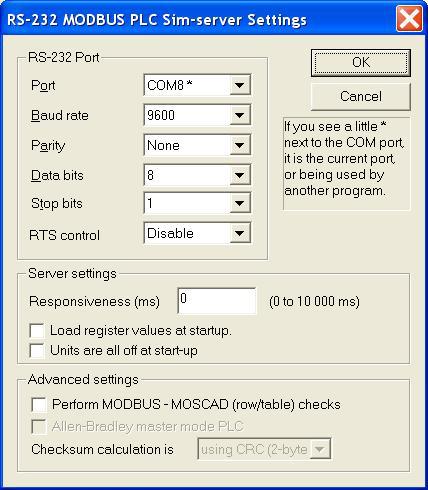
We start the simulator, perform registration, select MODBUS RS-232 in the Port field, click the button , in the serial port settings dialog indicate the second port of the virtual pair (for example, COM8), speed 9600, 1 stop bit, no parity.

We launch OpenHAB and open the web interface, click on the switches and see how the values in the Coil table of the simulator change, then open the Digital Inputs table in the simulator, change the values in the registers with addresses 10001-10004 and control the change in the state of contacts in the web interface. After that, open the Analog Inputs table, enter the values in registers 30003-30005 and control the change in the values in the INPT2-INPT4 fields. And finally, we set the values in the fields HOLD5-HOLD7 and check their compliance in the registers 40006-40008 of the simulator. You have already noticed that the simulator uses logical addressing. In order not to get completely lost in the registers, addresses and elements, use the table above.
At first glance, everything turned out, but if you look closely at the OpenHAB console, it is noticeable that with each poll of the controller, the plugin sends an event to the bus, even if nothing has changed. It seems that to solve this problem, you will have to study and modify the plugin.
The fixed plugin along with the source code is located in this repository .
We stop OpenHAB, download and copy org.openhab.binding.modbus-1.6.2.jar to the C: \ openhab \ addons folder. We launch C: \ openhab \ start.bat, open the web interface and check the operation again. Now everything is fine, events appear only when the value of the corresponding register changes.
The most interesting thing left is to check the OpenHAB interaction directly with the controller from the previous article .
We connect the controller’s USB cable to the computer, look at which port the adapter has risen (for example, COM6), stop OpenHAB, open the openhab_default.cfg file in the configurator, in the Modbus Binding section, in the communication settings for each group of registers, correct the port number (for example, modbus: serial.slave1.connection = COM6). We save the file, run OpenHAB and open the web interface. Let's try to change the value in the fields HOLD5 ... HOLD7 and CL16 ... СL18, while the value in the corresponding field INPT2..INPT4 and DT0..DT2 should change, then we will click on the layout button, and the value in the BTN field should change, click on the LED field , the LED should light up or go out.
What we got as a result of our work:
1. docked a modbus device with the OpenHAB platform;
2. got acquainted with the principles of building an interface in OpenHAB;
3. We got acquainted with the internal structure of the plugin, this allowed us to correct the inaccuracy in its work.
Conclusions:
Based on the Arduino controller and the OpenHAB platform, it is not difficult to create a software and hardware solution for automation, for example, in a Smart Home system. For further practical experiments, we try to define the main functional requirements and to the controller and the system as a whole, for this discussion to create a page open project vk.com/myremoter .
This time we will learn how to configure the plug-in and the OpenHAB interface to work with the device, the basics of addressing and debugging the Modbus protocol. An experiment with the source code of the plugin is presented in the work, and on the page vk.com/myremoter you can discuss the open smart home controller, which we will use in the following experiments.
But, let's see again, what advantages will the Modbus standard give us?
A modern house is a complex engineering structure, where lighting control is not the most important function. In addition to sensors, air conditioning and ventilation systems, heating control, drainage pumps and wells are installed in the house. Such tasks can be entrusted to a special or industrial controller, in which case the Modbus protocol will help to unite all engineering systems into a single network, and a simple and inexpensive controller that runs on the same bus will add additional control and functionality, saving a lot of money. In favor of this, low equipment requirements, the openness of the standard, and the widespread use of it, although perhaps the main secret of Modbus's popularity is its flexibility when docking programs and equipment.
Well, it's time to get to work.
Install OpenHAB, configurator and emulator of null modem connection
We will look at the documentation , open the download page and download Runtime core and Demo setup, unpack them in C: \ openhab, then download openHAB Designer and unpack it in C: \ openhab \ designer. We will check for Java by running java –version, if Java is missing, we will install it according to the instructions .
Launch OpenHAB by executing C: \ openhab \ start.bat and open the web interface using the link localhost : 8080 / openhab.app? Sitemap = demo
Now download and install com0com , launch Setup from the program menu, see what serial ports the virtual one is created for a couple (I have COM7 + COM8). We use them to communicate OpenHAB and the simulator.
Launch OpenHAB by executing C: \ openhab \ start.bat and open the web interface using the link localhost : 8080 / openhab.app? Sitemap = demo
Now download and install com0com , launch
Setup from the program menu, see what serial ports the virtual one is created for a couple (I have COM7 + COM8). We use them to communicate OpenHAB and the simulator.Then install the Modbus Tcp Binding plugin which will enable OpenHAB to communicate with modbus devices. Open the download page, download Addons, unzip org.openhab.binding.modbus-1.6.2.jar into the C: \ openhab \ addons folder.
After that, configure the connection of the plug-in with the device, for this, run the OpenHAB configurator and open the openhab_default.cfg file. Find the Modbus Binding section and add the following information to the end of this section, then save the file.
modbus:serial.slave1.connection=COM7
modbus:serial.slave1.id=1
modbus:serial.slave1.start=0
modbus:serial.slave1.length=4
modbus:serial.slave1.type=discrete
modbus:serial.slave2.connection=COM7
modbus:serial.slave2.id=1
modbus:serial.slave2.start=16
modbus:serial.slave2.length=4
modbus:serial.slave2.type=coil
modbus:serial.slave3.connection=COM7
modbus:serial.slave3.id=1
modbus:serial.slave3.start=2
modbus:serial.slave3.length=3
modbus:serial.slave3.type=input
modbus:serial.slave4.connection=COM7
modbus:serial.slave4.id=1
modbus:serial.slave4.start=5
modbus:serial.slave4.length=3
modbus:serial.slave4.type=holding
Settings contain 4 groups of addresses mapped to device registers. Each group contains the serial port number, modbus address of the controller, modbus address of the first register in the group, the number of registers in the group and the type of these registers. Address groups will become the link between OpenHAB elements and the device.
Now let's configure OpenHAB connection with device registers. Open the demo.items file in the configurator and add the following code to the end of this file:
Group	FF_Modbus 	"Modbus" 	(All)
Contact MB_DT0		"DT0 [MAP(en.map):%s]"	(FF_Modbus){modbus="slave1:0"}
Contact MB_DT1		"DT1 [MAP(en.map):%s]"	(FF_Modbus){modbus="slave1:1"}
Contact MB_DT2		"DT2 [MAP(en.map):%s]"	(FF_Modbus){modbus="slave1:2"}
Contact MB_BTN		"BTN [MAP(en.map):%s]"	(FF_Modbus){modbus="slave1:3"}
Switch  MB_CL16		"CL16" 			(FF_Modbus){modbus="slave2:0"}
Switch  MB_CL17		"CL17" 			(FF_Modbus){modbus="slave2:1"}
Switch  MB_CL18		"CL18" 			(FF_Modbus){modbus="slave2:2"}
Switch  MB_LED 	 	"LED" 			(FF_Modbus){modbus="slave2:3"}
Number  MB_INPT2	"INPT2[%d]" 		(FF_Modbus){modbus="slave3:0"}
Number  MB_INPT3	"INPT3[%d]" 		(FF_Modbus){modbus="slave3:1"}
Number  MB_INPT4	"INPT4[%d]" 		(FF_Modbus){modbus="slave3:2"}
Number  MB_HOLD5	"HOLD5[%d]" 		(FF_Modbus){modbus="slave4:0"}
Number  MB_HOLD6	"HOLD6[%d]" 		(FF_Modbus){modbus="slave4:1"}
Number  MB_HOLD7	"HOLD7[%d]" 		(FF_Modbus){modbus="slave4:2"}
The first line defines the FF_Modbus group which will combine the added elements. Each element is set by its type, name, text label format, a list of groups in which it is composed, and communication settings with the device. We used elements of three types - Contact, Switch, Number, and in the communication settings we specified the type (modbus), the name of one of the groups specified in the plugin settings (for example, slave1) and the serial number of the register in this group.
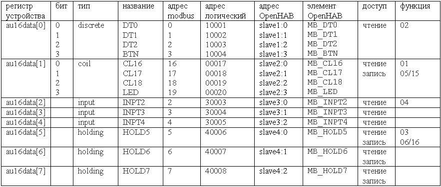
The following table will help us visualize the relationship between the controller registers, regular and logical Modbus addresses, register groups in the plugin settings, and OpenHAB elements.
It is time to display our elements in the interface. Open the demo.sitemap file in the configurator and add a description of two frames to it:
	Frame {
		Group item=FF_Modbus icon="attic"
	}
	Frame {
		Text item= MB_DT0
		Text item= MB_DT1
		Text item= MB_DT2
		Text item= MB_BTN
		Switch item= MB_CL16
		Switch item= MB_CL17
		Switch item= MB_CL18
		Switch item= MB_LED
		Text item= MB_INPT2
		Text item= MB_INPT3
		Text item= MB_INPT4
		Setpoint item= MB_HOLD5 minValue=0 maxValue=50 step=1
		Setpoint item= MB_HOLD6 minValue=0 maxValue=500 step=10
		Setpoint item= MB_HOLD7 minValue=0 maxValue=500 step=100
	}
The first frame contains the FF_Modbus group, it will display all the elements included in it.
In the second frame, each element has individual interface settings. The settings indicate the type of widget, the connection with the element and, in some cases, additional parameters. You can familiarize yourself with the principles of constructing the OpenHAB interface in this description .
Let's try to test the created configuration on the simulator.
Download the RSsim 8.19 simulator from the download page and unzip it into the C: \ arduino folder. The program has an interesting feature, it is free, and its source codes are available , but at the same time it requires registration. In the instructionsit is said that for registration you need to open the About MOD_RSsim window, click the “Register” button, enter “Completely Free” in the registration name field, and “66840713” in the registration key field.
We start the simulator, perform registration, select MODBUS RS-232 in the Port field, click the button
, in the serial port settings dialog indicate the second port of the virtual pair (for example, COM8), speed 9600, 1 stop bit, no parity.We launch OpenHAB and open the web interface, click on the switches and see how the values in the Coil table of the simulator change, then open the Digital Inputs table in the simulator, change the values in the registers with addresses 10001-10004 and control the change in the state of contacts in the web interface. After that, open the Analog Inputs table, enter the values in registers 30003-30005 and control the change in the values in the INPT2-INPT4 fields. And finally, we set the values in the fields HOLD5-HOLD7 and check their compliance in the registers 40006-40008 of the simulator. You have already noticed that the simulator uses logical addressing. In order not to get completely lost in the registers, addresses and elements, use the table above.
At first glance, everything turned out, but if you look closely at the OpenHAB console, it is noticeable that with each poll of the controller, the plugin sends an event to the bus, even if nothing has changed. It seems that to solve this problem, you will have to study and modify the plugin.
Solution Description
Brief information on the architecture of the OpenHAB plugin can be found here .
OpenHAB development environment setup issues are reflected in this guide .
In the process, the changes affected the two files ModbusGenericBindingProvider.java and ModbusBinding.java.
ModbusGenericBindingProvider contains a nested class ModbusBindingConfig that stores the configuration of the element; we create a mechanism for saving the current state in it.
Add a variable to this class
Fix the function code
And add a function
The ModbusBinding class contains two methods:
These methods are called each time after polling the slave. Let's correct their code in such a way as to send an event only if the data has changed.
OpenHAB development environment setup issues are reflected in this guide .
In the process, the changes affected the two files ModbusGenericBindingProvider.java and ModbusBinding.java.
ModbusGenericBindingProvider contains a nested class ModbusBindingConfig that stores the configuration of the element; we create a mechanism for saving the current state in it.
Add a variable to this class
private State mb_itemState = UnDefType.NULL;Fix the function code
State getItemState() {
	return mb_itemState;
}
And add a function
void setItemState(State state) {
	mb_itemState = state;
}
The ModbusBinding class contains two methods:
protected void internalUpdateItem(String slaveName, InputRegister[] registers, String itemName)protected void internalUpdateItem(String slaveName, BitVector coils, String itemName)These methods are called each time after polling the slave. Let's correct their code in such a way as to send an event only if the data has changed.
protected void internalUpdateItem(String slaveName, InputRegister[] registers,String itemName) {
	for (ModbusBindingProvider provider : providers) {
		if ( !provider.providesBindingFor(itemName) ) {
			continue;
		}
		ModbusBindingConfig config = provider.getConfig(itemName);
		if ( !config.slaveName.equals(slaveName)) {
			continue;
		}
		String slaveValueType = modbusSlaves.get(slaveName).getValueType();
		double rawDataMultiplier = modbusSlaves.get(slaveName).getRawDataMultiplier();
		State newState = extractStateFromRegisters(registers, config.readRegister, slaveValueType);
		/* receive data manipulation */
		if (config.getItem() instanceof SwitchItem) {
			newState = newState.equals(DecimalType.ZERO) ? OnOffType.OFF : OnOffType.ON;
		}
		if (( rawDataMultiplier != 1 ) && (config.getItem() instanceof NumberItem)) {
			double tmpValue = (double)((DecimalType)newState).doubleValue() * rawDataMultiplier;
			newState =  new DecimalType( String.valueOf(tmpValue) );
		}
		State currentState = config.getItemState();
		if (! newState.equals(currentState)) {
			eventPublisher.postUpdate(itemName, newState);
			config.setItemState(newState); //!!!
		}
	}
}
protected void internalUpdateItem(String slaveName, BitVector coils, String itemName) {
	for (ModbusBindingProvider provider : providers) {
		if (provider.providesBindingFor(itemName)) {
			ModbusBindingConfig config = provider.getConfig(itemName);
			if (config.slaveName.equals(slaveName)) {
				boolean state = coils.getBit(config.readRegister);
				State currentState = provider.getConfig(itemName).getItemState();
				State newState = provider.getConfig(itemName).translateBoolean2State(state);
				if (!newState.equals(currentState)) {
					eventPublisher.postUpdate(itemName, newState);
					config.setItemState(newState); //!!!
				}
			}
		}
	}
}
The fixed plugin along with the source code is located in this repository .
We stop OpenHAB, download and copy org.openhab.binding.modbus-1.6.2.jar to the C: \ openhab \ addons folder. We launch C: \ openhab \ start.bat, open the web interface and check the operation again. Now everything is fine, events appear only when the value of the corresponding register changes.
The most interesting thing left is to check the OpenHAB interaction directly with the controller from the previous article .
We connect the controller’s USB cable to the computer, look at which port the adapter has risen (for example, COM6), stop OpenHAB, open the openhab_default.cfg file in the configurator, in the Modbus Binding section, in the communication settings for each group of registers, correct the port number (for example, modbus: serial.slave1.connection = COM6). We save the file, run OpenHAB and open the web interface. Let's try to change the value in the fields HOLD5 ... HOLD7 and CL16 ... СL18, while the value in the corresponding field INPT2..INPT4 and DT0..DT2 should change, then we will click on the layout button, and the value in the BTN field should change, click on the LED field , the LED should light up or go out.
What we got as a result of our work:
1. docked a modbus device with the OpenHAB platform;
2. got acquainted with the principles of building an interface in OpenHAB;
3. We got acquainted with the internal structure of the plugin, this allowed us to correct the inaccuracy in its work.
Conclusions:
Based on the Arduino controller and the OpenHAB platform, it is not difficult to create a software and hardware solution for automation, for example, in a Smart Home system. For further practical experiments, we try to define the main functional requirements and to the controller and the system as a whole, for this discussion to create a page open project vk.com/myremoter .