We collect the glove to determine the position of the hands ourselves
- Tutorial
In this article I will talk about how we collected the glove to determine the position of the hand for the contest. Of course, there are difficulties in its manufacture, but even a schoolboy can assemble it. Such a glove can be used both for controlling electronics and as a manipulator for various games.
Those who read the scanner articleprobably remember that I promised continuation. But because of the competitions, I still have no time for this. But now I am sitting after the competition and writing an article about part of our project. At the exhibition, I was asked to talk about the principle of operation of this device, then they asked for contacts, and then I just decided that I would better write an article and solve the problem of more than two people. Initially, using this glove, we controlled electronics (we turned on kettles on the Internet using gestures), but now we use it to track the position of the hand. That's the whole introduction.
Gesture gloves can be divided into several types (I can skip something):
1) On strain gages
Well, this is the easiest. A strain gauge is such a strip from which two contacts extend. When stretching / compressing a given strip, its resistance changes. We put on each movable joint with such a sensor and get a profit. But these strain gages are quite expensive, you can not determine the direction of the bend and the tape itself has a decent length (about the length of a finger).
2) On the "LED tubes"
Already more interesting. The bottom line is this: a silicone or rubber tube is taken, an LED is installed at one end of the tube, and a photoresistor / transistor at the other end. The stronger we bend such a sensor, the less light enters the photosensor, and accordingly its resistance increases. Such a sensor costs an order of magnitude cheaper. But it has the same disadvantages: it is inconvenient to bend and you cannot determine the direction of the bend.
3) Orientation sensors
By this I mean various accelerometers, gyroscopes, magnetometers and their various combinations. The cost of such sensors varies enormously, and the main problems arise during their programming. These are the sensors I used with a glove.
I opted for the LIS331 sensors. This is an eight-bit three-axis accelerometer. Just because they were then worth 30 rubles apiece at retail. In general, this was my first experience in using such sensors, so I decided: "if I ditch this sensor, then I won’t be sorry."
From the accelerometer we get the decomposition of the acceleration vector of the sensor along its three axes. Where does the acceleration come from? Well, as from space - the acceleration of free fall of the Earth affects us. Here it must be said about the minus of this sensor: this same vector fluctuates from any hand shake, so that we have high-frequency interference at the output. But to determine the gesture, when the hand is almost not moving, they can be used.
Actually, this is the whole task: take a sensor for each movable bone, connect it to the microcontroller, find the position of the sensor, determine the gesture. But it was not there…
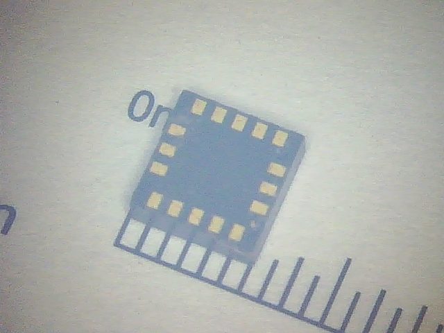
To begin with, this sensor still needs to be soldered. Do you think you solder well? Meet (grid pitch in the photo 0.5 mm):
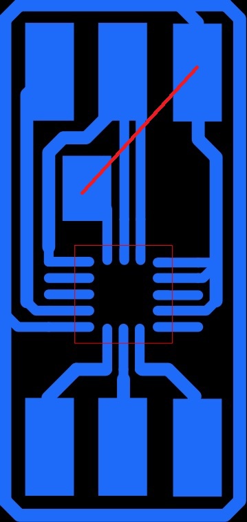
LGA16. He is also pleased to meet you. It was because of him that I had to buy a soldering station. I really love SMD. Details are small and scarves, respectively, also come out small. But this is ... In general, now, after soldering the MPU-9250, I say that it is a freebie, and then it was an adish. Well, at least kill is not a pity. Armed with a program for tracing boards, draw a board. First, a pad for the chip. Our best friend when soldering is surface tension. When we solder, it is this force that will make the microcircuit fall into place. Therefore, the sites need to be made quite long, otherwise the microcircuit will pull the same surface tension to the side. We take all sizes from a datasheet. I couldn’t do it in one layer without jumpers, so one still will. On the wiring, it is shown by the red line. Large areas in order to solder a loop there. Since the pitch between these pads is 2.54 mm and these pads are located both above and below the microcircuit, a loop with a pitch between wiring of 1.27 mm is ideally suited to us. The result is this board:
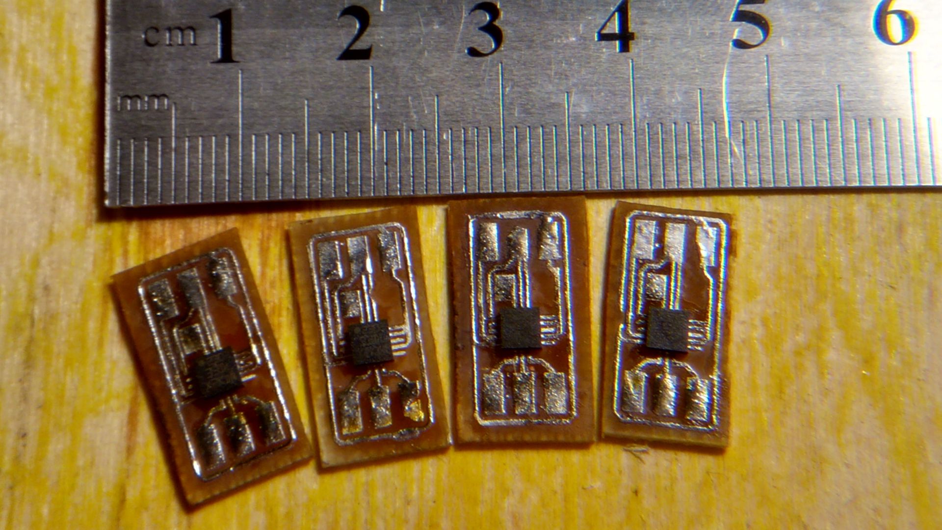
And here is such a sensor after soldering:
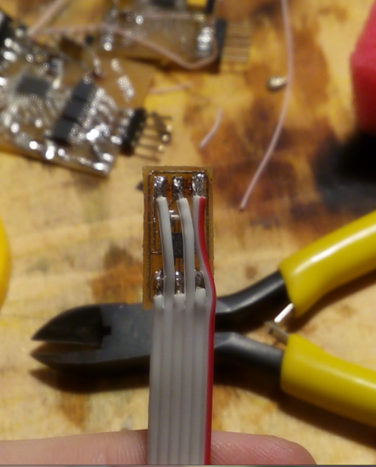
The photo clearly shows themess on the table for which I apologize for what I had in mind when I spoke about the step of the conclusions. The width of the loop is almost equal to the width of the board, and therefore does not look quite bad. But the board still needs to be made and etched. The fee is easily made by LUT, and I am poisoning in hydrogen peroxide. To achieve the best result, I roll a board in a solution using an electric motor. You can immediately make an array of circuit boards on one piece of fiberglass. This will significantly speed up the manufacturing process. After etching, we get a fee and at this stage the problems begin ...
This process is completely useless to describe. It’s better to see the video once. I’ll just say that I squeezed 8 sensors before I soldered the 6 sensors I needed. Well, the first time I solder this, you can forgive. I will not attach the video about soldering the LGA case, since they are easy to find in the search engine, and I don’t want to clog the Internet with the next.
Another useful life hack: solder with a hairdryer in some tray / baking sheet / plate / basin in general in anything that has sides. Microchips are blown away by a hairdryer, and looking for them is almost useless.
After sealing the sensor, we solder the loop, remember that we forgot to solder the jumper, unsolder the loop, solder the jumper, return the loop to its place.
It's up to you which MK to use. Here I will tell you about a little trick, about which for some reason they forget. And it allows you to save the legs of the microcontroller, which on some boards is already not enough. And this trick is called logic. Not the one that happens to be female, but the one that starts at 74HC. We are specifically interested in the 74HC164. This is a shift register. It works quite simply. He has legs Data, Clock, Reset and conclusions. Through Data and Clock, we sequentially transmit 8 bits, which the register simultaneously outputs to conclusions. And with the help of Reset, you can set all the outputs to 0. Actually we connect the Enable accelerometer legs to this microcircuit and with the help of one microcircuit we control eight accelerometers. But we only need five, so the remaining two can be occupied by LEDs. It will be a beautiful highlight. But there is a bug here: when we reset the microcircuit, 0. will be written in the “bit of LEDs”. And since we are writing data rather quickly, this blinking will look like a decrease in brightness, which can make the engineer nervous. Actually, the general block diagram of the glove will look like this:
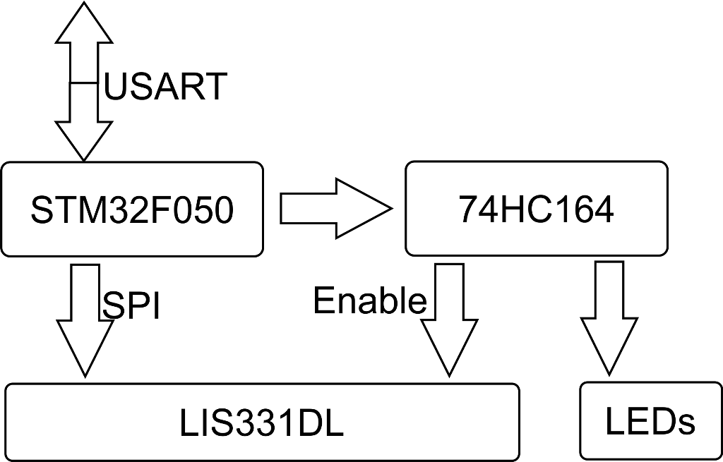
When programming, you must also remember that the microcircuit will be selected when there is a logical zero on the Enable leg (aka CS). So in order to select the second accelerometer, it will be necessary to write in the register not 01000000, but 10111111.
Data exchange with the accelerometer occurs as follows:
0 bit - R / W bit. If 1, then we read the data, if 0, then we write to the sensor.
1-7 bit - The address of the register with which we are going to work.
8-15 bit - Data that we write in the register. If we read, then the accelerometer will simply ignore them.
If everything is clear with this, then for a start we read the register WHO_AM_I. This register can only be read and its default value can be found in the datasheet. For our accelerometer, this register is located at 0x0F, and the default value is 0x3B. That is, we send 0x8F first to the accelerometer, then any 8 bits, and 0x3B should be considered. If you read something else, then somewhere a jamb. Either in soldering, or sending the wrong data, or overheating the chip during soldering. Maybe the speed is too high. And do not forget to pull the CS leg to the ground and return it back. If you have received the correct data, then you can be congratulated - it remains to solder only 4 sensors. You get the following picture:
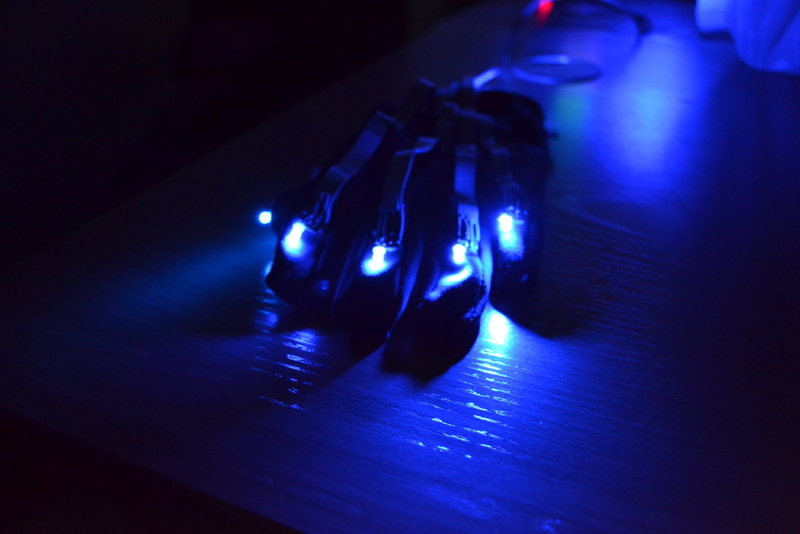
After sealing all five sensors (one for each finger), we attach them to the glove. I used hot glue for this. This is what happened:

In order for us to start receiving any data from the microcircuit, it must be turned on. To do this, set the BOOT bit of the CTRL_REG2 register to a unit and write 0xC7 to the CTRL_REG1 register. The first is a reboot of the accelerometer, and the second is the output of the sensor from the power saving mode, the setting of the sampling frequency of 400Hz, and the inclusion of all three axes.
All data from the x, y, and z axes is written into registers with addresses 0x29, 0x2B, and 0x2D, respectively. In order to get the data, we just read it and that’s it (do not forget that if we read, then 0bit of the first sending is 1). Here's another “if” with a catch: if you read the data, and there are solid zeros, and the code is definitely working and correct, then look carefully at the name of your accelerometers. There may be not LIS331DL, but LIS331DLH. What does this letter give? And the sensor is now 16-bit, so also with a lot of settings. Because of this, the addresses of the registers are changing. I killed 4 hours to find this jamb, no less. It was a shame. But suppose you did everything right. Then you get such trash in the terminal:

I doubt that such accelerations act on the accelerometer peacefully lying on the table. Probably the whole thing is interference. No, well, what did we want for 30 rubles? We will have to somehow get rid of them. For this we need a filter. The easiest way to implement it is software (inside the sensor it seems like there is a filter, but for some reason it didn’t work for me). It looks ugly simply: new value = old value + measured value * coefficient. It is clear that the cutoff frequency depends on the coefficient that you need to choose for your own tasks.
In the simplest case, you can just look at the sign of the number that we have accepted. Get an array of five fingers, and send this array to the computer. Like, if the finger is bent, then 1, and if it is straightened, then 0. For example, 11011. This is exactly what was implemented in the first glove, because more was not required. But it is quite realistic to determine the angle of inclination. To do this, we simply take the arctangent of the ratio of accelerations along two axes and get the angle of inclination along the plane in which these axes lie. Having done this for three pairs of axes, we can find the tilt angles along three axes and restore the position of the sensor in three-dimensional space. But, I think, nobody will need it. Not even because the task will not require it, but because for such tasks you need to use a six-axis sensor (accelerometer + gyroscope) or even better nine-axis (accelerometer + gyroscope + magnetometer).
I hope that those who wanted to collect something like this article will help. I would have helped at that time. Now we have already won one competition with this glove, and even made a new glove on nine-axis sensors, with which we won on the other. True, I’ll tell you in secret that the magnetometer didn’t work for me, but nobody knows about it. The glove works pretty well even without it, so I'd rather buy cheaper six-axis sensors. Now contests are not expected in the near future, so I will try to write the second article about the 3d scanner, as I promised.
PS I forgot to actually attach the board layout for the sensor:
Board in SprintLayout
Those who read the scanner articleprobably remember that I promised continuation. But because of the competitions, I still have no time for this. But now I am sitting after the competition and writing an article about part of our project. At the exhibition, I was asked to talk about the principle of operation of this device, then they asked for contacts, and then I just decided that I would better write an article and solve the problem of more than two people. Initially, using this glove, we controlled electronics (we turned on kettles on the Internet using gestures), but now we use it to track the position of the hand. That's the whole introduction.
Principle of operation
Gesture gloves can be divided into several types (I can skip something):
1) On strain gages
Well, this is the easiest. A strain gauge is such a strip from which two contacts extend. When stretching / compressing a given strip, its resistance changes. We put on each movable joint with such a sensor and get a profit. But these strain gages are quite expensive, you can not determine the direction of the bend and the tape itself has a decent length (about the length of a finger).
2) On the "LED tubes"
Already more interesting. The bottom line is this: a silicone or rubber tube is taken, an LED is installed at one end of the tube, and a photoresistor / transistor at the other end. The stronger we bend such a sensor, the less light enters the photosensor, and accordingly its resistance increases. Such a sensor costs an order of magnitude cheaper. But it has the same disadvantages: it is inconvenient to bend and you cannot determine the direction of the bend.
3) Orientation sensors
By this I mean various accelerometers, gyroscopes, magnetometers and their various combinations. The cost of such sensors varies enormously, and the main problems arise during their programming. These are the sensors I used with a glove.
I opted for the LIS331 sensors. This is an eight-bit three-axis accelerometer. Just because they were then worth 30 rubles apiece at retail. In general, this was my first experience in using such sensors, so I decided: "if I ditch this sensor, then I won’t be sorry."
From the accelerometer we get the decomposition of the acceleration vector of the sensor along its three axes. Where does the acceleration come from? Well, as from space - the acceleration of free fall of the Earth affects us. Here it must be said about the minus of this sensor: this same vector fluctuates from any hand shake, so that we have high-frequency interference at the output. But to determine the gesture, when the hand is almost not moving, they can be used.
Actually, this is the whole task: take a sensor for each movable bone, connect it to the microcontroller, find the position of the sensor, determine the gesture. But it was not there…
Sensor Board
To begin with, this sensor still needs to be soldered. Do you think you solder well? Meet (grid pitch in the photo 0.5 mm):
LGA16. He is also pleased to meet you. It was because of him that I had to buy a soldering station. I really love SMD. Details are small and scarves, respectively, also come out small. But this is ... In general, now, after soldering the MPU-9250, I say that it is a freebie, and then it was an adish. Well, at least kill is not a pity. Armed with a program for tracing boards, draw a board. First, a pad for the chip. Our best friend when soldering is surface tension. When we solder, it is this force that will make the microcircuit fall into place. Therefore, the sites need to be made quite long, otherwise the microcircuit will pull the same surface tension to the side. We take all sizes from a datasheet. I couldn’t do it in one layer without jumpers, so one still will. On the wiring, it is shown by the red line. Large areas in order to solder a loop there. Since the pitch between these pads is 2.54 mm and these pads are located both above and below the microcircuit, a loop with a pitch between wiring of 1.27 mm is ideally suited to us. The result is this board:
And here is such a sensor after soldering:
The photo clearly shows the
Soldering
This process is completely useless to describe. It’s better to see the video once. I’ll just say that I squeezed 8 sensors before I soldered the 6 sensors I needed. Well, the first time I solder this, you can forgive. I will not attach the video about soldering the LGA case, since they are easy to find in the search engine, and I don’t want to clog the Internet with the next.
Another useful life hack: solder with a hairdryer in some tray / baking sheet / plate / basin in general in anything that has sides. Microchips are blown away by a hairdryer, and looking for them is almost useless.
After sealing the sensor, we solder the loop, remember that we forgot to solder the jumper, unsolder the loop, solder the jumper, return the loop to its place.
Microcontroller board
It's up to you which MK to use. Here I will tell you about a little trick, about which for some reason they forget. And it allows you to save the legs of the microcontroller, which on some boards is already not enough. And this trick is called logic. Not the one that happens to be female, but the one that starts at 74HC. We are specifically interested in the 74HC164. This is a shift register. It works quite simply. He has legs Data, Clock, Reset and conclusions. Through Data and Clock, we sequentially transmit 8 bits, which the register simultaneously outputs to conclusions. And with the help of Reset, you can set all the outputs to 0. Actually we connect the Enable accelerometer legs to this microcircuit and with the help of one microcircuit we control eight accelerometers. But we only need five, so the remaining two can be occupied by LEDs. It will be a beautiful highlight. But there is a bug here: when we reset the microcircuit, 0. will be written in the “bit of LEDs”. And since we are writing data rather quickly, this blinking will look like a decrease in brightness, which can make the engineer nervous. Actually, the general block diagram of the glove will look like this:
When programming, you must also remember that the microcircuit will be selected when there is a logical zero on the Enable leg (aka CS). So in order to select the second accelerometer, it will be necessary to write in the register not 01000000, but 10111111.
Programming
Data exchange with the accelerometer occurs as follows:
0 bit - R / W bit. If 1, then we read the data, if 0, then we write to the sensor.
1-7 bit - The address of the register with which we are going to work.
8-15 bit - Data that we write in the register. If we read, then the accelerometer will simply ignore them.
If everything is clear with this, then for a start we read the register WHO_AM_I. This register can only be read and its default value can be found in the datasheet. For our accelerometer, this register is located at 0x0F, and the default value is 0x3B. That is, we send 0x8F first to the accelerometer, then any 8 bits, and 0x3B should be considered. If you read something else, then somewhere a jamb. Either in soldering, or sending the wrong data, or overheating the chip during soldering. Maybe the speed is too high. And do not forget to pull the CS leg to the ground and return it back. If you have received the correct data, then you can be congratulated - it remains to solder only 4 sensors. You get the following picture:
After sealing all five sensors (one for each finger), we attach them to the glove. I used hot glue for this. This is what happened:
In order for us to start receiving any data from the microcircuit, it must be turned on. To do this, set the BOOT bit of the CTRL_REG2 register to a unit and write 0xC7 to the CTRL_REG1 register. The first is a reboot of the accelerometer, and the second is the output of the sensor from the power saving mode, the setting of the sampling frequency of 400Hz, and the inclusion of all three axes.
All data from the x, y, and z axes is written into registers with addresses 0x29, 0x2B, and 0x2D, respectively. In order to get the data, we just read it and that’s it (do not forget that if we read, then 0bit of the first sending is 1). Here's another “if” with a catch: if you read the data, and there are solid zeros, and the code is definitely working and correct, then look carefully at the name of your accelerometers. There may be not LIS331DL, but LIS331DLH. What does this letter give? And the sensor is now 16-bit, so also with a lot of settings. Because of this, the addresses of the registers are changing. I killed 4 hours to find this jamb, no less. It was a shame. But suppose you did everything right. Then you get such trash in the terminal:
I doubt that such accelerations act on the accelerometer peacefully lying on the table. Probably the whole thing is interference. No, well, what did we want for 30 rubles? We will have to somehow get rid of them. For this we need a filter. The easiest way to implement it is software (inside the sensor it seems like there is a filter, but for some reason it didn’t work for me). It looks ugly simply: new value = old value + measured value * coefficient. It is clear that the cutoff frequency depends on the coefficient that you need to choose for your own tasks.
Gesture definition
In the simplest case, you can just look at the sign of the number that we have accepted. Get an array of five fingers, and send this array to the computer. Like, if the finger is bent, then 1, and if it is straightened, then 0. For example, 11011. This is exactly what was implemented in the first glove, because more was not required. But it is quite realistic to determine the angle of inclination. To do this, we simply take the arctangent of the ratio of accelerations along two axes and get the angle of inclination along the plane in which these axes lie. Having done this for three pairs of axes, we can find the tilt angles along three axes and restore the position of the sensor in three-dimensional space. But, I think, nobody will need it. Not even because the task will not require it, but because for such tasks you need to use a six-axis sensor (accelerometer + gyroscope) or even better nine-axis (accelerometer + gyroscope + magnetometer).
Conclusion
I hope that those who wanted to collect something like this article will help. I would have helped at that time. Now we have already won one competition with this glove, and even made a new glove on nine-axis sensors, with which we won on the other. True, I’ll tell you in secret that the magnetometer didn’t work for me, but nobody knows about it. The glove works pretty well even without it, so I'd rather buy cheaper six-axis sensors. Now contests are not expected in the near future, so I will try to write the second article about the 3d scanner, as I promised.
PS I forgot to actually attach the board layout for the sensor:
Board in SprintLayout