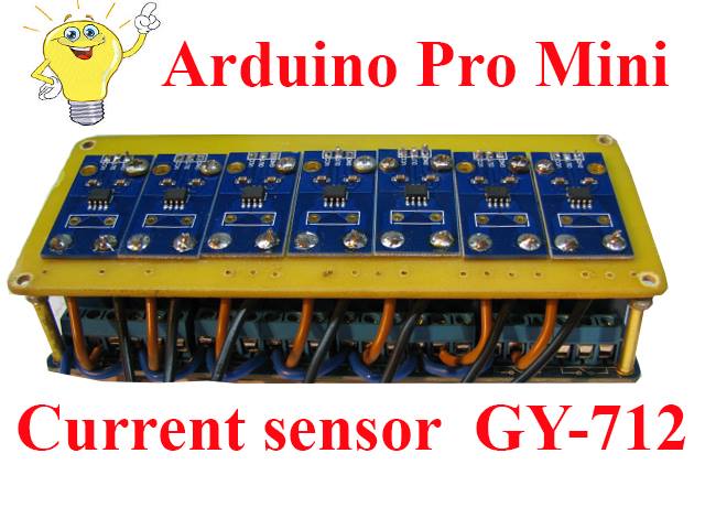
Arduino Pro Mini + current sensor GY-712 conduct lamp burnout control
Hello. I want to share one of the projects created on the basis of Arduino.
For me, working with current sensors GY-712 was the first time. Before creating this project, a test block was created.
If you are already interested, then continue.
Here I will talk about one module, because describing and sketching 7 modules is not very easy.
There was a task:
1) Lamps (lanterns) 50-65VT 220V changeover or 24V constant;
2) Indication of lamp operation (LED on the panel);
3) Sound indication of a blown lamp.
The decision was made as follows:
We use a current sensor GY-712 5A
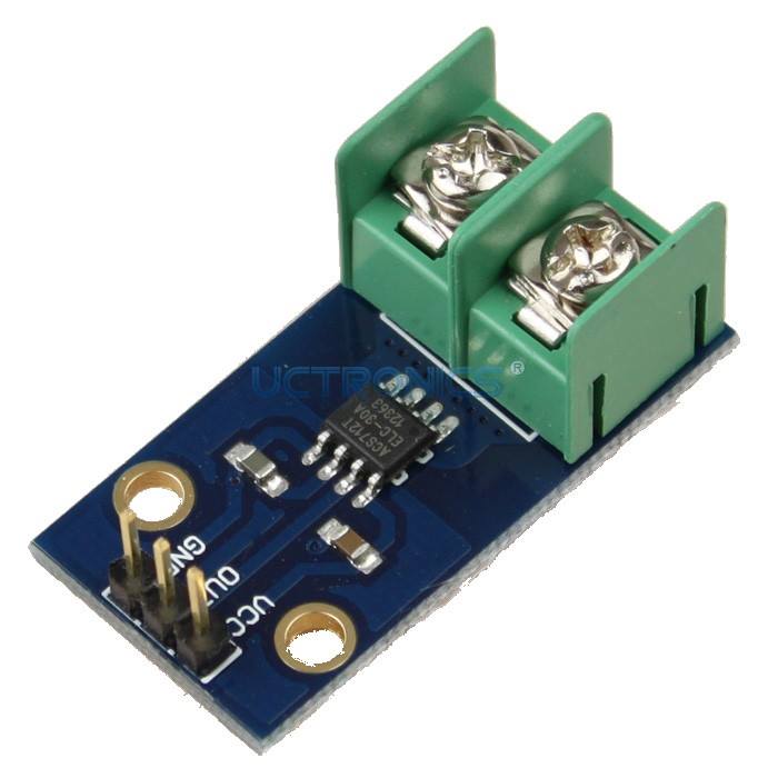
For reasons:
1) Measures AC and DC current;
2) Easy to connect to the controller;
3) Compact;
4) Inexpensive when ordering from China.
Let's look at the diagram:
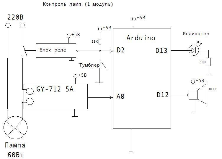
How the program works.
At start, it checks whether the toggle switch is on, if it is on, you will hear an audio signal and a light indication so that the sensor can be calibrated without load. If you turn off the toggle switch, the program will give a sound + indication.
Next is the calibration. After calibration - a sound signal.
And the main program starts. Toggle switch control, if enabled, then control the lamp load current, if the current is above a predetermined threshold, then turn on the display; if there is no current, turn off the display and give a sound signal.
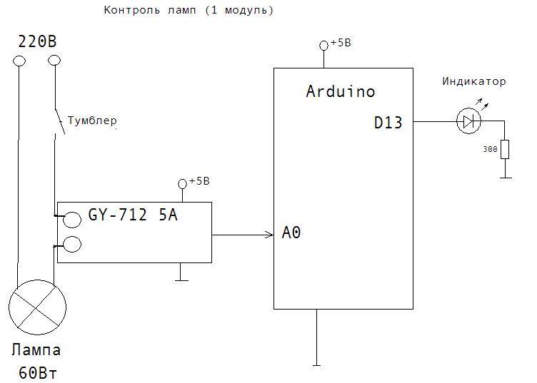
Here is a simple diagram without toggle switch control, just a light indication. This is just in case anyone who just needs a load indicator light - but then you can just wind the wires around the ferrite ring (make a current transformer) and connect an LED.
Test photos:


Test video:
For me, working with current sensors GY-712 was the first time. Before creating this project, a test block was created.
If you are already interested, then continue.
Here I will talk about one module, because describing and sketching 7 modules is not very easy.
There was a task:
1) Lamps (lanterns) 50-65VT 220V changeover or 24V constant;
2) Indication of lamp operation (LED on the panel);
3) Sound indication of a blown lamp.
The decision was made as follows:
We use a current sensor GY-712 5A
For reasons:
1) Measures AC and DC current;
2) Easy to connect to the controller;
3) Compact;
4) Inexpensive when ordering from China.
Let's look at the diagram:
How the program works.
At start, it checks whether the toggle switch is on, if it is on, you will hear an audio signal and a light indication so that the sensor can be calibrated without load. If you turn off the toggle switch, the program will give a sound + indication.
Next is the calibration. After calibration - a sound signal.
And the main program starts. Toggle switch control, if enabled, then control the lamp load current, if the current is above a predetermined threshold, then turn on the display; if there is no current, turn off the display and give a sound signal.
Here is a simple diagram without toggle switch control, just a light indication. This is just in case anyone who just needs a load indicator light - but then you can just wind the wires around the ferrite ring (make a current transformer) and connect an LED.
Test photos:
Test video:
Sample program for one module. IDE 1.5.2
float srab = 0.650;
const int currentPin1 = 0; // Analog input from current sensor
const unsigned long sampleTime = 100000UL; // sample over 100ms, it is an exact number of cycles for both 50Hz and 60Hz mains
const unsigned long numSamples = 250UL; // choose the number of samples to divide sampleTime exactly, but low enough for the ADC to keep up
const unsigned long sampleInterval = sampleTime / numSamples; // the sampling interval, must be longer than then ADC conversion time
// const int adc_zero = 512; // relative digital zero of the arudino input from ACS712 (could make this a variable and auto-adjust it)
int adc_zero1; // Automatic calibration variable
float first;
void setup ()
{
pinMode (13, OUTPUT); // Pin of the
pinMode indicator (12, OUTPUT); // sound pin
pinMode (2, INPUT); // relay input pin (toggle switch)
digitalWrite (13, LOW);
digitalWrite (12, LOW);
while (digitalRead (2) == 0) {// If the toggle switch is on, then give out a sound and light signal until it is turned off for
tone calibration (12,2000,500);
digitalWrite (13, HIGH);
delay (500);
digitalWrite (13, LOW);
delay (500);
}
tone (12,1500,100); // Sound start calibration
delay (180);
tone (12,1500,100);
delay (180);
tone (12,1500,100);
//Serial.begin(9600);
adc_zero1 = determineVQ (currentPin1); // Quiscent output voltage - the average voltage ACS712 shows with no load (0 A)
digitalWrite (13, HIGH);
tone (12,1000,100);
delay (150);
digitalWrite (13, LOW);
}
void loop () {
// Serial.print ("ACS712 @ A2_1:"); Serial.print (readCurrent (currentPin1, adc_zero1), 3); Serial.println ("mA");
delay (300);
if (digitalRead (2) == 0) {// If the toggle switch is on, then:
if (readCurrent (currentPin1, adc_zero1)> srab) // If the current is greater than the specified activation threshold then:
{
digitalWrite (13, HIGH); // Turn on the indicator
}
else // Otherwise
{
if (digitalRead (2) == 0) {// If the toggle switch is still on, then:
digitalWrite (13, LOW); // Turn off the
tone indicator (12,2000,500); } // and give a sound signal
}
}
else {// Otherwise
digitalWrite (13, LOW); // // Turn off the indicator
}
// ----------------------------------------- -------------------------------------------------- -------------------------------------------------- ----
delay (250);
}
int determineVQ (int PIN) {
//Serial.print ( measuredestimating avg. quiscent voltage: ");
long VQ = 0;
// read 5000 samples to stabilize value
for (int i = 0; i <5000; i ++) {
VQ + = analogRead (PIN);
delay (1); // depends on sampling (on filter capacitor), can be 1/80000 (80kHz) max.
}
VQ / = 5000;
//Serial.print(map(VQ, 0, 1023, 0, 5000)); Serial.println ("mV");
return int (VQ);
}
float readCurrent (int PIN, int adc_zero0)
{
unsigned long currentAcc = 0;
unsigned int count = 0;
unsigned long prevMicros = micros () - sampleInterval;
while (count <numSamples)
{
if (micros () - prevMicros> = sampleInterval)
{
int adc_raw = analogRead (PIN) - adc_zero0;
currentAcc + = (unsigned long) (adc_raw * adc_raw);
++ count;
prevMicros + = sampleInterval;
}
}
float rms = sqrt ((float) currentAcc / (float) numSamples) * (75.7576 / 1024.0);
return rms;
//Serial.println(rms);
}