How we did the multitouch table
- Tutorial
Hi Habr.
Being engaged in Computer Vision, I was interested in Natural interfaces, talked with people who design bar tables with touch interfaces. And I had an idea to make my own. Cheap, cheerful, but most importantly, everything worked. That is, it is important to test and test. And here, my friend Alexander Zhedelev , music producer of the Estonian Russian Drama Theater, suggested making some new musical instrument for performing at the Tallinn Music Week festival. There was not much time, and we set about.
In general, there are several approaches to creating this type of tables. I will try to describe three of them.
The general principle of constructing such systems is as follows. The image that the projector gives out is displayed on the glass behind which there is a coating, for which you can take at least baking paper. Touching reflects any part of the radiation back, you can put a camera under the glass and detect touch. In the figure below you can also see that in addition to the projector, the hand from below is illuminated by infrared sources (this is one of the ways to build such systems).

Since we need to catch only touch gestures, and not a picture from the projector, we need a way so that one does not affect the other. For this, cameras configured to receive only infrared images are used. A conventional camera sensor responds to both the visible and infrared parts of the spectrum. In the video below you can see how the camera of the Sony Xperia phone reacts to the infrared beam of the Sharp remote sensor. The eye does not see this ray, and for us the sensor is perceived as dark in the operating mode.
Usually in the camera there is a filter that cuts off the infrared and transmits only the visible spectrum. For our purposes, we need to redo everything the other way around. That is, remove the lens, remove the filter from there, which transmits only visible light, and put the filter, which transmits only infrared radiation, because we will recognize gestures using this part of the spectrum. In general, any webcam will do. I took the good old PS3 Eye, because it gives an optimal result in terms of price / quality. Removing the filter itself is also not difficult. For example, like that.
In order to cut off visible light, it is necessary to assemble the camera and put a filter in front of the lens that transmits only infrared radiation. It can be bought at the radio store. It looks like dark red glass. Now we have a camera that accepts IR radiation. You can test it right away, the image from the projector should look like a gray monotonous background.
Now about the approaches themselves.
The first one is expensive, but reliable enough, to hold on the sides of the table frame, immediately under the glass, a chain of infrared LEDs that will illuminate the hands. Pros - a very clear image of the reflection of the fingers, which is achieved due to the proximity of the emitting LEDs. Cons - additional difficulties in installing diodes and the general scheme of their power supply. Typically, this scheme is used in commercial approaches.

The second is to put additional sources of infrared radiation under the glass next to the projector, as in the figure at the very beginning. I tried this approach, but identified several flaws. The radiation should be sufficiently dispersed, otherwise some parts will be illuminated more strongly than the others. And there is a glare problem. I tested a bunch of IR LEDs, but they gave very strong directional radiation, which glared. None of the scattering filters helped, the glass partially reflected the flow, and the camera recorded a constantly present spot. In general, this is an unsuccessful approach, and I would not recommend it. Uniform lighting is difficult to obtain.
The third one that I used is the simplest and quite effective. In fact, we do not need a separate backlight. The fact is that the projector lamp emits a fairly wide spectrum of radiation, including infrared. Just look at our projection through our modified camera and we will see a uniform gray background. Bingo.
The frame itself was assembled from wood. Plexiglass is planted on it. The camera was directly under the glass.
This is the plan for AudioKinetica Lab. Below you can see the outline of the table drawn by a marker.

And here is the table itself.
For the BLOB recognition (these are the reflection-spots that the camera sees) I used the Community Core Vision, CCV system. This is a turnkey solution that relays recognition and transmits results using the TUIO protocol. TUIO is an open framework that defines a protocol and API for building multitouch interfaces. In principle, if there was more time, I would write my BLOB detector on OpenCV, since there is nothing particularly complicated for this task. The spots are clearly visible, and on OpenCV it would look like this - we get a picture, remove the noise, build a bitmap map, pass through the Canny algorithm, find the contours and then translate their coordinates into TUIO objects according to the specification. A calibration module would be needed to set the coordinates. CCV uses subtracting the background image from the resulting image, there is also an adaptive mode, which allows for slow background changes. On OpenCV, this can be implemented using the codebook and connected components method.
Now we have a system broadcasting TUIO objects, and we can use everything that accepts these objects, or write to the client ourselves. For example, in Java, this is done quite easily, there are many examples on the network.
CCV settings.

Further, since it was planned to use this table to control sound synthesis, the TUIO module for Ableton was used, which allows you to attach gestures to sound generation parameters, instruments, and so on. After that, Alexander Zhedelev was engaged in tuning the key, pairing with other recordings, and in general experimented as he wanted. At the end of the video, something like that is shown.
And here is an edited version. Look in the headphones.
As you can see in the video, we already played, put paper on the glass and painted on it. Got a playing drawing.
One observation. It is not necessary to touch the glass - Already at some distance from it, reflection occurs, and the camera captures it. There is space for the game with the settings, and as a result, you can make an air touch screen.
There is one inconvenience associated with the TUIO protocol, its objects must be relayed. I.e; if I want to run beautiful visuals and sound synthesis in parallel, then I need a repeater, because if the interface module accepts a TUIO object, then let's say Flash visuals no longer see this object.
I want to say thanks to all the people who participated, especially Alexander Zhedelev , Sergey Dragunov, Krista Koester.
AudioKinetica
Being engaged in Computer Vision, I was interested in Natural interfaces, talked with people who design bar tables with touch interfaces. And I had an idea to make my own. Cheap, cheerful, but most importantly, everything worked. That is, it is important to test and test. And here, my friend Alexander Zhedelev , music producer of the Estonian Russian Drama Theater, suggested making some new musical instrument for performing at the Tallinn Music Week festival. There was not much time, and we set about.
In general, there are several approaches to creating this type of tables. I will try to describe three of them.
The general principle of constructing such systems is as follows. The image that the projector gives out is displayed on the glass behind which there is a coating, for which you can take at least baking paper. Touching reflects any part of the radiation back, you can put a camera under the glass and detect touch. In the figure below you can also see that in addition to the projector, the hand from below is illuminated by infrared sources (this is one of the ways to build such systems).
Since we need to catch only touch gestures, and not a picture from the projector, we need a way so that one does not affect the other. For this, cameras configured to receive only infrared images are used. A conventional camera sensor responds to both the visible and infrared parts of the spectrum. In the video below you can see how the camera of the Sony Xperia phone reacts to the infrared beam of the Sharp remote sensor. The eye does not see this ray, and for us the sensor is perceived as dark in the operating mode.
Usually in the camera there is a filter that cuts off the infrared and transmits only the visible spectrum. For our purposes, we need to redo everything the other way around. That is, remove the lens, remove the filter from there, which transmits only visible light, and put the filter, which transmits only infrared radiation, because we will recognize gestures using this part of the spectrum. In general, any webcam will do. I took the good old PS3 Eye, because it gives an optimal result in terms of price / quality. Removing the filter itself is also not difficult. For example, like that.
In order to cut off visible light, it is necessary to assemble the camera and put a filter in front of the lens that transmits only infrared radiation. It can be bought at the radio store. It looks like dark red glass. Now we have a camera that accepts IR radiation. You can test it right away, the image from the projector should look like a gray monotonous background.
Now about the approaches themselves.
The first one is expensive, but reliable enough, to hold on the sides of the table frame, immediately under the glass, a chain of infrared LEDs that will illuminate the hands. Pros - a very clear image of the reflection of the fingers, which is achieved due to the proximity of the emitting LEDs. Cons - additional difficulties in installing diodes and the general scheme of their power supply. Typically, this scheme is used in commercial approaches.
The second is to put additional sources of infrared radiation under the glass next to the projector, as in the figure at the very beginning. I tried this approach, but identified several flaws. The radiation should be sufficiently dispersed, otherwise some parts will be illuminated more strongly than the others. And there is a glare problem. I tested a bunch of IR LEDs, but they gave very strong directional radiation, which glared. None of the scattering filters helped, the glass partially reflected the flow, and the camera recorded a constantly present spot. In general, this is an unsuccessful approach, and I would not recommend it. Uniform lighting is difficult to obtain.
The third one that I used is the simplest and quite effective. In fact, we do not need a separate backlight. The fact is that the projector lamp emits a fairly wide spectrum of radiation, including infrared. Just look at our projection through our modified camera and we will see a uniform gray background. Bingo.
The frame itself was assembled from wood. Plexiglass is planted on it. The camera was directly under the glass.
This is the plan for AudioKinetica Lab. Below you can see the outline of the table drawn by a marker.
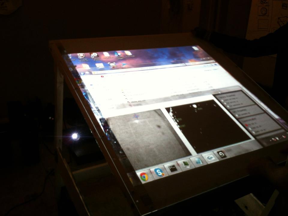
And here is the table itself.
For the BLOB recognition (these are the reflection-spots that the camera sees) I used the Community Core Vision, CCV system. This is a turnkey solution that relays recognition and transmits results using the TUIO protocol. TUIO is an open framework that defines a protocol and API for building multitouch interfaces. In principle, if there was more time, I would write my BLOB detector on OpenCV, since there is nothing particularly complicated for this task. The spots are clearly visible, and on OpenCV it would look like this - we get a picture, remove the noise, build a bitmap map, pass through the Canny algorithm, find the contours and then translate their coordinates into TUIO objects according to the specification. A calibration module would be needed to set the coordinates. CCV uses subtracting the background image from the resulting image, there is also an adaptive mode, which allows for slow background changes. On OpenCV, this can be implemented using the codebook and connected components method.
Now we have a system broadcasting TUIO objects, and we can use everything that accepts these objects, or write to the client ourselves. For example, in Java, this is done quite easily, there are many examples on the network.
CCV settings.
Further, since it was planned to use this table to control sound synthesis, the TUIO module for Ableton was used, which allows you to attach gestures to sound generation parameters, instruments, and so on. After that, Alexander Zhedelev was engaged in tuning the key, pairing with other recordings, and in general experimented as he wanted. At the end of the video, something like that is shown.
And here is an edited version. Look in the headphones.
As you can see in the video, we already played, put paper on the glass and painted on it. Got a playing drawing.
One observation. It is not necessary to touch the glass - Already at some distance from it, reflection occurs, and the camera captures it. There is space for the game with the settings, and as a result, you can make an air touch screen.
There is one inconvenience associated with the TUIO protocol, its objects must be relayed. I.e; if I want to run beautiful visuals and sound synthesis in parallel, then I need a repeater, because if the interface module accepts a TUIO object, then let's say Flash visuals no longer see this object.
I want to say thanks to all the people who participated, especially Alexander Zhedelev , Sergey Dragunov, Krista Koester.
AudioKinetica