Another PWM program or Attiny13a rehabilitation with Zen
I greet Habr, and all its many inhabitants!
I must make a reservation right away that what is being discussed here is not very designed for beginners, nevertheless, if there is interest and a craving for study, on the contrary, please know.
And this time, we will talk about the implementation of a hybrid PWM, which has already spawned many in the network. So I think one more, or two, or three (bonus), will not be superfluous or will not be superfluous.
So, first of all, why is it hybrid: first of all, because it is not 100% hardware, but also not 100% software.
What would it mean: a hardware counter is used for the implementation, but the output is generated not in one channel of the I / O port, but in three at once, with a configuration mask that masks the port channels in a timer interrupt.
What is the difference from hardware? Yes, everything is simple - among the channels for the Attiny13a microcontroller.
Now in more detail.
Who needs this and why? Well, the main field of application of such tasks is the control of motors - asynchronous, bipolar and unipolar - step-by-step, controllers of light and sound effects, ultrasonic devices (ultrasonic baths, engravers, mixers, etc.), etc. Of course, specialized controllers have been created for such purposes, but why look for, spend money, and dig LH, if you have a small pet at hand.
I focused on the first question when interest in him appeared suddenly, while reading one of the forums where one developer (let's call him “Saddened”) was saddened by the fact that the Attiny13a microcontroller, without having enough PWM hardware channels, could not boast necessary performance for software implementation of the conceived.
“Saddened” tried many options, changed constants, optimized C code, even enabled interrupts, but all in vain. And the topic he raised on the forum has gone bad, in some shaggy year, remaining unresolved and unrequited.
I was interested in how slow the PWM program mode for the mentioned microcontroller, which operates at 9.6 MHz. And I, having sketched a small source, using as much as possible all aspects described by “Sorrowed” and implementing them, slowly got on the three paws of Tinik the 13th PWM, at a frequency of ... about 4 kHz, with software emulation in Proteus.
Little ... Too Little! And somehow it’s all strange ... but insanely interesting, because if you do not defeat such a simple task, then it really is one of the first, little disappointments, and the direct road to more productive and sophisticated chips, which cost accordingly. On the other hand, it’s rather a plus, but still we will understand.
And then I thought: “And why, in fact, synchronization is built on timer overflows when the task is implemented through comparisons ?!”
And it's true, because in overflow mode the timer is simply obliged to cause an interrupt only once, when overflowing, after going through a full cycle. Slightly modifying the source received about 40 kHz. "Already better, but still - there is something wrong!"
In general, I will not bore you anymore: all the variables were declared in registers, the code was optimized for performance
and size (almost all disappeared), and with further games two more modes were obtained with relative pulse offsets.
And then new optimizations followed, as a result of which the slowest of the modes (6 phases) was rewritten to inline assembler. And this was done by accident, when I drew attention to the code obtained after compilation, which, to put it mildly simply, surprised me greatly! Even when declaring variables in registers, the compiler decided to do all the operations through time pairs, so the code was almost doubled, and this with size optimization turned on! A few extra movements and a gain of 40 bytes from the first option, and almost 10 kHz increase in frequency.
The result was three modes:
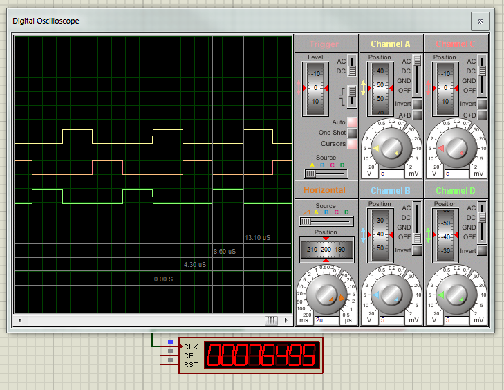
1. Pulses with a phase shift, the maximum available frequency is 75.500 kHz at CLK = 9.6 MHz (at CLK = 20 MHz, the frequency is close to 160 kHz), PWM duty cycle = 33.3%; period — three phases:
2. The pulses are shifted by a third, the maximum frequency is 37.400 kHz (75 kHz at CLK = 20 MHz), duty cycle = 50%, the period is six phases (without using assembler it was not possible to overcome the limit of 28 kHz, for more details see the source code):

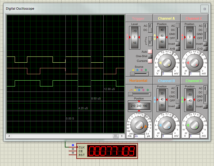
3. The pulses are shifted by half, the maximum frequency as in the first mode, duty cycle = 66.6%, the period is three phases:
The frequency here means the complete repetition of pulses along three channels before repeating in the period (or the period of one pulse). Yes, I must say that changing the duty cycle was not included in the scope of this task, although it is very simple to do this using the second timer comparison register (though this is true only for the first mode). In this case, the frequency change is implemented, and implemented through a change in the phase width (more in the source code).
Why so many modes? This is not all, and all of their many are due to the characteristics of certain devices.
So, for example, asynchronous motors are controlled by the first mode, and unipolar stepshops are controlled by the second mode (however, they also need fewer or more channels, but if there is an example, expanding or decreasing the number of channels is nothing).
To obtain a lower frequency programmatically, you must change the register of the timer divider.
If this is too much (for example for stepper motors), it is necessary to lower the frequency of the microcontroller.
So at a chip frequency of 128 kHz, with the CLK divider set, without a timer divider and a minimum pulse width (maximum frequency), when using the second mode, the pulse frequency is 62 Hz.
If we talk about controlling an asynchronous motor, then when using an engine with 12 fields, we get the maximum pulse repetition rate when using the first mode of about 20 kHz (~ 78/4), which is undoubtedly as much, due to the lack of motors that can rotate on such revolutions (per second). : o)
Of course, the calculations above do not reflect the overhead costs that full control requires, such as reading from Hall sensors or inverse EMF, adjusting the phase duration, etc. But with such a margin in frequencies, these tasks are solved easily, right in the main program cycle.
Separately, I apologize to the gurus, who are nervous about the conditions on one line, but here it was done deliberately for the convenience of quick commenting. The second, and more prosaic reason: I hate to endure - / * comments with asterisks * /, although when switching to inline - nothing else was given.
If you intend to use my code in your project when it begins to bloat and grow into your handlers, you must arm all declarations of the variables used in the registers with the keyword “volatile”, as a result of which the compiler will snap that he wanted to spit on your requests, and that in in case he pleases, then he will use these registers at his discretion (in case of shortage of such).
I tried to reflect the more detailed information in the comments as much as possible while trying to be as brief as possible when coding:

I will be happy to answer your questions and help with changing signal configurations, if of course it is required.
With all of the above, I want to indicate: I do not position myself as a super-optimizer, super-programmer and super-electronic engineer.
I wrote all that was said so that beginners would believe that there are no invincible tasks, and professionals paid attention to chips that are too early to write off, and in many classes of problems they can find worthy application.
PS: For beginners: IMHO, the project is not interesting enough for beginners, due to the use of high frequencies. However, the controller is flashed with firmware with an uncommented line in the main loop for changing the phase width, at a frequency of 4.8 MHz with the frequency divider (4.8 / 8) turned on (I just don’t remember until the code was optimized or after), and with the LEDs connected on the PB0, PB1 lines, PB2, looks funny in the role of a desktop flasher.
Although some, especially nervous individuals say that "this garbage is annoying to the brain of the elbows." :)
PPS: For NOT newcomers: in addition, I would like to talk about optimization, and the use (without the help of friends!) Of a similar code:
And the "wrong" use of the form:
The result will be the same, but the second example will be executed MUCH longer in time, and the code will BE significantly inflated.
And why?! And I will not say, you yourself guess! :)
On this note, I propose to stop and get acquainted with the attached materials: the
project for Proteus 8.1 and the source code created in Atmel Studio 6.2
Thank you for your attention, see you soon!
Use in commercial projects, resale of source code and use for profit is prohibited.
The source texts are distributed free of charge, if used on other sites
or in other sources, the author’s indication and notification of placement is mandatory.
I must make a reservation right away that what is being discussed here is not very designed for beginners, nevertheless, if there is interest and a craving for study, on the contrary, please know.
And this time, we will talk about the implementation of a hybrid PWM, which has already spawned many in the network. So I think one more, or two, or three (bonus), will not be superfluous or will not be superfluous.
So, first of all, why is it hybrid: first of all, because it is not 100% hardware, but also not 100% software.
What would it mean: a hardware counter is used for the implementation, but the output is generated not in one channel of the I / O port, but in three at once, with a configuration mask that masks the port channels in a timer interrupt.
What is the difference from hardware? Yes, everything is simple - among the channels for the Attiny13a microcontroller.
Now in more detail.
Who needs this and why? Well, the main field of application of such tasks is the control of motors - asynchronous, bipolar and unipolar - step-by-step, controllers of light and sound effects, ultrasonic devices (ultrasonic baths, engravers, mixers, etc.), etc. Of course, specialized controllers have been created for such purposes, but why look for, spend money, and dig LH, if you have a small pet at hand.
I focused on the first question when interest in him appeared suddenly, while reading one of the forums where one developer (let's call him “Saddened”) was saddened by the fact that the Attiny13a microcontroller, without having enough PWM hardware channels, could not boast necessary performance for software implementation of the conceived.
“Saddened” tried many options, changed constants, optimized C code, even enabled interrupts, but all in vain. And the topic he raised on the forum has gone bad, in some shaggy year, remaining unresolved and unrequited.
I was interested in how slow the PWM program mode for the mentioned microcontroller, which operates at 9.6 MHz. And I, having sketched a small source, using as much as possible all aspects described by “Sorrowed” and implementing them, slowly got on the three paws of Tinik the 13th PWM, at a frequency of ... about 4 kHz, with software emulation in Proteus.
Little ... Too Little! And somehow it’s all strange ... but insanely interesting, because if you do not defeat such a simple task, then it really is one of the first, little disappointments, and the direct road to more productive and sophisticated chips, which cost accordingly. On the other hand, it’s rather a plus, but still we will understand.
And then I thought: “And why, in fact, synchronization is built on timer overflows when the task is implemented through comparisons ?!”
And it's true, because in overflow mode the timer is simply obliged to cause an interrupt only once, when overflowing, after going through a full cycle. Slightly modifying the source received about 40 kHz. "Already better, but still - there is something wrong!"
In general, I will not bore you anymore: all the variables were declared in registers, the code was optimized for performance
and size (almost all disappeared), and with further games two more modes were obtained with relative pulse offsets.
And then new optimizations followed, as a result of which the slowest of the modes (6 phases) was rewritten to inline assembler. And this was done by accident, when I drew attention to the code obtained after compilation, which, to put it mildly simply, surprised me greatly! Even when declaring variables in registers, the compiler decided to do all the operations through time pairs, so the code was almost doubled, and this with size optimization turned on! A few extra movements and a gain of 40 bytes from the first option, and almost 10 kHz increase in frequency.
The result was three modes:
1. Pulses with a phase shift, the maximum available frequency is 75.500 kHz at CLK = 9.6 MHz (at CLK = 20 MHz, the frequency is close to 160 kHz), PWM duty cycle = 33.3%; period — three phases:
2. The pulses are shifted by a third, the maximum frequency is 37.400 kHz (75 kHz at CLK = 20 MHz), duty cycle = 50%, the period is six phases (without using assembler it was not possible to overcome the limit of 28 kHz, for more details see the source code):
3. The pulses are shifted by half, the maximum frequency as in the first mode, duty cycle = 66.6%, the period is three phases:
The frequency here means the complete repetition of pulses along three channels before repeating in the period (or the period of one pulse). Yes, I must say that changing the duty cycle was not included in the scope of this task, although it is very simple to do this using the second timer comparison register (though this is true only for the first mode). In this case, the frequency change is implemented, and implemented through a change in the phase width (more in the source code).
Why so many modes? This is not all, and all of their many are due to the characteristics of certain devices.
So, for example, asynchronous motors are controlled by the first mode, and unipolar stepshops are controlled by the second mode (however, they also need fewer or more channels, but if there is an example, expanding or decreasing the number of channels is nothing).
To obtain a lower frequency programmatically, you must change the register of the timer divider.
If this is too much (for example for stepper motors), it is necessary to lower the frequency of the microcontroller.
So at a chip frequency of 128 kHz, with the CLK divider set, without a timer divider and a minimum pulse width (maximum frequency), when using the second mode, the pulse frequency is 62 Hz.
If we talk about controlling an asynchronous motor, then when using an engine with 12 fields, we get the maximum pulse repetition rate when using the first mode of about 20 kHz (~ 78/4), which is undoubtedly as much, due to the lack of motors that can rotate on such revolutions (per second). : o)
Of course, the calculations above do not reflect the overhead costs that full control requires, such as reading from Hall sensors or inverse EMF, adjusting the phase duration, etc. But with such a margin in frequencies, these tasks are solved easily, right in the main program cycle.
Separately, I apologize to the gurus, who are nervous about the conditions on one line, but here it was done deliberately for the convenience of quick commenting. The second, and more prosaic reason: I hate to endure - / * comments with asterisks * /, although when switching to inline - nothing else was given.
If you intend to use my code in your project when it begins to bloat and grow into your handlers, you must arm all declarations of the variables used in the registers with the keyword “volatile”, as a result of which the compiler will snap that he wanted to spit on your requests, and that in in case he pleases, then he will use these registers at his discretion (in case of shortage of such).
I tried to reflect the more detailed information in the comments as much as possible while trying to be as brief as possible when coding:
I will be happy to answer your questions and help with changing signal configurations, if of course it is required.
With all of the above, I want to indicate: I do not position myself as a super-optimizer, super-programmer and super-electronic engineer.
I wrote all that was said so that beginners would believe that there are no invincible tasks, and professionals paid attention to chips that are too early to write off, and in many classes of problems they can find worthy application.
PS: For beginners: IMHO, the project is not interesting enough for beginners, due to the use of high frequencies. However, the controller is flashed with firmware with an uncommented line in the main loop for changing the phase width, at a frequency of 4.8 MHz with the frequency divider (4.8 / 8) turned on (I just don’t remember until the code was optimized or after), and with the LEDs connected on the PB0, PB1 lines, PB2, looks funny in the role of a desktop flasher.
Although some, especially nervous individuals say that "this garbage is annoying to the brain of the elbows." :)
PPS: For NOT newcomers: in addition, I would like to talk about optimization, and the use (without the help of friends!) Of a similar code:
 byte	A=0,	B=1,	C=2;
 if (A==0 || B==1 || C==2) doSomething(); / if (A==0 && B==1 && C==2) doSomething();
And the "wrong" use of the form:
if (A==0 | B==1 | C==2) doSomething(); / if (A==0 & B==1 & C==2) doSomething();
The result will be the same, but the second example will be executed MUCH longer in time, and the code will BE significantly inflated.
And why?! And I will not say, you yourself guess! :)
On this note, I propose to stop and get acquainted with the attached materials: the
project for Proteus 8.1 and the source code created in Atmel Studio 6.2
Thank you for your attention, see you soon!
Use in commercial projects, resale of source code and use for profit is prohibited.
The source texts are distributed free of charge, if used on other sites
or in other sources, the author’s indication and notification of placement is mandatory.