Odroid-W + W Docking Board LCD
Hello! Perhaps my article will look a little "nubovaty", but I personally could not find a similar HOW TO on the Russian-speaking Internet. It will be about the initial deployment of the operating system on a single-board Odroid-W computer from Hardkernel, which has already been written on Habré for two articles of a descriptive nature. The peculiarity will be the use together with the “ W Docking Board with TFT LCD ” board itself , without which, since the capabilities of this piece of iron are not fully disclosed.
What I would like to talk about:
1) Preparation and installation of the operating system;
2) Graphics output to an external display;
3) Displaying graphics on the “W Docking Board” display;
4) Connecting a webcam;
5) Wi-Fi dongle connection.
What I plan to talk about next time if this article does not fly into a black hole:
6) Connecting a 4G modem with subsequent distribution of the Internet via Wi-Fi.
On Odroid we will put the anti-malignant Debian . All the preparatory work is done on a PC with Windows 7 installed. The preparatory work in nix-based OSes is made much simpler and does not require additional software.
So, let's begin. First you need to get a micro-sd card> 4 Gb in size, as well as a card reader for this (+ adapter). Here the main rule - the more the better. Well, of course, the higher the class of the card, the faster everything will work. First you need to download the Raspbian distribution of the latest version of the assembly, as well as utilities SDFormatter , Win32DiskImager , SSH client (for example Putty ).
First, insert the SD card into the card reader and launch SDFormatter, select the drive letter of our card, the QUICK FORMAT option, and click Format. Running fast enough.
Next, run Disk Imager, select the downloaded distribution image and write to the card. Not very fast.
Next, insert the memory card into Odroid-W, connect the W Docking Board network cable to the microcomputer. Then, after waiting a bit, you need to determine the ip-address of the board (I connected to my router, and I saw the corresponding DHCP address in the router’s web interface). Then you need to connect with the SSH client (I use the proprietary SecureCRT) Putty is the easiest and easiest way. I will not dwell on setting up SSH there, firstly, everything is simple, and secondly, there are enough articles on the Internet. To connect, you must use the pi username and raspberry password. Immediately I recommend that you run sudo su and passwd and set your password for the root user and then log in from there (although there may be many opponents of this method who use sudo).
To connect an external display, you also need: a monitor / TV with an HDMI connector, an HDMI-microHDMI cable, or other options, such as DVI-microHDMI and other perversions, depending on the capabilities. After connecting the monitor, most likely nothing will be displayed on the screen, but this is solved quite simply, you need to change the /boot/config.txt file using the nano editor, or immediately install mc, in the future it will come in handy anyway. You need to uncomment the line hdmi_safe = 1
A small part of the setup, such as starting X, can be learned from the third part. I did not pay much attention to the output of the image to the monitor, because It was supposed to be a portable solution using an integrated screen.
I did not invent this text myself, but found it in the official English language wiki. Therefore, I provide a link to the original, further translation and some comments. In fact, even this instruction was not so easy to find (at least for me).
Edit the file /etc/modprobe.d/raspi-blacklist.conf, you need to comment:
Add to the file / etc / modules
In fact, I used rotate = 270, I found it more convenient.
In the off manual it is written how to make an autologin, but I don’t really like this idea.
I quote it as it is, in the / etc / inittab file,
add the line:
Where pi is the name of the user.
And startup Xs. To be honest, given the size of the screen, I would not recommend using them, but I’ll give for those who want to make a glamorous watch from Odroid-W
Add to /etc/rc.local
where pi is the name of the user.
A.J. disable the option in /usr/share/X11/xorg.conf.d/99-fbturbo.conf
Which displays the picture on an external screen (via HDMI).
And the final touch, in /boot/cmdline.txt we add at the end of the line:
And after the reboot, you will see a friendly blinking GUY LXDE.
Warning! Hereinafter, links to additional equipment will be provided, but: a) are not advertising, b) do not contain referrals, c) it is not recommended for purchase.
I used the simplest Chinese noname webcam , which was subjected to some mechanical modifications upon receipt. To work with it, it was necessary to install the following packages: libv4l and fswebcam for installing and determining capabilities and mjpg-streamer for streaming images from the camera.
The first 2 packages are in the repository, install them aptitude install libv4l-0 fswebcam
And download mjpg-streamer from SF and unpack it into * a folder convenient for you * (for me it's just in / root).
When connecting the camera to lsusb, something related to the camera should appear (especially when using branded devices):
And in dmesg:
Next, run fswebcam:
And we determine that (in this case mine) the camera works in YUYV mode and supports 2 resolutions:
Next, you need to prepare the mjpg-streamer startup script. A large set of examples with a description is in fact in ./mjpg-streamer/start.sh
You can, in principle, not use this file, but run directly from the console. My option is this:
Where the device is indicated, resolution, number of frames per second, camera mode, jpeg quality and output file (built-in web server).
You can go to the browser at http: // [odroid.w.ip.address]: 8080 and watch the stream from your camera. Done!
Odroid-W has a mipi-csi interface for connecting the matrix directly to SoC, but working with these cameras remains behind the scenes (their cost is not very good).
I bought Wi-Fi dongle on the well-known Chinese e-market for quite ridiculous money, the main thing here is not to pierce, and not to buy a dong that does not know how to support AP.
Oops! While I am writing this article, my handkerchiefsympathetic strongly zachudila, and refused to be included. But to finish what I started, I’ll just provide links to 2 manuals that can be used to configure Wi-Fi dongles on this board:
http://hizz.livejournal.com/3817.html
https://blog-agents.rhcloud.com/ wifi-pi-point /
Initially, I really wanted to tame my portable CBR KB 477W keyboard to this board , but this could not be done. This is due to the clumsy bluez utility in Linux. In fact, I spent a lot of time to get this bunch to work, almost a half-kick started my Chinese bt-dongle, and even it came to authorizing the keyboard in the system, but it didn’t go further. I freaked out and bought the A4Tech GK-85 wireless keyboard , which works flawlessly (but at least why not work there?).
Unwritten part 6. In the near future I want to finish the work of a 4G modem in the system (I have already tested the performance in large Debian, plus I played with the whistle firmware on a virtual network card ( Huawei E3272)). After finishing work, you should get a portable Internet access point for external devices with the ability to broadcast a signal from the camera.
not happy owners will have to trample their own path in the world of miniature computers. Good luck everyone!
In the distant plans (and the initial ones, up to the idea with a portable Internet point), attach this bundle to my project of a radio-controlled car on Arduino. Odroid needs to take on FPV and alternative control with a smartphone. True, this project is moving rather slowly, but I hope that it will turn out to be completed and published on this resource.
UPD 17/11/14 Added a couple of photos. No photographer from me. And from the iPhone there is no camera. If anyone shows interest in the project, then at the weekend I will try to make more sensible pictures in daylight and on the photomill.
Thanks to everyone who read.
My raspberry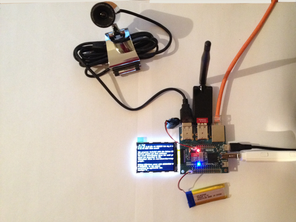
What I would like to talk about:
1) Preparation and installation of the operating system;
2) Graphics output to an external display;
3) Displaying graphics on the “W Docking Board” display;
4) Connecting a webcam;
5) Wi-Fi dongle connection.
What I plan to talk about next time if this article does not fly into a black hole:
6) Connecting a 4G modem with subsequent distribution of the Internet via Wi-Fi.
On Odroid we will put the anti-malignant Debian . All the preparatory work is done on a PC with Windows 7 installed. The preparatory work in nix-based OSes is made much simpler and does not require additional software.
Part one
So, let's begin. First you need to get a micro-sd card> 4 Gb in size, as well as a card reader for this (+ adapter). Here the main rule - the more the better. Well, of course, the higher the class of the card, the faster everything will work. First you need to download the Raspbian distribution of the latest version of the assembly, as well as utilities SDFormatter , Win32DiskImager , SSH client (for example Putty ).
First, insert the SD card into the card reader and launch SDFormatter, select the drive letter of our card, the QUICK FORMAT option, and click Format. Running fast enough.
Next, run Disk Imager, select the downloaded distribution image and write to the card. Not very fast.
Next, insert the memory card into Odroid-W, connect the W Docking Board network cable to the microcomputer. Then, after waiting a bit, you need to determine the ip-address of the board (I connected to my router, and I saw the corresponding DHCP address in the router’s web interface). Then you need to connect with the SSH client (I use the proprietary SecureCRT) Putty is the easiest and easiest way. I will not dwell on setting up SSH there, firstly, everything is simple, and secondly, there are enough articles on the Internet. To connect, you must use the pi username and raspberry password. Immediately I recommend that you run sudo su and passwd and set your password for the root user and then log in from there (although there may be many opponents of this method who use sudo).
Part two
To connect an external display, you also need: a monitor / TV with an HDMI connector, an HDMI-microHDMI cable, or other options, such as DVI-microHDMI and other perversions, depending on the capabilities. After connecting the monitor, most likely nothing will be displayed on the screen, but this is solved quite simply, you need to change the /boot/config.txt file using the nano editor, or immediately install mc, in the future it will come in handy anyway. You need to uncomment the line hdmi_safe = 1
A small part of the setup, such as starting X, can be learned from the third part. I did not pay much attention to the output of the image to the monitor, because It was supposed to be a portable solution using an integrated screen.
Part three
I did not invent this text myself, but found it in the official English language wiki. Therefore, I provide a link to the original, further translation and some comments. In fact, even this instruction was not so easy to find (at least for me).
Edit the file /etc/modprobe.d/raspi-blacklist.conf, you need to comment:
#blacklist spi-bcm2708
Add to the file / etc / modules
fbtft_device name=adafruit22a verbose=0 rotate=90
In fact, I used rotate = 270, I found it more convenient.
In the off manual it is written how to make an autologin, but I don’t really like this idea.
I quote it as it is, in the / etc / inittab file,
add the line:
#1:2345:respawn:/sbin/getty --noclear 38400 tty1
1:2345:respawn:/bin/login -f pi tty1 /dev/tty1 2>&1
Where pi is the name of the user.
And startup Xs. To be honest, given the size of the screen, I would not recommend using them, but I’ll give for those who want to make a glamorous watch from Odroid-W
Add to /etc/rc.local
su -l pi -c "env FRAMEBUFFER=/dev/fb1 startx &"
where pi is the name of the user.
A.J. disable the option in /usr/share/X11/xorg.conf.d/99-fbturbo.conf
# Option "fbdev" "/dev/fb0"
Which displays the picture on an external screen (via HDMI).
And the final touch, in /boot/cmdline.txt we add at the end of the line:
fbcon=map:10
And after the reboot, you will see a friendly blinking GUY LXDE.
Part four
Warning! Hereinafter, links to additional equipment will be provided, but: a) are not advertising, b) do not contain referrals, c) it is not recommended for purchase.
I used the simplest Chinese noname webcam , which was subjected to some mechanical modifications upon receipt. To work with it, it was necessary to install the following packages: libv4l and fswebcam for installing and determining capabilities and mjpg-streamer for streaming images from the camera.
The first 2 packages are in the repository, install them aptitude install libv4l-0 fswebcam
And download mjpg-streamer from SF and unpack it into * a folder convenient for you * (for me it's just in / root).
When connecting the camera to lsusb, something related to the camera should appear (especially when using branded devices):
pi:~# lsusb
Bus 001 Device 007: ID 1871:0101 Aveo Technology Corp.
And in dmesg:
pi:~# dmesg
[ 1182.284021] usb 1-1.4: new high-speed USB device number 8 using dwc_otg
[ 1182.394987] usb 1-1.4: New USB device found, idVendor=1871, idProduct=0101
[ 1182.395067] usb 1-1.4: New USB device strings: Mfr=1, Product=2, SerialNumber=0
[ 1182.395087] usb 1-1.4: Product: USB2.0 Camera
[ 1182.395135] usb 1-1.4: Manufacturer: AVEO Technology Corp.
[ 1182.403956] uvcvideo: Found UVC 1.00 device USB2.0 Camera (1871:0101)
[ 1182.408696] input: USB2.0 Camera as /devices/platform/bcm2708_usb/usb1/1-1/1-1.4/1-1.4:1.0/input/input4
Next, run fswebcam:
pi:~# fswebcam --verbose
And we determine that (in this case mine) the camera works in YUYV mode and supports 2 resolutions:
Using palette YUYV
Adjusting resolution from 384x288 to 352x288.
Next, you need to prepare the mjpg-streamer startup script. A large set of examples with a description is in fact in ./mjpg-streamer/start.sh
You can, in principle, not use this file, but run directly from the console. My option is this:
pi:~# ./mjpg_streamer -i "input_uvc.so -d /dev/video0 -r 384x288 -f 10 -y -q 100" -o "./output_http.so -w ./www"
MJPG Streamer Version: svn rev: 3:172M
 i: Using V4L2 device.: /dev/video0
 i: Desired Resolution: 384 x 288
 i: Frames Per Second.: 10
 i: Format............: YUV
 i: JPEG Quality......: 100
Where the device is indicated, resolution, number of frames per second, camera mode, jpeg quality and output file (built-in web server).
You can go to the browser at http: // [odroid.w.ip.address]: 8080 and watch the stream from your camera. Done!
Odroid-W has a mipi-csi interface for connecting the matrix directly to SoC, but working with these cameras remains behind the scenes (their cost is not very good).
Part five
I bought Wi-Fi dongle on the well-known Chinese e-market for quite ridiculous money, the main thing here is not to pierce, and not to buy a dong that does not know how to support AP.
Oops! While I am writing this article, my handkerchief
http://hizz.livejournal.com/3817.html
https://blog-agents.rhcloud.com/ wifi-pi-point /
Part 9¾
Initially, I really wanted to tame my portable CBR KB 477W keyboard to this board , but this could not be done. This is due to the clumsy bluez utility in Linux. In fact, I spent a lot of time to get this bunch to work, almost a half-kick started my Chinese bt-dongle, and even it came to authorizing the keyboard in the system, but it didn’t go further. I freaked out and bought the A4Tech GK-85 wireless keyboard , which works flawlessly (but at least why not work there?).
Unwritten part 6. In the near future I want to finish the work of a 4G modem in the system (I have already tested the performance in large Debian, plus I played with the whistle firmware on a virtual network card ( Huawei E3272)). After finishing work, you should get a portable Internet access point for external devices with the ability to broadcast a signal from the camera.
In conclusion
It is unfortunate that Hardkernel were forced to curtail the production of this microcomputer, because The project turned out to be quite interesting. In view of this wang, that the number of manuals devoted to this board will remain extremely low, it makes me very sad and sad. AndPS
In the distant plans (and the initial ones, up to the idea with a portable Internet point), attach this bundle to my project of a radio-controlled car on Arduino. Odroid needs to take on FPV and alternative control with a smartphone. True, this project is moving rather slowly, but I hope that it will turn out to be completed and published on this resource.
My BMW
UPD 17/11/14 Added a couple of photos. No photographer from me. And from the iPhone there is no camera. If anyone shows interest in the project, then at the weekend I will try to make more sensible pictures in daylight and on the photomill.
Thanks to everyone who read.