Hexapod ROS Robot

The hexapod robot is a platform that uses six legs to move. After watching a lot of videos on the Internet, it became clear that it was very interesting to watch the movement of such robots. And then there was a desire to do something similar, but with a BeagleBone Black (hereinafter BBB) single-board computer on board, because there were no such projects yet. Information about such robots was not easy to find, especially with regard to the software component. For some time it was not clear where to start, but it was soon decided to start with the manufacture of the robot construct - the chassis and the electronic component, and then start programming what happened.
Having studied at Robocraft.ru some articles about the operating system for robots - ROS - it was decided to build control on it, especially since BBB should have had enough power for this. In addition, ROS is a very promising area in robotics with many tools and turnkey solutions for development.
The choice of hardware
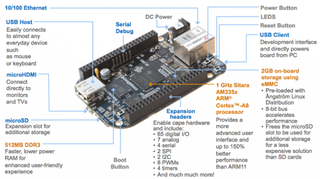
As noted above, BeagleBone Black has become the brain of the system: BBB also supports Ubuntu, but with a core for ARM architecture. The experimental mode, in which ROS for ARM is still running, had no effect on the work process, since tools that were stable on linux-arm were used. The next important part is the servo controller. BBB has several PWM channels, but they are clearly not enough for 18 servos. In addition, PWM control will unnecessarily load the processor. It is more logical to use a ready-made servo controller with control via some interface. The choice fell on the suitable Mini Maestro 18-Channel USB Servo Controller:
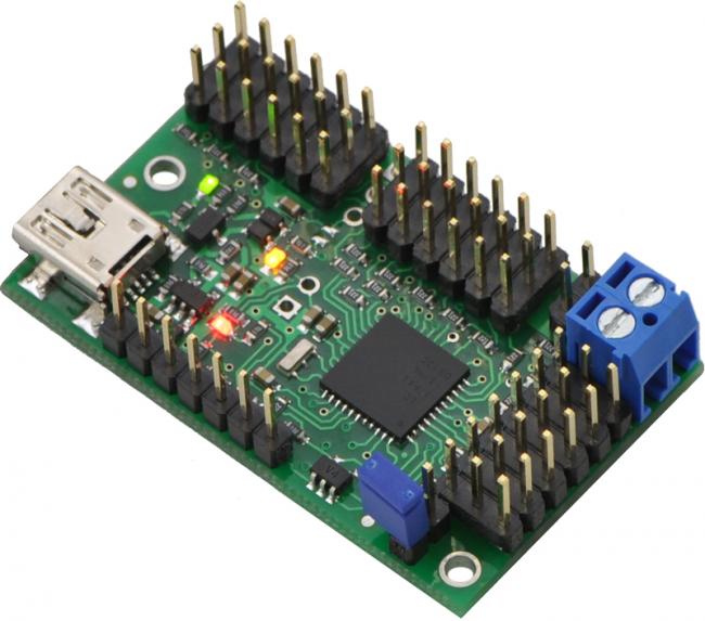
This controller has 18 channels for servo, has a UART and USB interface. It is controlled through its own protocol, which includes settings of the target angle of the servo drive, as well as its speed and acceleration; in addition, it has convenient calibration tools in the graphical shell.
But it’s not possible to quickly connect Mini Maestro to BBB, since their UART interface levels are different: 5 V and 3.3 V. The output was the use of an additional device - a logic level converter, which converts 3.3 V to 5 V and vice versa. Such a thing came from Sparkfaun.com. This is BOB-08745 :

Now you can easily connect the BBB and the controller so that they communicate via UART.
For future research, I wanted IMU so that the robot could somehow feel in space. An IMU with an accelerometer, magnetometer and gyroscope is also ordered by Pololu:
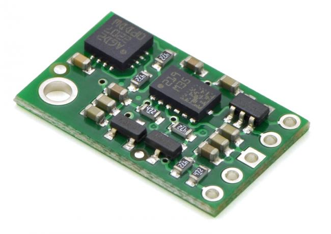
This is a small MinIMU-9 v2 board with two L3GD20 and LSM303DLHC chips, which communicate with peripherals via the I2C interface. MiniIMU is capable of operating from 2.5V to 5.5V, so no converters were needed.
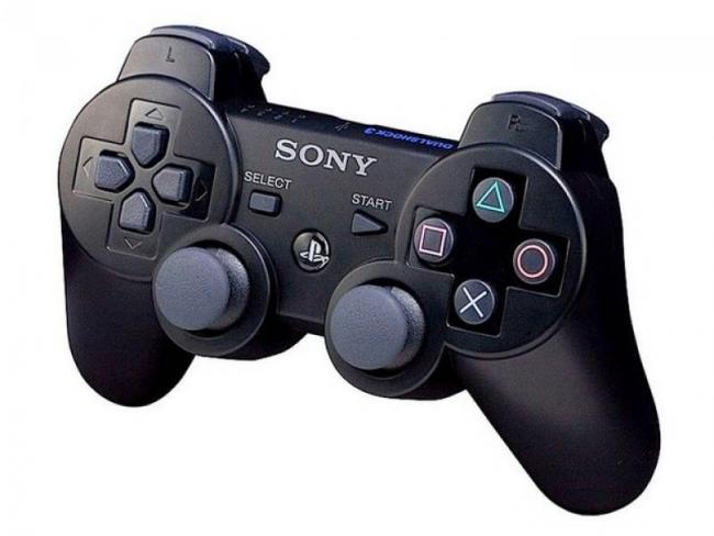
On many videos, hexapods were controlled by a gamepad from various consoles. And not in vain. With many buttons and two “analog” knobs, the joystick becomes a convenient control device. A driver for the standard joystick was found in ROS, and in order to avoid connection problems, it was decided to purchase the original PS3 Dual Shock 3:
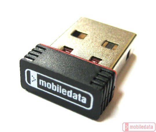
To connect via Bluetooth, obviously, a USB adapter was needed. As a result, I had two of them, because one of them did not want to work with the existing driver (more on this later). And MobileData UBT-206 - earned.
To connect the BBB with the desktop computer, the SSH protocol is used, which in turn uses, for example, Ethernet, Ethernet-over-USB (a technology that allows you to emulate an ethernet network via USB) or Wi-Fi. Connecting the wires every time is not very convenient and an additional USB Wi-Fi adapter was added to get rid of this. Having examined which adapter is best suited for BBB, it became clear that the arm-linux kernel supports the rtl8192cu driver on the basis of which a wide range of devices works. The compact NetGear WNA1000M was selected (in the picture along with MobileData UBT-206):

Although many recommend using adapters with an external antenna, this one works quite stably.
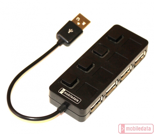
Well, to expand just one USB Host BBB connector, you need a USB hub. I liked this one - MobileData HDH-700, because it has buttons-switches for each of the four devices:
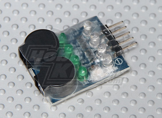
The next item is the batteries for all on-board devices. Battery - Li-Po 2200mAh, consisting of two cans. Together with it, two voltage regulators convert the battery voltage to the required 5V (for BBB and servo controller) and 6V (for servo drives). There is also a low-charge indicator on the battery, which pierces when the battery voltage drops to a minimum.
Choice of design and servos
There are many designs of hexapods made from various materials. I will not upload photos here, as they are easy to find on the Internet. The classic version consists of three drives on each leg, which gives a sufficient degree of freedom. Of course, you can get by with two drives - but the movements will become more "twitchy."
Various materials and manufacturing techniques for suspension parts. It can be printing on a 3D printer or laser cutting from sheets of plastic, plywood or metal. Since there was no 3d printer at hand and the strength of the printed parts was poor, a design of metal was chosen, namely aluminum and duralumin. Moreover, at work I had access to a CNC milling machine, so it was decided to make parts of metal sheets by milling.
The main example, in the image of which its own design was created, is Lynxmotion Phoenix :

A model with GrabCAD was also very helpful in creating it .
One of the main parts of the robot are servos. They must have sufficient torques and, for reliability, the gearbox should be selected from metal. Such servos from renowned firms Hitec and Futaba cost about $ 20- $ 30. Therefore, instead of the "not cheap" Hitec HS-645 / 485MG servos, Chinese were ordered, which are half the price of the Turnigy TGY-S901D :
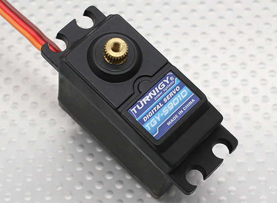
When powered at 6V, they are able to cope with a maximum load of 12.5 kg / cm, which was enough for a robot with an estimated weight of 2 kg. A stock in the Chinese servers is needed, as their quality leaves much to be desired. Some of them work with extraneous sounds from the very beginning. They also have a fairly large backlash and curved axis. But for $ 10 apiece - that's acceptable.
An aluminum disk fastener on the shaft was purchased for the servers to increase the strength and elasticity of the structure:

Creating 3d models in SolidWorks and manufacturing parts
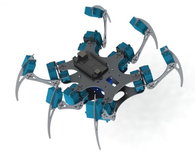
Thus, having decided on the basic set of components, I began to create a 3d drawing using SolidWorks. Here is a render of what happened (I didn’t draw all the cogs):
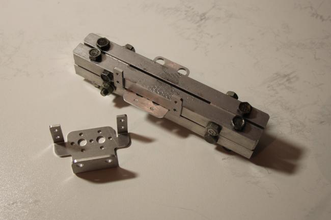
Separately, probably it’s worth stopping at some details and nodes. In addition to flat parts, parts obtained by bending were particularly difficult:

The development of these parts was obtained using a special tool in SolidWorks. They are cut from a sheet of aluminum 2 mm, removed from the body of an unnecessary device. It was attended by bending, so the aluminum brand was apparently suitable for this. The problem of bending all parts equally and evenly was solved with the help of a special tool, a vise and a hammer. It turned out even better than I expected from a manual manufacturing method.
The next item is the bushings on the side of the servo opposite the shaft. Through these bushings, servos are mounted at the bottom of the frame.
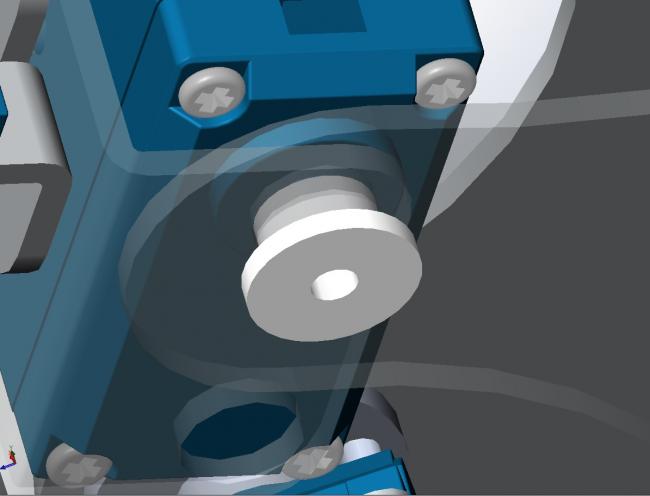
The bushings are necessary to evenly distribute the load on the two plates of the frame, otherwise the servo shaft may bend. The bushings are all made on the same milling machine from caprolon - a polymer used in anti-friction parts.

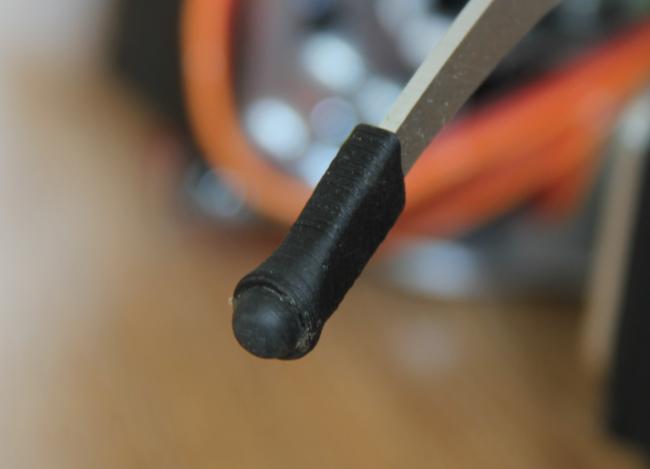
And the last thing to stop at is the details on the ends of the legs.
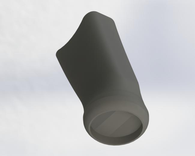
They are printed on a 3D printer made of ABS plastic. Further, rubber legs for instrument housings are glued into their round grooves. The result is a complete part that contributes to an increase in the friction of contact with the surface. Without them, the ratio of the inertia of the robot and the “tenacity” of the legs leads to slippage of the latter when walking and other actions on any flat surface.
The remaining flat parts are made of duralumin 2.2 mm thick.

Robot assembly
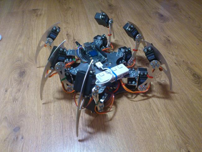
The assembly took place in several stages. This is due to debugging of its individual parts. At first, only the chassis with a servo controller was assembled, and control was carried out from the amd64 desktop computer via USB. Then came the BBB with the hub, and last but not least - the battery with stabilizers and IMU.
In the photo - various stages of assembly and the final result.


Beagle bone
On BBB, the Ubuntu 13.04 system from the finished image is installed . Today, this version of the distribution is no longer available for download, but there is only the latest and LTS. Kernel version 3.8.
eMMC was flashed through a microSD card. The easiest way to write an image to a USB flash drive is with Image Writer for Windows. Firmware instructions can be found here .
Now about initializing UART to BBB. This is done through the Device Tree Compiler (DTC) and more details can be found here . You can install it on the BBB this way: Taken from here .
wget -c https://raw.github.com/RobertCNelson/tools/master/pkgs/dtc.sh

chmod +x dtc.sh

./dtc.sh
After Rx and Tx UART appeared on pins P9_11 and P9_13 (in the case of uart5), you can transfer data. And in order to change the bitrate, the stty utility is used. It is launched through a script, before starting work with the servo controller:
stty -F /dev/ttyO4 cs8 115200On the controller, the speed is set through the Maestro Control Center .
In order for the UART to “start up” each time the system starts, it’s worth adding a line
sudo bash -c "echo enable-uart5 > /sys/devices/bone_capemgr.*/slots"to rc.local.
As described above, the IMU uses the I2C interface. I2C on BBB works by default, no additional steps are required to start it. But before writing the ROS node for IMU, it was useful to verify that the interface is connected correctly using the i2c-tools utility for Linux. Deal with I2C still helped the video .
The big problem was getting the joystick to work properly via bluetooth. Connecting it was not difficult - everything is in accordance with the description of the ps3joy node and the tutorial to it. Only the driver for the joystick, starting with kernel version 3.5, began to receive events from the device with a low frequency: about 5Hz. This is not enough for normal management. The problem is just mentioned here . Therefore, having tried a bunch of other drivers, I found one working for arm-linux. This is the sixad driver. But for him to make money on the BBB, he must be assembled manually. This was done for the Raspberry PI and is described in detail here . When compiling, for some reason I got an error:
error: ... was not declared in this scopeIt was resolved by adding the unistd.h header to each driver source file.
After the driver was assembled and installed, the gamepad still did not connect immediately. This was decided by changing the bluetooth configuration:
echo "DisablePlugins = input" >> /etc/bluetooth/main.confAfter that, it was possible to start the driver as a daemon and freely connect the joystick by pressing the PS3 button.
USB Wi-Fi works out of the box. For the client to connect to the router, you need to change the fields in / etc / network / interfaces:
wpa-ssid ""

wpa-psk ""
Ros
For starters, ROS was installed on a desktop computer. The Hydro Desktop-Full distribution version installed seamlessly on Ubuntu 13.04. On a "large" computer, it is convenient to debug written nodes and a kinematic model in ROS visualization tools. In addition, compilation is much faster than on BBB. Therefore, everything was developed on a computer, and then only transferred to the BBB and compiled there. Unfortunately, cross-compiling for ROS is still a difficult task.
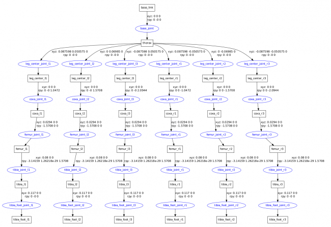
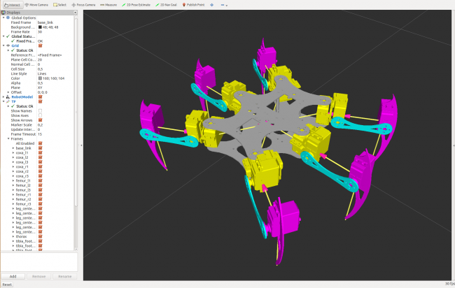
There is a convenient tool for visualization - rviz . It was used to view the resulting model and how it behaves under control. To do this, there is joint_state_publisher - a package containing tools for adjusting and repositioning the "joints" and robot_state_publisher- a package broadcasting the position of the robot in tf . The model itself is contained in the URDF file. It describes all segments (links) and their joints (joints), as well as their relative position. For clarity, 3d models of parts are attached in the STL format. But since the robot contains repeating parts (legs), it is convenient to use the XACRO (XML Macros) format, which is then converted to URDF. The main advantages of XACRO are the presence of macros, mathematical operations, and constants. In this way, code describing the robot model can be minimized. The figure shows the structure and visualization of the model in rviz.
When writing core nodes in C ++, the Eclipse Kepler IDE was used. You can read about the Eclipse configuration here.. In general, before starting, you should familiarize yourself with the tutorial , roscpp and catkin .
Software development
This article will not describe the code of the nodes; only their general structure and purpose will be presented. Read more about writing code in the next article.
So, the general diagram of the structure of ROS nodes on the BBB (in ellipses is the name of nodes, in rectangles is the name of topics):
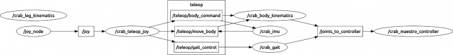
joy_node is a ready-made package that allows you to convert data from a file of a standard Linux device (/ dev / input / js) to “ Joy ” messages and Broadcast them to ROS topics. It will be useful to look in the tutorial package. Almost always, they contain many answers to questions.
crab_teleop_joy- a node that processes data from the joystick and converts them into messages for controlling the hexapod. For example, from the position along the two axes of the “analog” pen, the course angle is calculated, and its distance from the center affects the stride length. These values are then used in the gait generator. The logic of using certain combinations and sequences of button presses is also built. Received messages are transmitted further in three topics.
crab_leg_kinematics- service node. Its purpose is to solve the problem of inverse kinematics, that is, based on the coordinates of the end-effector (in my case, these are the tips of the legs) to calculate the angles of the joints (angles of servos). The service request is formed in the form of six vectors of the target position of the tips of the legs, and the answer comes in the form of 18 'servo angles. A site was written using the Kinematics and Dynamics Library ( KDL ), which is integrated into ROS. The node's clients are crab_body_kinematics and crab_gait.
crab_body_kinematics- calculates the vectors of the position of the ends of the legs based on the model of the robot URDF and data from the message, which contains the desired linear and angular deviations of the frame from the initial position, as well as the radius of the legs. Also, lifting commands from the starting position (when the robot lies on the frame and the legs are folded) and returning to the starting position are implemented.
crab_gait - a node that generates position vectors of the ends of the legs for the implementation of two types of gait. At the input there are messages containing commands about the type and state of the gait (to walk / stand) and the control values: heading and yaw angles and step size. The types of gait are tripod and ripple: A
gait of a tripod type is faster, but the load on the central legs is greater than on the front and rear legs, which affects the lifespan of servs.
The control is carried out using two "analog" joystick handles: the left - course change with constant yaw (moving "crab"), the right - course change with yaw change (moving back and forth and left and right).
crab_imu - MinIMU-9 driver, assembled from parts of the Arduino sketch . It contains an algorithm for calculating Euler angles based on data from MEMS sensors. It also contains a simple P-controller that generates effects that compensate for pitch and roll deviations. These actions are passed through the topic move_body to crab_body_kinematics to set the desired position of the legs.
crab_maestro_controller is the last driver node for Mini Maestro. At the input, he has 18 angular positions of the servos, which he converts into the communication protocol of the servo controller via UART.
The block diagram of the visualization is slightly different from the scheme of the robot system. In the visualization, all the same nodes except the crab_maestro_controller node, which are replaced by the crab_joint_publisher, joint_state_publisher, robot_state_publisher and tf nodes.

About the latter was written above.
crab_joint_publisher - converts messages intended for the controller into “ JointState ” messages , which are fed to the input of joint_state_publisher.
Now about some stages of development with video.
At first, all hexapods were controlled from a computer. The beginning was the test of inverse kinematics by drawing a circle of one of the legs:
Then the parts for controlling the position and orientation of the body are assembled:
And the embodiment of this on a real robot:
After that, I launched all this on the BBB and tested the IMU node:
Then the robot went ripple gait, controlled with a joystick:
And at the end of the hexapod capability today:
Conclusion
Creating a hexapod was a very interesting process, and the ROS capabilities and BeagleBone Black performance allow you to add and improve the software component of the robot. In this article, I wanted to show first of all the possibilities of convenient development using ROS, as well as pay attention to what tools were used to create the robot, without going into details. At the initial stage, it was most difficult to figure out where to start and what means to use. I hope this article will help you navigate the choice of development path.
PS Sources of the project on github