Remote controller for PC server with text console, without soldering iron and Arduino
annotation
Although one of the heroes of the second plan is the infrared port on the motherboard, I will not talk about remotes from TVs and their switching tracks in my favorite media player. In continuation of the story about the FreeNAS server , built from old iron, I will tell you how to equip it with an equally simple on-board controller with a serial port (console) over IP (Serial-over-LAN), remote reset (RESET) and controlled power supply. The question is: why? After all, * nix is unpretentious in remote control: it turned on the same SSH and manage your health. But what will happen in an accident? The starting failure of the operating system? What if I need to press RESET? Make a system upgrade? Or run fsck in single user? Or restore a
Another do-it-yourself NAS, part 4: the ghost of Chernobyl
I have long understood that laziness is the main engine of human progress. Probably the most elegant forms of laziness are found in the most progressive field: the field of information technology, where laziness is already part of the profession. We are introducing complicated helpdesk-regulations in order not to install necessary programs for users. We are debugging the script for two days in order to save ourselves half an hour later. This we manage the desktop in the next room, using a server on the neighboring continent. It was we who came up with a moratorium on work in order to rest another week before the New Year. Who is waiting for the elevator there in the evening rush hour in order to descend decently from the second floor to the first? Business condescendingly calls us IT professionals, but we proudly call ourselves IT Engineers ...
It begs a device, often called an off-band (baseboard) management controller, or a standalone onboard remote controller. This is such a
Using your old Linux PC server at home or in the office? No one to press RESET? Not enough money for the server platform? You may learn new ways to simplify your life. We will almost not program, the soldering iron and the Chorus of Druids will not be required, but let us recall the funny 90s. Microelectronics - it's easy!
DISCLAIMER
The information is provided by AS-IS without any responsibility for its use by anyone, anywhere and ever. All inadvertently mentioned trademarks are the property of their respective owners. Some of them no longer need advertising so much that I come up with comic names for them.
Technical requirements
So, in the first part, we built a NAS server from
Serverhood Checklist
* X - Roman "ten"
** TBD - To Be Done
| ECC memory motherboard | Not budgeted |
| CPU SMP Architecture | One core, but with HyperThreading |
| Redundant power supply | Not budgeted |
| SAN and Fiber Channel Technologies | A joke of humor :) |
| Purgeable X * Disk Case | there is |
| Disk array | there is |
| Specialized file system | |
| Health Monitoring and Telemetry | there is |
| Physical security | No requirements |
| Watchdog timer | Not |
| Server OS | FreeNAS (embedded) |
| Platform remote control | TBD ** |
** TBD - To Be Done
Yes, it’s far from our product to this Server ... And we admit right away: an ordinary motherboard on a serial port in the BIOS will not let us in:
But this is a property of the motherboard itself, and if it is too in the way, I recommend that the reader interrupt and search either a solution in the form of a server platform (where an on-board remote controller should be integrated), or a PCI expansion card with KVM-over-IP (like eRIC G4 ). It will, of course, be more expensive. In the meantime, we will continue to write requirements for our DIY solution.
1. Connect to the serial port of the server via TCP / IP.
This is a very typical task, which is solved by a conventional RS232-Ethernet interface converter. Literally the first thing that came to hand - MOXA NE-4110Scosting approximately $ 50. Meet the protagonist of our today's history - a open-hearted, slightly brutal product:
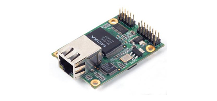
Of course, this is far from the only option: there are converters manufactured under the trademarks WIZnet, TIBBO ( UPD: colleagues also recommend Lantronix in the comments). And in addition to converters, I accidentally discovered another type of device, and even dedicated a spoiler to it later in the text (read, it's worth it ;-)
So, it turned out to be easier for me to order “moss” in the nearest store, and the brand has been verified. As it turned out, it works on the good old i80186 and seems to use the BSD IP stack. By the way, the NE-4110S has a programmable brother, its name is NE-4110S-P , and the Network Enabler SDK is also available to it . Stabout it, “brother” is one and a half times more expensive than “sister”, it is sold less often, and it still doesn’t save you from writing firmware. Therefore, I did not order the "brother." And, cheers, another childhood dream has practically come true: "to work on 80186." I always somehow lacked this missing link in evolution ...
Flashback from the funny 90s
I found IBM PS / 2 with i8086, sculpted on assembler IBM PC / XT with i8088 (on that old monitor, perhaps I could put a match in between the pixels). I played on the i80286 (both on AT and XT; and how juicy the VGA graphics seemed then!).
But for a long time the thought haunted: where the hell did the 186th go? What kind of processor beneladen is this?
In the days of FidoNet, there was such a company, US Robotics, known for Sportster and Courier modems. They were like two brothers: the younger Sportster (for home) and the older Courier (for business), and both are built on the i80186.
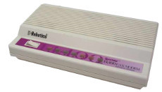
The budget "soap box" Sportster 14400, but to overclock on it more than 9600 was a success; was still green 28800
Since the x86 command system was widely known in certain circles, orders of flasher magicians appeared at that time, with their spells capable of turning a cheap Sportster soap box into a Courier, a kind of bulldozer for Russian off-road telephone, on the HST half-tracked caterpillar protocol . Internet did not exist, so frekat could and half-duplex. And what sounded like HST! Advanced users did not turn off the modem speaker to listen to modulation noise and retraindetermine the quality of communication. But at HST it was just a symphony: one could almost physically feel how the bitstreams at full speed dodge the floating logs of the old Soviet automatic telephone exchanges, as if guided by the skillful hand of an invisible captain. At as much as 16.8 kbit / s, but believe me, then it was not bad at all.
The bulldozer converted from the “soap box”, however, was buggy, and often turned out with one “transfer”: either only “forward” (to dial up) or to receive a call, depending on the DNA of the “soap box” (it’s really lucky). And therefore, before the advent of the Internet, all self-respecting fidos dreamed of getting a red-eyed telecommunication devil with the real Courier logo.

Telecommunications red-eyed devil, thunderstorm of all interference and a bulldozer of urban telephone networks
But only a few lucky ones fell asleep under the automatic queues of the courier relay of pulse dialing. The hardest part was for those with a boss’s phone number that contained zeros, nines, and other particularly long and crackling combinations. True ninjas, of course, soldered silent reed switches , which were later echoed eloquently , provoking the burning envy of the owners of simple "soap dishes". And at the same time, everyone together dreamed that someday the New Era would come, and our city telephone exchanges would also begin to understand the tone dialing, as in very distant and very happy countries ...
Peers, take out a napkin and catch it with a mean tear ... Hi, 80186, not long ago saw each other.
But for a long time the thought haunted: where the hell did the 186th go? What kind of processor beneladen is this?
In the days of FidoNet, there was such a company, US Robotics, known for Sportster and Courier modems. They were like two brothers: the younger Sportster (for home) and the older Courier (for business), and both are built on the i80186.
The budget "soap box" Sportster 14400, but to overclock on it more than 9600 was a success; was still green 28800
Since the x86 command system was widely known in certain circles, orders of flasher magicians appeared at that time, with their spells capable of turning a cheap Sportster soap box into a Courier, a kind of bulldozer for Russian off-road telephone, on the HST half-tracked caterpillar protocol . Internet did not exist, so frekat could and half-duplex. And what sounded like HST! Advanced users did not turn off the modem speaker to listen to modulation noise and retraindetermine the quality of communication. But at HST it was just a symphony: one could almost physically feel how the bitstreams at full speed dodge the floating logs of the old Soviet automatic telephone exchanges, as if guided by the skillful hand of an invisible captain. At as much as 16.8 kbit / s, but believe me, then it was not bad at all.
The bulldozer converted from the “soap box”, however, was buggy, and often turned out with one “transfer”: either only “forward” (to dial up) or to receive a call, depending on the DNA of the “soap box” (it’s really lucky). And therefore, before the advent of the Internet, all self-respecting fidos dreamed of getting a red-eyed telecommunication devil with the real Courier logo.
Telecommunications red-eyed devil, thunderstorm of all interference and a bulldozer of urban telephone networks
But only a few lucky ones fell asleep under the automatic queues of the courier relay of pulse dialing. The hardest part was for those with a boss’s phone number that contained zeros, nines, and other particularly long and crackling combinations. True ninjas, of course, soldered silent reed switches , which were later echoed eloquently , provoking the burning envy of the owners of simple "soap dishes". And at the same time, everyone together dreamed that someday the New Era would come, and our city telephone exchanges would also begin to understand the tone dialing, as in very distant and very happy countries ...
Peers, take out a napkin and catch it with a mean tear ... Hi, 80186, not long ago saw each other.
So, while the dish I ordered crossed state borders, I discovered an interesting fact: it turns out that many interface converters provide digital I / O (GPIO or DIO) to the heap. Probably to control something, right?
Do I need a Druid Choir
The phrase "without Al Durillo" in some circles means something like a quality mark: they say, it’s not
Against programming MK
Did I do the right thing by evading microcontroller programming? It seems to be a simple transfer of bytes to and fro, and all in all for five minutes, as one friend of mine said. But a quick glance at the forums on the subject area, I quite vividly imagined a kind of encoding IP-server in assembler. I figured that I need at least two UARTs: one on the RS232 console, the second on direct communication with the host (do not reset the watchdog timer by IP!). Then he began to count the number of UART on MK used in the popular Ai Drobino models. With rare exceptions, it turned out only up to one. Therefore, I had to imagine pushing bits into a wire, a popular method of scientific foot cracking in AVR (bit bang, soft serial). Continuing the thought experiment, I put all this in parallel with an imaginary IP server in assembler ... Brr! No, this is already some kind of long and spicy Asian dish for the whole family, and I asked for a light, diet lunch for one person.
I do not impose my point of view, but there is a subjective feeling that interconnection is a very weak link in microcontrollers, sometimes exacerbated by a lack of elementary information security skills in hardcore hardware (the code is very vulnerable). Caesar is Caesar.
I do not impose my point of view, but there is a subjective feeling that interconnection is a very weak link in microcontrollers, sometimes exacerbated by a lack of elementary information security skills in hardcore hardware (the code is very vulnerable). Caesar is Caesar.
For programming MK
For that matter, I personally think the STM32 platform with its stuffed peripherals seems more appropriate here. And once again I can not help but mention in this regard the EasyElectronics project . As you can imagine, Chelyabinsk electronics engineers are so harsh that they launch microcontrollers with their own finger. Doubt it? Read about FUSE and the finger method . If I give these guys a soldering iron (or put in a senior engineering position in a reputable concern), I’m generally afraid to imagine the consequences for the global electronics industry ...
There is a debug board for some kind of ambidextras of microelectronics, with interchangeable mezzanines AVR, STM32, PIC and FPGA. But I’m asking you to look not at the board itself, but at an inconspicuous productLAN Ethernet Adapter on ENC28J60 . The point is that on the back of the LAN Ethernet Adapter there is a socket for the same AVR or STM32 mezzanine board. On board, you get all the necessary harness for the MK, the USART legs from STM32 are also brought out to the pin connectors. For the task to be solved, it remains to screw the adapters from USART to RS232 and USB, to supply the device with power. Perhaps PoE, coupled with a more heat-resistant design and vibration protection, will not hurt for industrial needs , but this is another story ...
It would seem that an almost finished product based on a programmable MK is already here, but ... who will breathe life into it? No one canceled the firmware, and this is entertainment for the mythical man-month. Nothing is impossible, but you go to a restaurant to have lunch and not live a week or two, right? Think about it while on the shore ...
I will not mess with MK, I’ll always have enough time. Here, by the way, from a recent one: habrahabr.ru/post/208026
And under my good comic names, the reader, of course, easily recognized the popular platform used by both amateurs and professionals around the world. The market itself puts everything in its place ...
So, with the task of Serial-over-LAN everything is clear, but we will supplement our main menu of technical requirements with the first course:
2. Remote server reset using the RESET line on the motherboard
Let's see what has already been done on this topic . As soon as I saw the post of the noble don workDNK, how the knowledge store received at the institute came to life and applied for a job. Dear don, quite rightly put the opto-relay directly on the digital output of the MK, but my moss got bad luck. Page 3-8 NE-4100 Users Manual very explicitly hints:
The output current for digital output channels carries only 1 mA.Those. unlike the PIC18F1320-I / P, the digital port on the Moss will not squeeze more than 1mA from itself, and the opto-relay needs to be opened more than ten times for reliable opening. Then a transistor switch suddenly appears from the distant back streets of memory (I was surprised because the last time it was fifteen years ago). Throw a sketch diagram directly into the toaster standing next to the hub , and what do you think? Almost immediately, we get a couple of useful answers from noble dons. Mr. Gates himself would probably have dropped a tear here (you don’t think anything like that, this is his famous speech about information at your fingertips).
In theory, everything is quite simple, and I almost stopped there; but appetite is known to come with eating.
Is it possible to control offPC? Of course you can. Moreover, we do this all the time by pressing a large button on the PC case (for someone it is small and not on the case, and not on the PC, but that’s not the point). Even the simplest ATX power supplies have a + 5VSB line that powers the motherboard in the STANDBY state (power switch on, computer off; UPD: also called standby power ). Turning on the PC from the keyboard is all from the same place. By the way, in STANDBY on some motherboards you can even burn something by rearranging the memory bars, but this is not about that now. Usually the power in STANDBY mode is about 10W, but enough to power our controller, tea is not a hadron collider. Therefore, add a salad and side dish:
3. Independent power supply of the controller in STANDBY mode
4. Remotely powering the host on and off using the PWR_BTN line An
attentive reader, of course, will object to point 4: what about Wake-on-LAN ? And he will be absolutely right: indeed, even the most ordinary motherboard today allows you to wake a computer from hibernation with a special network packet. And by the way, do not look for ethtool in FreeNAS, ifconfig (8) is used for these purposes . All this is quite popular and therefore well chewed, there are examples of settings for popular home routers, a launcher utility for Linux, and much more. Well, you can’t order a side dish, I don’t insist. But I’m not going to leave the reader without dessert either.
For sweet today we have
5. Remote monitoring of power on with full preservation of the visual indicator functions on the chassis
My server does not respond to ping ... Haha, check
Our RESET and PWR_BTN buttons must be released for normal computer operation, but in theory it can either break through the transistor or the enemy send an incorrect logical signal. As a result, our controller will unauthorizedly close the optical relay, and the buttons will be, so to speak, “normally pressed”. I would like to defend myself against this without examining our hypothetical board. Also, at the debugging stage, we want to visually control what is happening. Therefore, do not forget about salt, pepper and other seasonings to our table:
6. Hardware blocking of the RESET and PWR_BTN control lines
7. Control LEDs on the RESET and PWR_BTN lines
8. Duplicate LEDs on the LED_100M and LED_10M lines
And the compote?
9. Visual monitoring of controller readiness (READY_LED) on the PC case through the HDD_LED indicator That
is a glowing (red) indicator of (disk activity) on the PC case will indicate that the controller is working (the PC switch is turned on, there is power). The green PC indicator retains its function and lights up only when the server is running. If everything is completely bad, you can call the site and read the LED readings using the
Here's what happened (forgive my readers some non-ghosts):
Scheme
Schematic diagram of the onboard control controller; if finely open the image separately
Schematic diagram of the onboard control controller; if finely open the image separately
Comment for beginner electronics
Make sure the top spoiler with the circuit is open. Go.
The core of the scheme: a small square in the middle left is like a J2 MOXA NE-4110S connector, it all starts with it.
The limiting resistors R4, R7, R8 for LEDs and R1, R2 for opto-relays are considered (you will not believe it!) According to Ohm's law. To open the opto-relay and light the LED (but not burn it to death!), A current of about 10 mA is needed. We proceed from the fact that a diode will drop from one and a half to two volts (we look at the current and voltage in the characteristics of the devices). Since the power bus gives 5V, the resistor needs to “lose” 3V at a current of 10mA, i.e. need resistance of the order of 300 ohms. Nothing complicated, and without calculators. Excuse me, where did the limiting resistor for the opto-relay along the PWR_LED line go? There, where for the READY_LED indicator (HDD_LED): they are both built into the schemes of our finished products, one on the motherboard, the second on the moss. No cheating.
The pull-up resistors R3, R5, R6 (see wikipedia ) with a nominal value of 10k. We will tighten the logical levels so that they do not hang out in the air and catch us from there.
Transistor keys. To solve the problem with a lack of control current (it takes 10mA, but there is only 1mA), put a key pair 2N7000. Field-effect transistors are voltage-controlled devices: when “moss” gives a high level, the transistor gate opens, but it practically does not consume current. At the same time, the drain-source circuit is closed, and electricity runs to itself from the + 5V bus through the limiting resistor to the ground, lighting the LED on the way, or opening the opto-relay. Polevik - a good device, only static electricity is afraid to death in the literal sense.
Optoreldual unidirectional, normally open. This useful device allows you to close (or open in a normally closed case) electrical circuits, while isolating them from each other. The control current is supplied according to the same laws as the LED, through a limiting resistor. Our relay is unidirectional: this means that the controlled (guided) current through it can be launched in exactly one direction: the “plus” must be connected to pin No. 6 or No. 8, otherwise the current will not work, the relay will seem to be closed. Optorelay is also afraid of electrostatics.
As you can see, this is not a quantum theory at all.
Well, let me remind you at the end that we are dealing with a built-in unpackaged product. If it is not fixed properly, if you jerk a jerk over the Ethernet cable, our controller will chat in the PC case, like underpants in a washing machine . To prevent this from happening, we’ll submit the cutlery:
10. Ethernet port rigidly fixed on the computer case. We
managed to solve the problem as follows:
Why do we really need internal 10 / 100BaseT modems and PCI adapters
It turns out there is a great use for old, unnecessary PCI boards with square connectors.
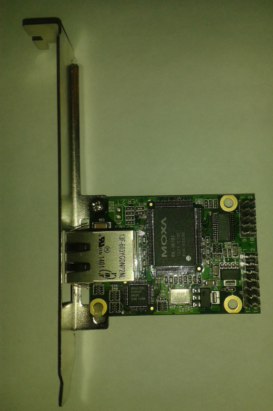
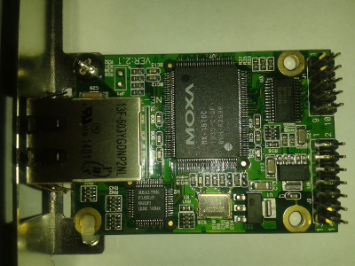
The interface converter on the bracket from the internal PCI modem
, of course, the distance between the mounting holes on the “moss” did not coincide with the bracket, so instead of the second bolt I used the usual nylon tie: it holds tight enough, and a wide window for two telephone jacks made it comfortable to place RJ -45 from the "moss".
Instead of the second bolt, a tightly tightened nylon screed
If you didn’t have an internal PCI modem at hand (it happens), the bracket from the PCI network adapter would fit (10 or 100 megabits are best, but 1000 is also possible). The tolerance for the placement of the bolts, of course, will be somewhat different, but nothing is impossible.
So, your order has been accepted, we prepare the dishes and proceed to the meal!
Another interesting remote access solution
Being engaged in summer Internet, I came across a modest product TP-LINK MR3020 .

This, at first glance, a frivolous pocket router the size of a small packet of cookies can turn into a multi-purpose remote access platform with features that the manufacturer of the product was not even aware of. Under the case, he has Atheros AR7240 @ 400MHz, 4MB flash memory, 32MB RAM, and also (with some ingenuity and soldering iron ) a serial port and GPIO . Communication with the world via a USB modem, Ethernet or WiFi (although the built-in antenna is rather weak). Find out how many more interesting things you can get for only $ 25: http://wiki.openwrt.org/toh/tp-link/tl-mr3020 . By the way, USB modems come with microSD (read just in casepost about flash memory and get some knowledge of Linux, they will be very handy).
In principle, this thing can be stuck spyly inside the PC case, powered by the same + 5VSB and connected to the serial port (note: there is a TTL level, an adapter is needed for RS232, and an adapter is needed for USB plus OS support). Just watch for security, remote access is a double-edged sword, and the word "spy" is not just like that ...
UPD: the device is sung on the habra habrahabr.ru/post/151982
In order not to mess with aggressive environments, a soldering iron and its other iron (these are not heroes from the 90s, as the boards are doing at home now), but to run everything on real hardware, I decided to assemble my simple product on a solderless breadboard ( breadboard). By the way, a very practical thing, especially for those who are on the "you" with a soldering iron. As for the home-made breadboard jumpers, I respect professionals, but I do not like all these “explosions on the telephone switchboard", so I bought a beautiful branded set of different-sized jumpers.
Heartbreaking scene
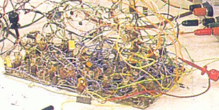
Depressant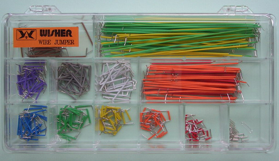
Set “tired IT specialist” for stress relief
Set “tired IT specialist” for stress relief
Although the jumpers cost money, you can sit for hours and stick them in the breadboard and so on, choosing the optimal length. This is such a special therapy for the stressed out workers of the information workshop, it calms down no worse than gluing ships with airplanes: there is neither white-orange, nor white-green, nor white-blue, nor white-brown, everything is specially plain. More stress-resistant colleagues can, of course, cut the jumpers from a single-core twisted pair, the section is suitable.
In general, I recommend that beginners read the best-selling book: habrahabr.ru/post/148656 , after which I could hardly resist buying the entire range of the nearest amateur radio store.
Layout of a solderless breadboard in a free notation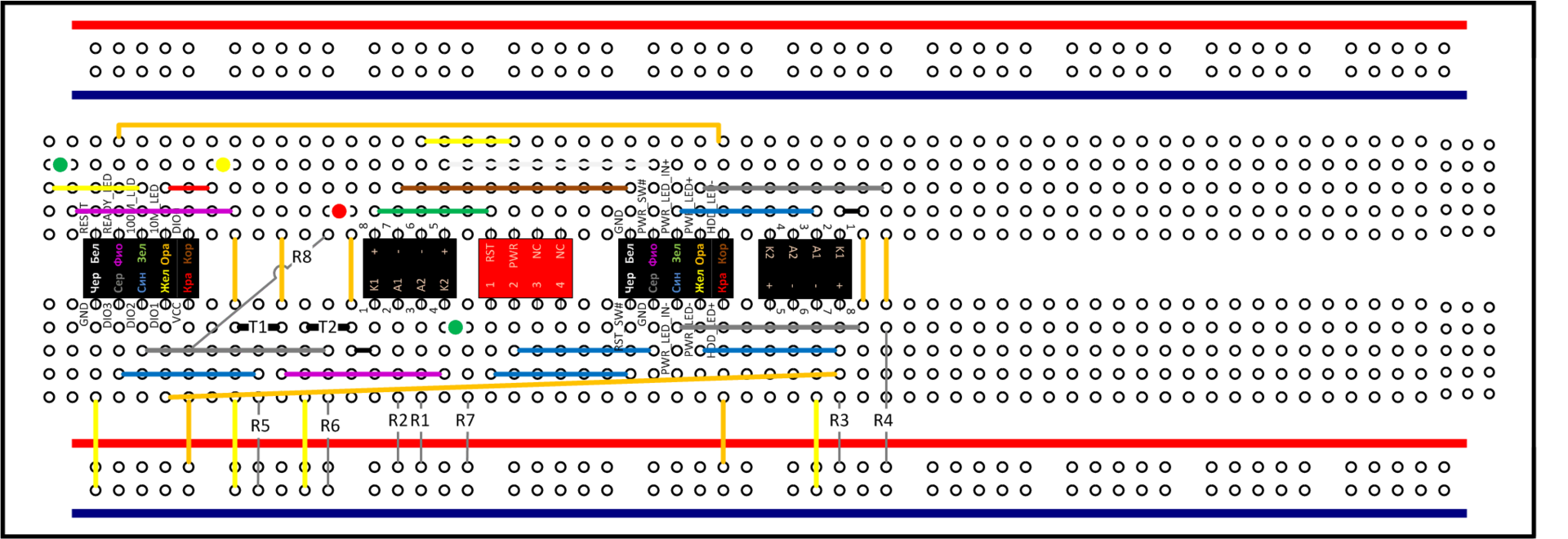
The stencil for Visio was taken from here: www.sandrila.co.uk/articles/visio-articles/electronics-breadboards
The stencil for Visio was taken from here: www.sandrila.co.uk/articles/visio-articles/electronics-breadboards
By the way, if someone wants to make this in the form of a real board, let me know in PM, maybe I will even take part.
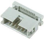
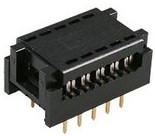
Surely this is not news, but along the way I found a (literally) cool way to pair the solderless breadboard with the world around with connectors on a flat cable (Insulation-Displacement Connector, IDC): we pin a DIP type connector on one end of the cable (with a pitch of 2.54mm, it goes into breadboard), and the other end we disassemble and crimp with a crimper, then shoe the necessary pin connector BLS / BLD (crimping pliers I use the same as in another post ). Or we do not divide the loop, but just prick another IDC connector. You can chop them a lot, like on cables for old IDE disks. About how many wonderful discoveries an electronics store is preparing.
According to this principle, I assembled two cables: one (simple) for connecting my motherboard to the MOXA NE-4110S, and the second (tricky) for pairing with the connectors on the motherboard. I highly recommend the color loop: it will not only please the eye with a cheerful rainbow of color marking, but for non-standard tasks it will also greatly save the expensive resources of your central nervous system, freeing it for more interesting tasks. A boring gray train is good for simple and direct options, it is better not to execute any inverted figures on it.
If anyone has not seen the fun
Color fun train
Color fun train
This IDC plug connector with a pitch of 2.54 mm is punctured at the end of the
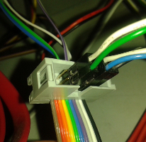
cable far from the breadboard. Tricky cable
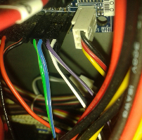
Left: connect the buttons and LEDs from the PC case to the plug (IDC connector) on the cable; from the connector further go two pairs ...
Cprava: two pairs reached the standard contacts and RST_SW PWR_SW on the motherboard, nearly all the required chain locked
These two IDC connector (2.54mm pitch) prick on the proximal end of the loop, they "sit" on the breadboard
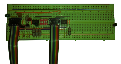
breadboard board with two connected loops.
Installation is concentrated on the left, and on the right edge the Spare Property of the Device sticks out alone (field effect transistor, if it breaks through the existing one). In my opinion, it turned out neatly, even despite the cyclopean dimensions of the limiting resistors (your humble servant was a little hasty when purchasing).
About proper nutrition
To fulfill the requirement No. 3 for independent power supply in STANDBY mode, we look for something suitable on the motherboard. Well no incision and tsya same 20-pin ATX power connector, in fact. That's luck: judging by page 17 of the P4i65G manual , the completely useless infrared port is powered by the + 5VSB line (looking ahead, I note that this turned out to be a cynical trick). Well, add to the basket the corresponding 2-row 6-pin connector with 2.54mm pitch, sometimes referred to as BLD 2x3.
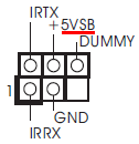
Almost useless connector for connecting IR devices to the motherboard P4i65G, BLD 2x3
By the way, if the reader suddenly wants + 5VSB (aka standby power, thanks to the commentators), I would recommend looking somewhere on the internal USB connectors, or on the PS / 2 keyboard connector. Go to the BIOS power management section and see what the computer might wake up from. Those devices that are able to pull the computer out of the shutdown are connected with the “standby” + 5VSB.
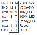
J2 connector on MOXA NE-4110S, BLD 2x7
In addition to the J1 serial port in the RS232 standard (an analogue of what sticks out on motherboards), the moss also has an explicit J2 connector for connecting power, GPIO (DIO), control LEDs and debug serial TTL level ports (TXD1, RXD1, GND). Just in case, I will say that TTL UART requires a linear driver to interface with RS232, there are different voltages; but we will not connect and use this port. Just add to the purchases a 14-pin female connector with a known pitch of 2.54mm (1/10 ").
Stop, why does the moss have two VCC + 5V contacts? Having read the dispensaryAbout the delicious and healthy nutrition of microcontrollers, I already began to suspect a separate bus. But having seen a very unambiguous spike on the board in front of the only voltage regulator (and even having measured its resistance just in case), I realized that such a double input of power to the internal wiring is irrelevant. Therefore, we turn the situation for our own selfish purposes: we bring power to + 5VSB to one contact, and from the other we immediately take it to our breadboard. And the wolves are whole, and the sheep are full. Maybe for me they left these two contacts?
A bit about electrostatics
The last time I was on the radio market, probably in the late 90s. Recently, I didn’t know anything at all about the solderless mock-ups, nor about the AVR and their Broken Chorus. All this immersion in microelectronics took about two weeks in hobby mode, during which I had to read a lot.
At the same time, I decided to first pass the mock-up test to myself, having bought a 7-segment indicator for exercises and any mikruha with loose powder. It is clear that instead of a common cathode, I took a common anode, and when connected to the 4511 chip, my indicator showed numbers inverted and required a lot of transistors. It’s good that nobody saw my microelectronic bullying ...
Not only from laziness, but for the sake of experiment, I decided to almost completely neglect electrostatic safety, taking a pair of protective tweezers and a dozen field-effect transistors in reserve. And he looked into the water: in the process of passing the test, the death of the brave already killed seven out of ten "field workers". Conclusion: if you work with field-effect transistors or other CMOS components, protect the legs of these delicate devices from electrostatics, the reality of the problem is now confirmed by another experiment. There are many protection options: from ritual foil wrapping in what the mother gave birth to special bracelets and rugs. Only if there is no real “land” in the apartment, please note that during your electronic meditations, some kind neighbor, according to the laws of the genre,will necessarily drop the phaseground the washing machine to the same pipe. And then, if your defense itself is not protected, then you can inadvertently get a virtual reality helmet from a foil cap, as in one long-forgotten fidoshoe button accordion (then there was no concept of "I patstalom", but now I know what it's called). Personally, I preferred to pay with a pair of tweezers and a few punched transistors (eternal memory to them). And forgive me, electronic monsters. But seriously, google an electrostatic bracelet on a topic .
At the same time, I decided to first pass the mock-up test to myself, having bought a 7-segment indicator for exercises and any mikruha with loose powder. It is clear that instead of a common cathode, I took a common anode, and when connected to the 4511 chip, my indicator showed numbers inverted and required a lot of transistors. It’s good that nobody saw my microelectronic bullying ...
Not only from laziness, but for the sake of experiment, I decided to almost completely neglect electrostatic safety, taking a pair of protective tweezers and a dozen field-effect transistors in reserve. And he looked into the water: in the process of passing the test, the death of the brave already killed seven out of ten "field workers". Conclusion: if you work with field-effect transistors or other CMOS components, protect the legs of these delicate devices from electrostatics, the reality of the problem is now confirmed by another experiment. There are many protection options: from ritual foil wrapping in what the mother gave birth to special bracelets and rugs. Only if there is no real “land” in the apartment, please note that during your electronic meditations, some kind neighbor, according to the laws of the genre,
Security
But let us not forget about doors, windows, and the like. Our NE-4110S does not lock with passwords, but can use simple ACLs to IP addresses, which are recommended to be limited to the administrative network. The server operating system must necessarily request a login and password to enter through the serial port. All the contents of Serial-over-LAN are transmitted over the network in clear text (telnet), so you can’t do this over public networks without encrypted VPNs (otherwise the root password will be gone, which you will probably enter). For the same reason, you need a separate VLAN (a simple Ethernet network switch with crowded ARP tables turns into a hub that starts ringing packets on all ports of the segment). All remote server access devices are potential vulnerabilities,
By the way, as some users have discovered, FreeNAS hasn’t gotten along well with the serial console implementation around the 9.2.x release ( https://bugs.freenas.org/issues/4266 ). Be careful if using this system.
Lazy null modem
I made a null-modem RS232 cable for connecting the serial ports of the server and the controller from a cord from a disabled card reader, to which Business had dislocated a dozen legs some time ago. I had to order new 2-row 10-pin connectors of the type "mother", because the old protection from the fool (in the form of a “flooded leg”) just did not let us connect the USB cable to the COM port connector. You can easily make such a cable from a flat cable, I'm just lazy, and so I took the finished cord, I had to crimp with a crimper just a couple of wires instead of two dozen. Again, I recommend the reader to use a fun color loop for such tasks.
Full null modem cable diagram, borrowed from bogpeople.com/networking/SerialComms/rs232pinouts.shtml
The question is: are all these DTR, DSR, RTS, CTS necessary? And anyway, why a DCD in a null modem? Once upon a time, I connected the console to the Frame Relay switch with three wires (RXD, TXD, GND) over a twisted pair cable, and everything worked. But look at the serial console device in FreeNAS. It uses records like freenas_serial9600 from gettytab (5), and at the same time the sign of `` nc '' is not visible there. But in theory, this means that in the absence of a DCD signal, the serial port will be considered “dead” and the console will not go through it, at least without interfering with the FreeNAS code. I may be mistaken and not take into account the electrical properties of the line hanging in the air, but Crepsondo's philosophical practices recommend that in such cases it is necessary to crimp the DCD line, and not to patch the FreeNAS firmware on the read-only file system, then sweating with each remote server upgrade. Do not read stories on the Internet about non-standard null modems, do a standard one. Then come in handy somewhere else.
So, I’ll give a null modem crimping circuit to a view of an imaginary 10-pin female connector, sitting on an imaginary cable. The circuit, by the way, at the time of testing almost brought me toZugunder , but more on that later.
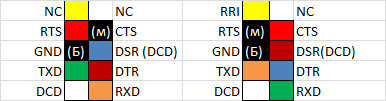
Diagram of a null modem, view of the “mother” type connectors, color coding of the USB cable (two black ones: one thicker, the second thinner)
Software
Brothers, look at the length of this post, and we are not even going to program the microcontroller! Nevertheless, I will add the simplest perl script for remote button presses to complete the story. He is a little redundant, but it is for beauty.
Sending a second press on the power button
#!/usr/bin/perl
use IO::Socket::INET;
$|=1; #flush
my $s = new IO::Socket::INET (
        PeerHost => '10.100.200.1', # NE-4110S host
        PeerPort => 5001, # DIO port
        Proto => 'tcp',
) or die "IO::Socket::INET: $!\n";
my $CMD_PWR_ACTIVE = pack('C7',
        2,      # command number, fixed
        2,      # version, fixed
        0,      # this byte is only used in response
        3,      # data length, fixed
        3,      # desired DIO channel number
        1,      # 1: set to output mode
        1,      # 1: set to high
        );
my $CMD_PWR_INACTIVE = pack('C7',
        2,      # command number, fixed
        2,      # version, fixed
        0,      # this byte is only used in response
        3,      # data length, fixed
        3,      # desired DIO channel number
        1,      # 1: set to output mode
        0,      # 0: set to low
        );
my $res;
my ($hdr_cmd, $hdr_ver, $hdr_err, $hdr_len);
my @data;
print "PWR_ACTIVE\n";
print $s $CMD_PWR_ACTIVE;
$s->recv($res, 4);
($hdr_cmd, $hdr_ver, $hdr_err, $hdr_len) = unpack('C4', $res);
printf("result: CMD %d VER %d ERR %d LEN %d\n", $hdr_cmd, $hdr_ver, $hdr_err, $hdr_len);
$s->recv($res, $hdr_len);
@data = unpack("C$hdr_len", $res);
sleep(1);
print "PWR_INACTIVE\n";
print $s $CMD_PWR_INACTIVE;
$s->recv($res, 4);
($hdr_cmd, $hdr_ver, $hdr_err, $hdr_len) = unpack('C4', $res);
printf("result: CMD %d VER %d ERR %d LEN %d\n", $hdr_cmd, $hdr_ver, $hdr_err, $hdr_len);
$s->recv($res, $hdr_len);
@data = unpack("C$hdr_len", $res);
sleep(1);
$s->close();
exit(0);
Sending a second press on the RESET button
#!/usr/bin/perl
use IO::Socket::INET;
$|=1; #flush
my $s = new IO::Socket::INET (
        PeerHost => '10.100.200.1', # NE-4110S host
        PeerPort => 5001, # DIO port
        Proto => 'tcp',
) or die "IO::Socket::INET: $!\n";
my $CMD_RST_ACTIVE = pack('C7',
        2,      # command number, fixed
        2,      # version, fixed
        0,      # this byte is only used in response
        3,      # data length, fixed
        2,      # desired DIO channel number
        1,      # 1: set to output mode
        1,      # 1: set to high
        );
my $CMD_RST_INACTIVE = pack('C7',
        2,      # command number, fixed
        2,      # version, fixed
        0,      # this byte is only used in response
        3,      # data length, fixed
        2,      # desired DIO channel number
        1,      # 1: set to output mode
        0,      # 0: set to low
        );
my $res;
my ($hdr_cmd, $hdr_ver, $hdr_err, $hdr_len);
my @data;
print "RST_ACTIVE\n";
print $s $CMD_RST_ACTIVE;
$s->recv($res, 4);
($hdr_cmd, $hdr_ver, $hdr_err, $hdr_len) = unpack('C4', $res);
printf("result: CMD %d VER %d ERR %d LEN %d\n", $hdr_cmd, $hdr_ver, $hdr_err, $hdr_len);
$s->recv($res, $hdr_len);
@data = unpack("C$hdr_len", $res);
sleep(1);
print "RST_INACTIVE\n";
print $s $CMD_RST_INACTIVE;
$s->recv($res, 4);
($hdr_cmd, $hdr_ver, $hdr_err, $hdr_len) = unpack('C4', $res);
printf("result: CMD %d VER %d ERR %d LEN %d\n", $hdr_cmd, $hdr_ver, $hdr_err, $hdr_len);
$s->recv($res, $hdr_len);
@data = unpack("C$hdr_len", $res);
sleep(1);
$s->close();
exit(0);
Equipment
List of ingredients with prices.
All devices in the DIP, or in the "output" (not SMD, not planar) cases - for solderless breadboard
| Name | Qty | Cost |
|---|---|---|
| MOXA NE-4110S Interface Converter | 1 PC. | $ 50 |
| Solderless breadboard | 1 PC. | from $ 10 |
| Dual opto-relay KR293KP4B, DIP8 package | 2 pcs. | $ 4 |
| Field Effect Transistor 2N7000, TO92 package | 2 pcs. | $ 1 |
| Limiting resistor 330 Ohm 5%, "output" housing | 5 pieces. | $ 0.30 |
| Подтягивающий резистор 10кОм 5%, «выводной» корпус | 3шт. | $0.20 |
| Светодиод красный АЛ307ЛМ d=5мм | 1шт. | $0.30 |
| Светодиод желтый АЛ307ЖМ d=5мм | 1шт. | $0.30 |
| Светодиод зелёный АЛ307НМ d=5мм | 2шт. | $0.60 |
| Переключатель DIP, 4 контакта | 1шт. | $1 |
| Разъем-вилка 2.54мм IDC (на шлейф), двухрядный 10 контактов | 1шт. | $0.50 |
| Разъем DIP IDC (на шлейф), 10 контактов | 2шт. | $0.50 |
| Шлейф цветной, 10 контактов | 1м | $2.40 |
| Разъём-гнездо 2.54мм на кабель BLD 2x7 (для MOXA J2) | 1шт. | $0.50 |
| Разъём-гнездо 2.54мм на кабель BLD 2x5 (для COM-порта) | 2шт. | $1 |
| Разъём-гнездо 2.54мм на кабель BLD 2x3 (для IR-порта) | 1шт. | $0.30 |
| Разъём-гнездо 2.54мм на кабель BLS 2x1 (для подключения к мат. плате) | 3шт. | $0.45 |
| Ненужная плата внутр. модема PCI | завалялась | |
| Маленькая нейлоновая стяжка | была | |
| Клещи для обжима контактов разъёмов BLS и BLD | тоже были, но вообще от $20 | |
| Патч-корд Cat5e | нашёл;) | |
| Перемычки для макетной платы | купите или сделайте сами | |
| Время | не считается | |
| ИТОГО | чуть дороже $70 | |
All devices in the DIP, or in the "output" (not SMD, not planar) cases - for solderless breadboard
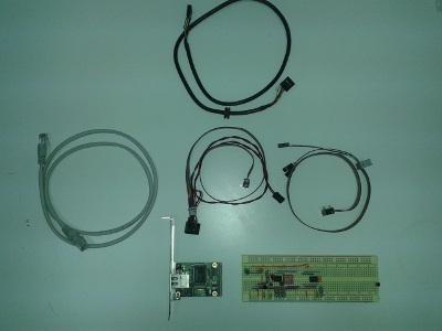
MOXA NE-4110S converter (on bracket), as well as board and cables
Spirit of experiment
Friday evening. Humming a little at low speeds of fans, methodically sucks our office worker Zeus by the nearby office dust, sheltered on her back a hugging couple from a switch and a home router. All data saved. All users are dispersed to homes and taverns. The LEDs are blinking comfortably, and the Spirit of the Experiment is already in the air.
First of all, replace the home router with a wild one . This, of course, is a separate story; It is worth saying that the brought wild router is already completely tamed at the stand: all the firmwares are updated, all settings, addresses, passwords, appearances and firewalls are set. We spend several minutes fussing around with wires, and everything went right the first time. Ah, what a fellow I am. Home router will go to the country.
Then we return to the main purpose of the visit and try to implement the original plan, relying on the availability of the promised + 5VSB on the infrared port.
We get our constructor, assemble and turn it on. It is dark and quiet, but it still smells not of smoke, but still the spirit of the experiment. We are looking for jumper PS2_USB_PWR1. Hell, she's under the cooler duct. Having taken our controlled traction vector for a while (see habrahabr.ru/post/214707 ), we try this way and that. Nothing happens.
As they say, finally read the instructions. On page 26 of the P4i65GSection 3.3.3 of the ACPI Configuration of the devices mentioned Ring-In (modem), PCI (Wake-on-LAN) and PS / 2 (keyboard). The IR port is not explicitly mentioned. Hm. And not a word about USB at all. Ok, try the PS / 2 keyboard. When the jumper PS2_USB_PWR1 is in the correct position, the PS / 2 keyboard in STANDBY mode really lights up and wakes the computer from hibernation. Yeah, as a last resort, we’ll borrow power from the PS / 2. The USB keyboard in STANDBY mode is deaf, like a fish on a fence, and the computer clearly does not want to wake up. So, the name of the jumper PS2_ USB _PWR1 should be read as PS2_PWR1, and the promised + 5VSB on the IR connector - as a joke of the manufacturer. USB in STANDBY state does not power this motherboard at all. Apparently, the developers thought that no one would notice such a cynical swindle.
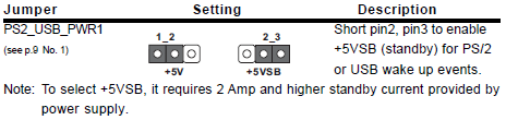
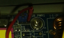
Jumper PS2_USB_PWR1, which actually has nothing to do with USB
But how can we power our household without unaesthetic snot sticking out of the PS / 2 outside the case? We remove the jumper PS2_USB_PWR1 completely and connect the power of our circuit to pin 3. Turn on. The server squealed somewhat indignantly and indignantly, and it seems that it is not going to start. And already in the air, the faint Phantom of Chernobyl was thought ... The brain reflexively calculates the possible expense: one motherboard, one power supply, what else can you burn? Not deadly, but running on iron on Saturday, and even with the feeling of losing, was not part of the plans of the great combinator. Okay, quickly cut it out of harm's way and again look at our electronic rebus.
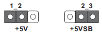
Electronic rebus: how many positions does the jumper have?
Something we did not take into account. Probably a five-volt power bus, on which the keyboard controller sits, and probably also half a dozen useful devices. Apparently, this is her entrance sticking out right under our nose in the form of contact number 2. On the left under No. 1, the output from the + 5V line, and on the right under No. 3 - the output from + 5VSB. Thank you, Captain Evidence, and where did you carry it on April 26, 1986. ? “Come to Kiev, you will be amazed !” - joked then one respectable gentleman. “Idiot, feed me a five-volt bus!” - the computer squeaked to me ...
Причём тут вообще авария на Чернобыльской АЭС? А вы вспомните себя в известной позе Данилы-мастера с каменным цветком: сколько раз приходилось доставать шаманский бубен, соединять бегемотов с носорогами и полагаться на авось? Сколько раз приходилось включать то, чего включать нельзя, и выключать то, что лучше бы вообще не трогать? Я недавно читал какое-то глобальное исследование, из которого достаточно чётко следовало: значительная часть аварий в ИТ-сфере происходит по вине персонала, в процессе того, что обычно принято называть регламентными работами. Этот айтишный авось не русский, он общемировой. Вот и меня понесло туда же. Авось, пронесёт...
Another random scheme
We put the jumper in position 1-2 (we give the usual + 5V to the bus), and we feed our product directly from pin No. 3 + 5VSB, borrowing the “ground” from the useless infrared port connector. Be sure to wrap the terminal in heat shrink or the BLS 1x1 connector (otherwise it will be short; this is usually not fatal, but the protection of the power supply will prevent the machine from starting). We take a deep breath and turn on the circuit breaker ... We exhale under the cheerful winking of the LED_100M LED. Fans and all other mechanics silently stand and wait. Telnet cheerfully displays the main menu of the controller. Hooray, now we really control the computer off! The ghost of Chernobyl melts safely in the air, leaving a whitish cloud of childhood memories. A curtain.
Stop, stop, what curtain? The reader knows very well that servers start so beautifully only in fairy tales. Therefore, yes, between turning on the switch and the result there was a half-hour crawl on the floor around the deaf serial port, accompanied by attempts to switch the speed / flow mode, scratching turnips and UNIX commands, interspersed with a mat. Because when crimping both ends of the cord, I looked at the same picture (both times to the left), collecting a regular straight cable instead of a null modem ...
One connector must be crimped on the left picture, and the other on the right; order is unimportant
Ugh! Having discovered such an epic jamb, I immediately perked up, squeezed a paper clip from the office stapler and began to straighten the connector back with it. Redid the cable as it should, I received the FreeNAS console menu as a reward. Zugunder passed. Of course, there was also the most magical moment of the check, when the box standing half a meter obediently stalled and came to life, obeying invisible commands from a server in a distant country. The control LEDs blinked, telemetry on the digital input (green LED) showed “down” when the server is on and “up” when it is off, and all this under the dumb but funny wink of the LED_100M indicator.
Apart from the jamb with a null modem cable, the experiment was a success the first time.
As required by Her Majesty Engineering.
In parting, another long-forgotten, but beloved button accordion from the 90s by an unknown author:
Было ортогонально
Мерно покачиваясь на волнах синусоиды, аргумент плавно скользит в бесконечность. Мимо стремительно проносятся гипотенузы и катеты. Со свистом пролетают пределы.
Медленно тащатся обратные тригонометрические функции, уступая дорогу важным Производным Высших порядков. По обочинам безмолвно стоят модули и флаговые подпространства. Изредка промелькнет и исчезнет, волоча за собой свой хвост, степенной ряд. На коротких ножках, подпрыгивая и спотыкаясь, бегут группы, алгебры, области D, Омега, сопровождаемые стайкой неугомонных идеалов.
Вектор нормали клонился к факториальности, фазовое пространство стремилось к предельной точке, уже супремум с инфинумом, пораскинув мощностью, аппроксимировались константой, сошки помельче, вроде директрисы и центра масс уже сколько угодно близко приблизились к малому числу Дельта, все плохие точки вытеснены без ограничения общности, распределение Дирака применено к системе со связями; приближалась сходимость. Еще не приведенные многочлены векторно умножались на матрицу перехода, а те, кто не успели, были задавлены экспонентой. Повсюду шастали волнистые координаты. Маленькие бесправные логарифмы гонялись за эпсилоном, беспомощно размахивая суммируемой особенностью.
Было ортогонально.
В наступившей неустойчивости там и сям раздавался хруст колец. На них действовала вторая квадратичная форма.
Фактор-пространство, донимаемое поточечной сходимостью, слонялось между двойными и повторными интегралами, которые гордо брались и аккуратно подбирали выражения в элементарных функциях.
Гомоморфизмы, выбрав уголок полокальнее, занимались любовью с матрицами Грама и Якоби.
Непрерывность шла своим чередом. Комплексные переменные — блюстители порядка, сужаясь на класс эквивалентности, раскладывались в ряд Фурье и быстро понижали порядок, если какой-нибудь условный экстремум, уделанный алгоритмом Евклида, пытался последовательностью зажать с двух сторон бесконечно малую. О-большое и о-малое, с точностью до величин первого порядка, оценивали условно сходящийся ряд. Мягкой периодичностью лилась тригонометрическая система функций. За ними вовсю ухлестывали обобщенные. Гладкость не менялась, линейность не нарушалась, сингулярность проявлялась только в точках накопления. Риманово многообразие подернулось дымкой субгармоничности, импликация с детерминантом молча удовлетворяли краевые условия.
The next step began. It will be followed by more and more, and so on, to infinity. This will continue until there is a delta for any epsilon, until the sums are Darboux, the rule is Lopital, the principle is Maximum Modulus. Until a new Gauss, Cauchy, Lagrange, Pythagoras, Fermat, Fourier, a new Ostrogradsky come and reveal a new, previously unknown knowledge, a
new Revelation, a
new Mathematics.
A curtain.