Draft accident alert info panel (Part 1)
Instead of intro
The history of the creation of the project might not have started if it weren't for the unpleasant “But” - the department has equipment that should work without fail, 24/7/365 (around the clock, seven days a week, always) - in fact, these are hardware stations ( optical multiplexers, SDH equipment) and SIP telephony servers (as well as the Call center, but the operators themselves tell us about this, they were very well trained to respond to the slightest failures).
The equipment itself is located in the server room, remote from the office, and is quite noisy (50-80db inside is normal, you even have to speak in raised tones, because otherwise you just don’t hear the interlocutor already half a meter away).
In the event of any equipment malfunctions, it is necessary to quickly eliminate them (malfunctions can occur both on our part and on the part of the connected operators, as well as for independent reasons, for example, optics breakage, line overload, other data loss), due to what you need to constantly do for performance indicators.
Measures are being taken, but previously this happened with some delay due to the lack of control.
Visual control of the equipment is possible (indication of warnings and accidents pre-morten), but this requires being close to the equipment, which is constantly not possible.
Interested, I ask for cat. (Caution, traffic ~ 10-15MB photo)
Content
Part 2
For those who are not interested in the background, you can safely skip it and go to the main idea of the post.
Preamble
Thus, to monitor the condition of the equipment, some kind of monitor was required. A conventional monitor is not suitable due to the complexity of visual control, as well as the lack of meaning in it. It is much easier to see if the red light is on, than to look for which indicators somewhere on the monitor have turned red, which are already red (the unconnected outputs of the optical converters display rather unpleasant accident indicators), and so on.
The first option was a complex of them:
- Virtual server (ubuntu 11.04, 512MB RAM, NoGUI).
- Scripts on the same server (written in Perl).
- Flashing warning devices.
Hardware characteristics of the current (working) warning device:
ATMega48 + Arlan 9000 + LED strip (1 sec.) 12V + IRLML2402 as a key.
The device works in byte standby mode on USART, echoes the same byte back, and checks what exactly has arrived.
If "1" - allows the timer interrupt to work (it fires about once per second, flips the pin that controls the MOSTFET key).
If "0" - prohibits its work.
In both cases, after exiting the interrupt, the MCU continues to wait for bytes from the USART.
It is powered by 12V with the simplest stabilizer KR142EN5A (5V at the output, which is more than enough to power the MCU and operate the low-voltage IRF key).
In the server side, everything is even simpler. CRON runs a script every minute (not even a script, rather a cycle to start the script itself and pause the wait), so that the interpreter starts every 10 seconds. There are few devices, so you can solve this problem head on.
The script sequentially checks the device status with SNMP requests, remembering the status. If at least somewhere the status of the accident returns, the symbol “1” is transmitted to the actuator. If everything is okay everywhere - “0” is transmitted.
Everything works, but not to say that it’s convenient - it’s unknown WHAT it feels bad.
[/ Background]
Now the main part.
At the moment, a more complete network notification device is being developed (although it will also work together with a virtual server and more advanced scripts).
The finished material will be posted in the relevant topic.
Current sources do not differ in beauty, therefore, they will not be laid out within the framework of the preliminary article.
The essence of the device:
MCU : ATMega1284p (chose what was available, literally on hand), quartz at 18.432MHz / RAM: 16kB, Flash: 128kB, EEPROM: 4kB, USART /;
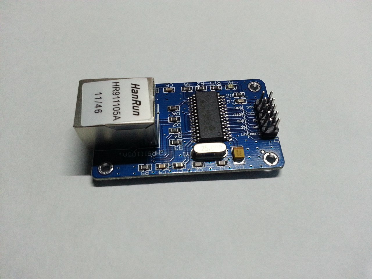
Ethernet module : ENC28J60; / Sources of the library and description of working with the module here /
Indication : 20 modules 8x8 LED DOT Matrix (purchased on E-Bay);
Sound: Piezo emitter, DAC 8bit R-2R on resistors, the sampling frequency will be ~ 22kHz, Single-tone signals;
Additional periphery : Thermometers DS12B20;
Power : \ At the moment, it’s a question, because I don’t want extra wires to the device, and I want to assemble it according to the POE scheme, but the finished module will not withstand 48V, therefore, 12V PSU will probably be used as a POE adapter \
As an internal power supply, and stabilizer, use the Step-Down DC-DC Converter module on the LM2596 (from the same E-Bay);
Debugging: UART in RS232 mode (at a speed of 115200), it is turned on only at the start of the MCU, if there is potential on the given MCU pin, otherwise it is not turned on and almost does not consume system resources;
Design
The device will constructively be an info panel (resembling those in buses), but with a smaller size (I could not find the original one - it doesn’t google what is presented on our buses, but it resembles a running line).
A similar dashboard on the bus
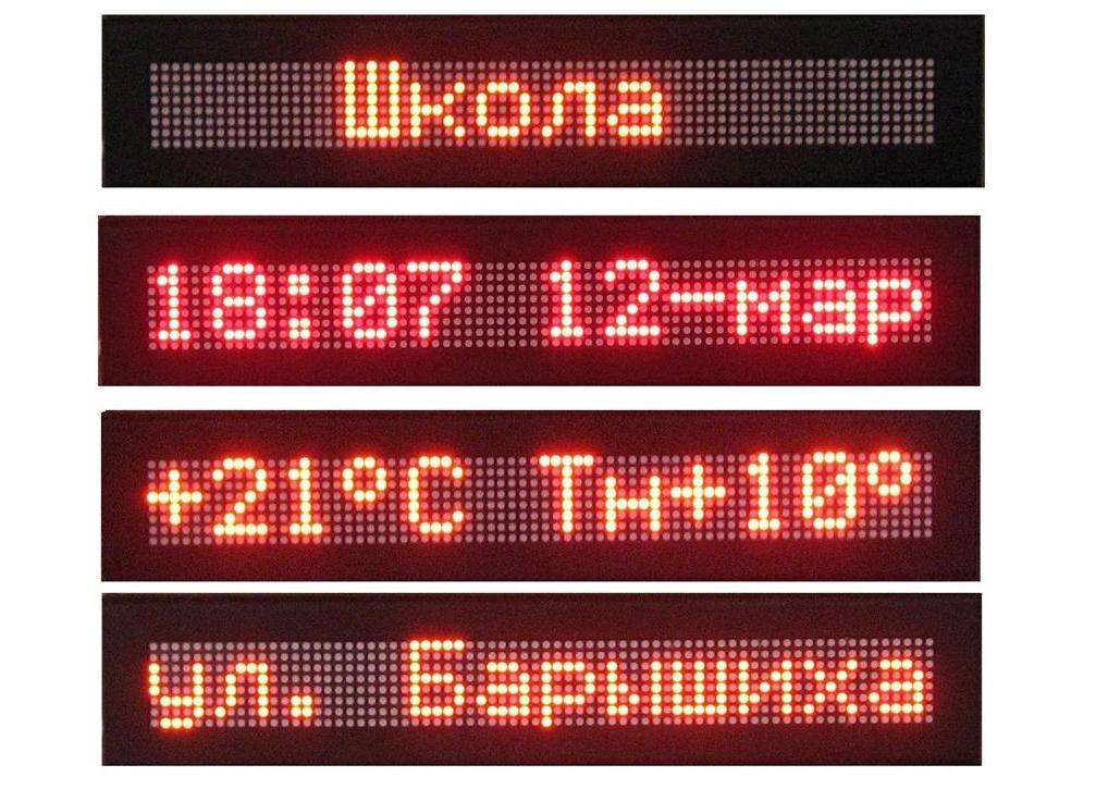
The finished device will have a visible area size of 20x400 mm (1 line for 20 modules), in the future it can become two-line, or increase the font (most likely the first).
It is planned to work in an Ethernet network (completely independent).
Organization of work in the Ethernet network occurs through the ENC28J60 module ( special thanks to the user easyelexnronix, Lifelover for the module driver, as well as examples of working with it ).
The possibility of sound notifications is planned (the presence and necessity of an audio signal is controlled by the server), as well as the ability to play streaming sound (decoding will also happen on the server side; the problem with playback and low processor power, as well as the complete absence of DMA, is solved by playing from ring buffer); text indication - dynamic.
So, in order:
Kernel
The MCU requires multitasking, and at the same time, hard real time (for sound), so an attempt was made to use FreeRTOS, but after calculating the overhead, I had to abandon such an undertaking. Sound playback of (relatively) high quality requires processing data at a frequency of 22 kHz (so as not to worry about resampling the sound), a significant part of the MCU resources will be required to switch tasks in this mode. At the standard frequency of system interrupts (100..1000Hz), PCM sound without DMA cannot be reproduced.
Sound Sound
processing occurs when the timer is interrupted. The same interruption, in the absence of data in the sound buffer, will itself disconnect itself.
A single-tone tweeter will be connected to the outputs of the PWM-generator, which does not exclude the possibility of the operation of only one piezoelectric emitter for alerts.
Audio interrupt handler
ISR (TIMER3_COMPA_vect)
{
#ifdef STREAM_SOUND
	cli();					// Disable interrupts
	if (plaing_now)				// If now plaing..
	{
		snd_R++;			// Increase read position,
		bytes_remain--;			// and decrease bytes remain count
		if(snd_R >= MAX_SND_BUFFER-1)	// Then if ReadPos reaches EndOfBuffer
		{
			snd_R = 0;		// Reset it.
		};
		if(bytes_remain <= 0)		// And if it's NO bytes remains..
		{
			plaing_now = 0;		// Stop plaing
			DAC_PORT = 0;		// And set DAC to ZERO.
		};
		DAC_PORT = snd_buffer[snd_R];	// Set DAC Value to Buffer[Read];
	};
	if (!plaing_now) {			// If interrupt triggered, but NOT plaing now..
		TCCR0B &= (0xF8);		// Disabling timer.
		TCNT0 = 0;			// And Reset timer's value.
	};
	sei();					// Enable interrupts.
#endif
};Indicator
The indicator implementation is planned on shift registers with latches 74HC595 (column driver + row driver) + IRLML2402 as a row driver (buffer).
Registers are used as a column driver because their current load allows you to power a whole line (8 points) at the same time.
These lines will be gradually pushed through the registers horizontally, starting from the "right" edge, so as not to bother with an additional frame buffer, and the entire image will be displayed line by line.
At the same time, the registers have a common data bus, but separate clock buses (+1 to the saved MCU pins).
A dynamic indication at a frequency of 125Hz should not be perceived by the eye as a flicker (referring to the total regeneration frequency), the switching frequency of the lines is 1kHz (a millisecond timer is used).
Due to the presence of latches in the registers, it will be possible to completely avoid flickering when switching lines (I will add a small pause of several clock cycles after the transition of the outputs of the registers to the Z-state, snapping new data and switching to the operating mode).
Power supply
As already mentioned, the power will come from outside to the ENC28J60 module, as its design allows you to remove voltage from 3 and 4 pairs of cable (they are not closed to the housing and are not connected to anything). Then this voltage will be supplied to the DC-DC converter and reduced to 5V.
At the moment, there is a question of voltage levels:
The core needs to be powered from 4.5-5V, because otherwise it is not guaranteed to operate at a frequency above 12MHz (valid for 3.3V), but the network interface must be powered from 3.3V, otherwise the chip is very hot, and there is a danger of its failure. There is only one converter available, therefore, an additional Low Drop 5V -> 3.3V is required for currents up to 250mA, again, preferably a pulsed one with high efficiency. In stock, unfortunately, no.
upd: I’m already advised to assemble the converter for scattering of elements and to power everything from a normal POE without restrictions in 12V. That's just in this circuitry, I have not yet been very lucky.
RTC support will likely be added to the final project (DS1307 ). In particular, I will try to describe the work with NTP (it will be ugly, but I will describe the basic functionality).
For one, I will again remember / learn the principles of data processing at different levels of OSI.
Currently there are:
- Partially assembled library (the network is visible, it remains to finish checking the availability of the link and data processors ... all ... a lot ..)
- Ethernet module ENC28J60
- Step-Down DC-DC Converter (LM2596)
- Indicators (unassembled) (20 pcs)
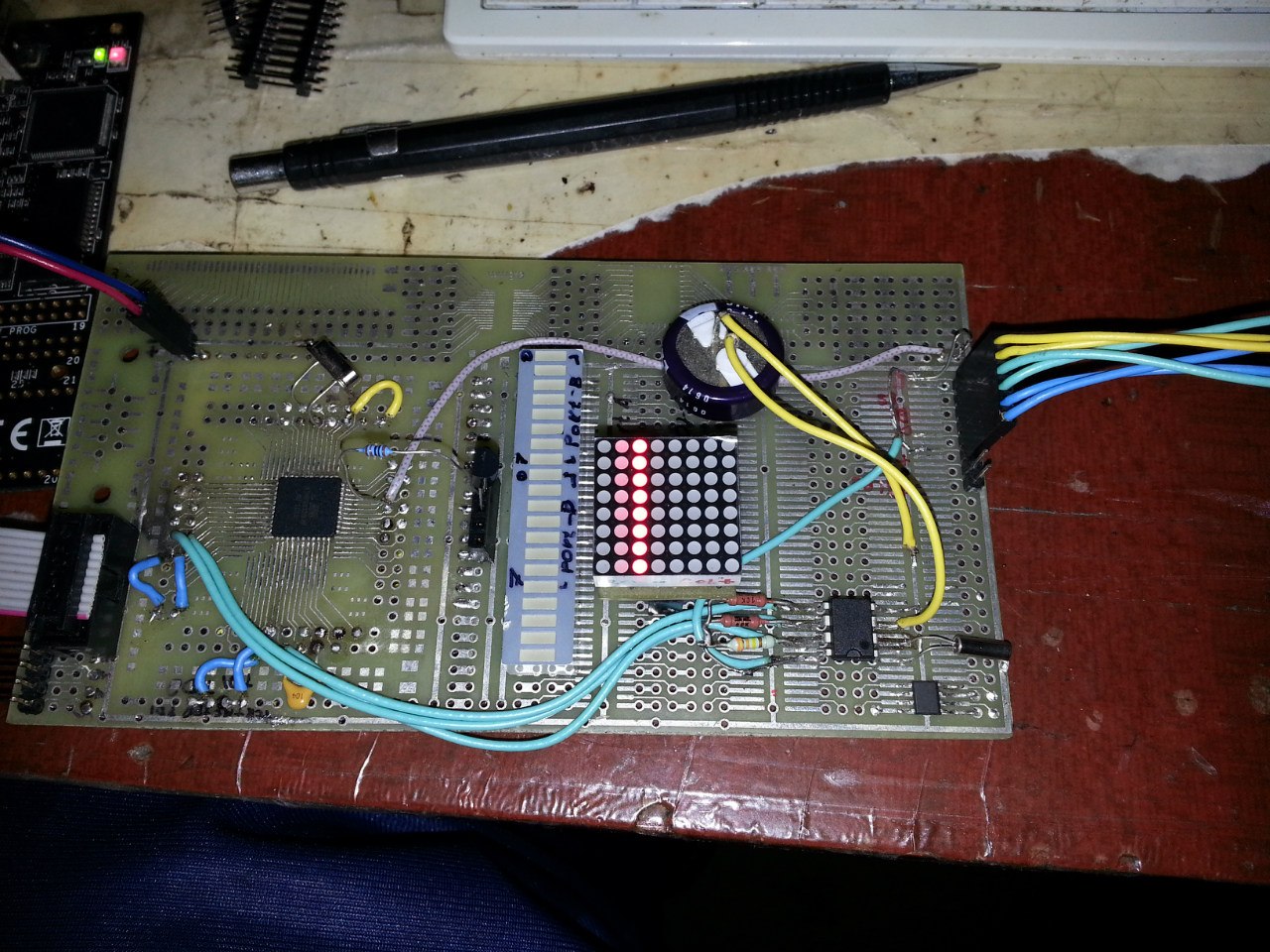
- MCeg ATMega1284p on the debug board (looks rather messy, but it was shared for itself).
- Piezo emitter
- Thermometer DS18B20, a library rewritten from scratch. The basic minimum of functions: “Read byte”, “Start conversion”, “Read Scratchpad”.
- RTC DS1307
The thermometer library will be rewritten to optimize and eliminate delays in the operation of the MCU during conversion. At the moment, the temperature conversion makes the MCU freeze at ~ 750ms, which creates very unpleasant pauses when working with the network, as well as sound.
A few photos
ENC28J60:
Step-Down DC-DC Converter (LM2596):

The modules themselves:
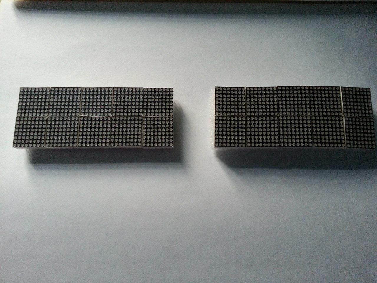
Module assembly + rear pinout and partially visible adapter circuit.

Link to the LED modules themselves (not the store), as well as an example of managing them here .
Debug board + module in it. It shines MUCH brighter than in the photo. Powered by 5V without limiting resistors. In vain, in vain, in vain ... but it works! The second column is powered through a pull-up resistor holding 1-Wire for the DS18B20 (to the left):
Step-Down DC-DC Converter (LM2596):
The modules themselves:
Module assembly + rear pinout and partially visible adapter circuit.
Link to the LED modules themselves (not the store), as well as an example of managing them here .
Debug board + module in it. It shines MUCH brighter than in the photo. Powered by 5V without limiting resistors. In vain, in vain, in vain ... but it works! The second column is powered through a pull-up resistor holding 1-Wire for the DS18B20 (to the left):
Why not:
- Added libraries
- DMA a very sorry.
- Sign generator. (Done)
- Adapters for LED modules (the wiring of the modules is simply terrible, but it will be more convenient for the panel to assemble them when the row is on one side and the columns are on the other.
/ It was not commercially profitable to order adapters. The price at the plant was crushed at a rate of 4000 (excluding VAT) for 40 pieces. With VAT we get almost 5k wooden. We'll have to hone our skills with the mini-drill and LUT. /
The matrix of characters is planned 6x8, without font optimizations.
//A
{
0b00000000,
0b00100000,
0b01010000,
0b01010000,
0b10001000,
0b11111000,
0b10001000,
0b00000000,
}
Moreover, only 6 high-order bits will be displayed, the remaining 2 will be skipped.
There will be no pseudographics yet.
The output of the picture from the "network" is probably, too. But to describe the graphic buffer for long, you can make animations directly from the server.
There was an idea to buy a Raspberry PI and write a script on top of it ... but it’s not sports. There, the ARM-11 system, 512MB RAM, Linux ... yes, you can raise the monitoring server there! .. but the real time in any * nix system is soft, and hard display is required to display.
Of course, you could make RPI + any simpler controller such as ATMega48 (yes, it is also available), with SPI / UART exchange and peripherals on top of the controller itself, but this is also not sports.
The goal of the project was set for itself “To keep within a small budget and assemble an alert device”, which is why it is done that way. Almost healthy sports interest.
To be continued.