Modification of the ventilator or ventilation control from the carbon dioxide sensor
The level of carbon dioxide (CO2) is one of the important indicators of indoor air quality. Also, its level is very convenient to use for ventilation control.
In the article I will tell about the refinement of the ventilator and the remote control of fans through microcontrollers and a CO2 sensor.
Also, if desired, after a little refinement, the same scheme can be applied to control the supply and exhaust system.
The average apartment is usually designed for natural ventilation. This is when air enters through cracks in the windows and exits through an exhaust hole somewhere in the area of the kitchen, toilet, etc.
As a rule, there are no gaps in an apartment with plastic windows installed, and in order for the ventilation to work, you have to open the windows or windows, which improves the air situation with a normally working hood.
But in this way we add street noise.
You can get fresh air in the room without noise by installing:
- Supply system
- Ventilators supplying air from the street through a hole in the main wall
The first option solves all problems, but it is expensive and requires space for equipment, ventilation ducts.
The second option is simpler, but since the ventilation unit itself is of a limited size, the noise will depend on its operating mode.
Here is this option and consider.
Here is a table of carbon dioxide levels and their health effects in order to know what to strive for:
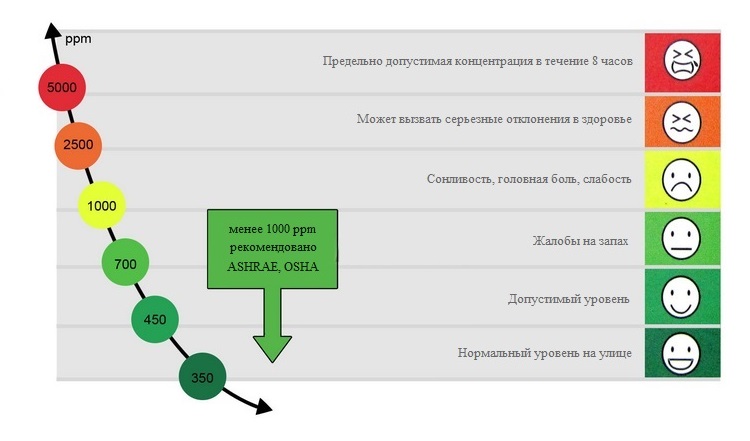
Thus, we will consider a CO2 level of 450-1000 ppm optimal for the room.
I’ll tell you about my experience that with the windows and doors closed, turned on at the minimum of the ventilator and when there are two people in the room, by the morning it turns out somewhere around 1200-1500 ppm, which is a bit much.
Work algorithm
The algorithm used to control ventilation performance is quite simple, but you can complicate it if you wish:
- It takes the average CO2 level received from the sensor over time.
- There are 6 threshold values and depending on this, the fan speed is selected, which is transmitted over the air to the microcontrollers that control the fans.
- When lowering the CO2 level, there is a certain threshold, only after which a decrease in speed occurs.
- At night, maximum fan speed is limited to reduce noise.
- By commands from the remote control, you can increase or decrease the overall ventilation performance, and specifically each fan.
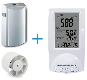
The carbon monoxide MIC 98130 was used as a carbon dioxide sensor.
Air is supplied through the Aeropac 90A.
The hood is reinforced with a SystemAir IF 150 duct fan.
Atmel AVR ATtiny44A microcontrollers are used for control.
Data is transferred from the controller connected to the CO2 monitor to the controllers that control the fans using the modules on the NRF24L01 + transceiver.
Setting the operating mode and setting is possible using any IR remote control, either a magnet or a button.
Refinement of the CO2 monitor
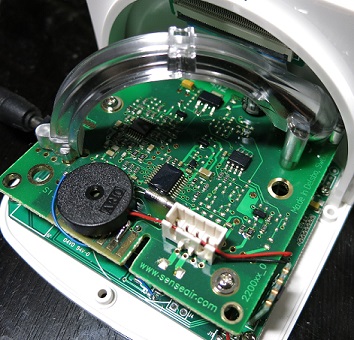
The CO2 monitor ordered on ebay, as it turned out, has a SenseAir K22 infrared gas analyzer with fairly good accuracy.
And most importantly - it has a special output with a CO2 level (in the picture there is a white connector with four contacts).
On this connector, from left to right:
- power supply + 9V
- common
- CO2 output in PWM from 350 to 2000 ppm
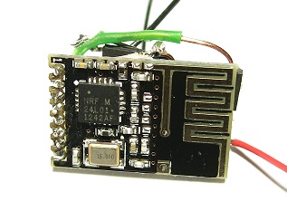
There is not much free space inside, therefore, a mini-board with a NRF24L01 + transceiver was used for refinement and a microcontroller in a SOP14 package with a harness was sealed on it. Before sealing, the DWEN fuse was turned on for programming and debugging using the debugWIRE protocol.
There is one remark on radio modules - the transmission range is not large enough.

Especially if there are walls, doors between the transmitter and receiver. So it is better to choose modules with an external antenna or try to keep as few obstacles as possible between the transmitter and the receiver.
There is a nRF24L01 + compatible Chinese chip with increased transmit power - SI24R01.
Modules with it are usually cheaper, so it is better to take with it.
True, I did not find sane mini-modules with this chip, and the project also uses modules with the native nRF24L01 + chip.
To enable increased transmit power, SI24R01 uses bit 0 of the RF_SETUP register.
A divider is assembled on resistors R1, R2 to reduce the voltage received from the sensor.
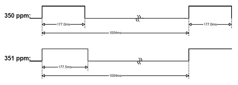
The value of CO2 is obtained by calculating the time between the change of level on the foot of the controller. Time is taken from a 16-bit timer counter.
To conduct less calculations, the microcontroller operates at a frequency of 8.192 MHz, and the timer divider is set to 1024.
Thus, the timer counter TCNT1 is incremented every 0.125ms.
It turns out in order to calculate the CO2 level - you need to divide the timer counter by 4 and subtract 4. The
PWM signal at the sensor output:
Scheme: LDR1 photoresistor is used to determine the threshold of darkness, the button is used for initial memorization of IR remote control commands. The LED informs about transmission errors, and is also used for tuning. To control and configure, I decided to use a conventional IR remote control, the commands of which must first be registered in the microcontroller. Entering programming mode - press and hold the button for more than 3 seconds. Then, in order, irradiate the IR receiver by pressing the buttons on the remote control. IR commands:

- up,
- way down,
- the choice
- setting the speed adjustment of each fan.
In normal mode, the up and down commands increase or decrease the speed of all fans by one step.
The command "choice" - reset.
Using command 4, one enters the speed offset setting mode of each fan. First, the fan number is selected, then, after selection, the offset is entered. The LED in this mode blinks the current selection.
Commands are identified by the microcontroller as follows:
- using timer 0 we get the time from the previous signal edge (interrupt PCINT1)
- if this is the first impulse, then we check its duration in order to immediately eliminate false triggering
- if there was a change in duration by 1.5 times compared to the previous value, then add 1 to the bitmap, otherwise 0.
- calculate the hash (2 bytes) of the bitmap and use it to identify the command
A simple hash function is used to reduce the load on the controller,
with the formula: hash = hash * 17 + x
		if(IRSignalTimer > IRSignalTimerLast) // bit = a / b > 1.5
			bit = (uint8_t)(IRSignalTimer - IRSignalTimerLast) > IRSignalTimerLast / 2;
		else
			bit = (uint8_t)(IRSignalTimerLast - IRSignalTimer) > IRSignalTimer / 2;
		IRReadedByte = (IRReadedByte << 1) | bit;
		if(++IRArrayBit > 7) {
			IRArrayBit = 0;
			IRHash = ((IRHash << 4) + IRHash) + IRReadedByte; // * 17
			IRReadedByte = 0;
		}
Many articles have been written on working with radio modules NRF24L01, so I won’t go into this topic.
I can only say that they are configured to work at a speed of 1Mbps, CRC is used, and each transmission must be confirmed by an ACK packet.
The hardware USI interface is used for communication between the controller and the module.
IRQ output is not used, the verification of the confirmation of the transmission of the packet goes in a loop in the function NRF24_Transmit.
It is transmitted to each fan - CO2 level, fan speed and a sign of night.
In the current project, the controllers controlling the fans so far use only speed.
Refining ventilator
I have installed ventilators Aeropac 90A company SIEGENIA-AUBI - this is a fairly ancient model.
It has been working for more than one year and, as practice has shown, the thing is generally useful.
He drives air through an 80 mm hole in the wall and has a carbon filter.
Soundproofing from sounds from the street is very good.
Inside installed centrifugal fan Ebmpapst R2E133-BH96-19.
With all the noise of the fan itself, after so many years of operation, things are not going smoothly. At low revs, a low-frequency hum can occur, and at high revs, some howl.
Moreover, this is manifested individually. One fan buzzes more at low speeds, the other whistles at high.
Solved this problem by speed limitation.
In the ventilator, a very interesting scheme for adjusting engine speed is implemented - from low to medium speed smoothly, and then the maximum speed starts immediately.
If at minimum and medium speeds it works quite quietly, then at maximum speed it is not comfortable to be in the room.
In the new model - Aeropac SN, despite the digital step-by-step adjustment, the principle of speed control remains the same - from 1 to 6 speeds, the speed is regulated somewhere to the middle, and then immediately the maximum.
In the diagram, the ventilator electronic unit is surrounded by a dashed line: The refinement consists in cutting the track leading from the middle terminal of the variable resistor RV1 to the resistors R6 and R7. Optocouplers U2 and U3 are connected to the gap, which will control the fan speed.
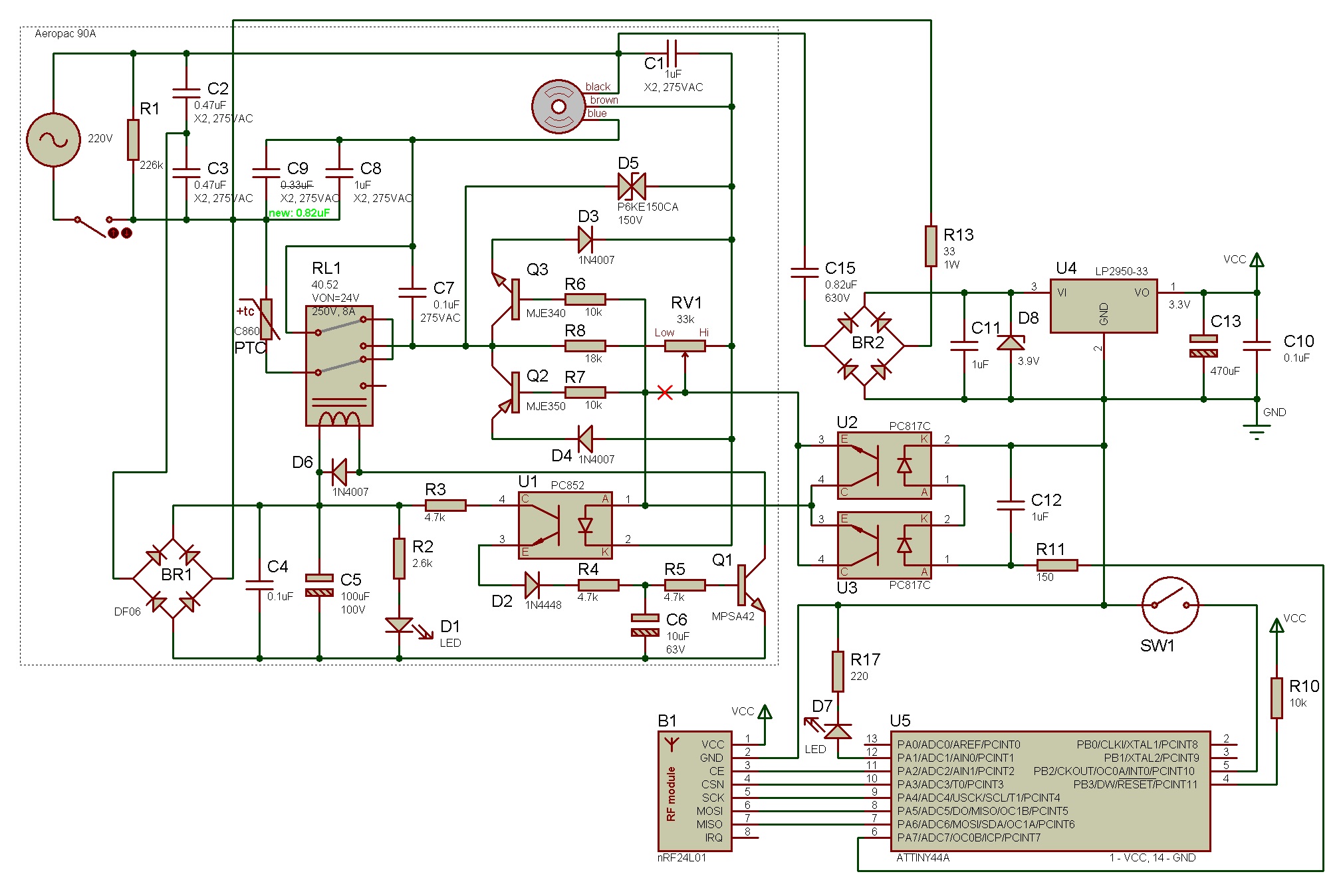
The PWM control signal to the optocouplers is supplied by the microcontroller through an integrating RC circuit.
The LED in the optocoupler starts to conduct current only from a certain voltage, so the program has a setting for the minimum value of the PWM signal.
The variable resistor remains, and they, if desired, can limit the maximum speed.
If the performance at medium speed is not enough, then it can be increased by replacing the capacitor C9 with a capacitor of a larger capacity. The board prudently has openings for two sizes of capacitors - with a distance of 27.5mm and 22mm between the terminals.

There is enough space inside the ventilator - more than one board will fit.
The only problem may arise with the radio modules. The case is double and made of thick plastic.
With the radio module on the native chip nRF24L01 + there was no connection with the next room.
I got it out like this - I soldered a single-core copper wire to the built-in antenna, brought it out through the hole for the LED and placed the end under the twist of the variable resistor. With the coordination of the antenna did not bother.
The connection has appeared.
A reed switch (SW1) is used instead of a button to configure, so as not to spoil the appearance and not violate the sound insulation.
The magnet from the hard drive is enough.
Cooker hood
The incoming air should eventually go somewhere. A natural hood, even if it somehow copes in the winter, then in the summer it will most likely not be enough.
In my case, I used a SystemAir IF 150 duct fan with a single-phase motor. He has an external diameter of 15 cm. The
adjustment of his speed is stepwise and is done on capacitors. Opto-triacs shunt capacitors, thus changing the voltage supplied to the fan motor.
With two capacitors, 4 speeds are obtained.
Scheme: Since the hood is installed in the kitchen, I decided at the same time to make additional fan control from the remote control. So that if something serious is cooked on the stove, by pressing a single button turn on the hood to the maximum.
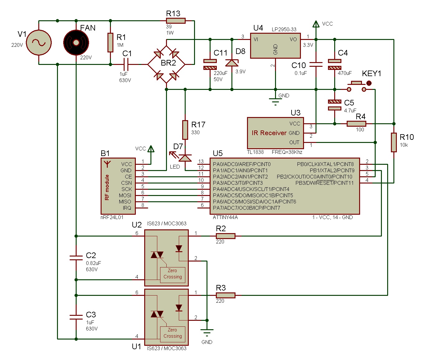

The speed received over the air is ignored.
The fan control program is universal and, depending on the settings in non-volatile memory, can control fans using PWM or in discrete mode.
Whether the IR receiver is connected to the controller is also specified in the EEPROM.
The program includes the ability to relay the received packet further - to another fan.
Thus, for example, the distance between the CO2 sensor and the exhaust fan can be increased.
C source (for Atmel Studio 6.1): github.com/vad7/WirelessCO2
Mirror: vad-7.blogspot.com/2013/12/blog-post.html