Connecting an Accelerometer to a Raspberry Pi Using the Pi4J Library
Foreword
Hello, Habr! Just recently, they took me into a robotics club. Of course, I gladly agreed, this is a new experience and all that ... Especially since I'm just a freshman. My teacher, explaining to me the general concept, suggested to work with Raspberry Pi. It was necessary to figure out how to work with it, install the JDK on it and write a program that would display indications from a 3-axis accelerometer. Taking everything I needed, I went home to sort it out. When I finished (it took about a week), I decided to write a guide addressed to the same as I, in order to collect everything that I dig in one place. Well, enjoy your reading!
First thing
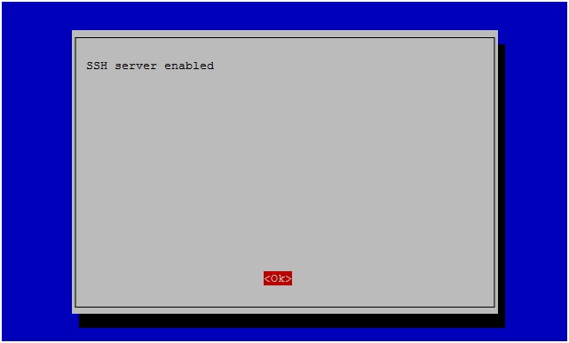
First of all, you need to access our device. We will connect using the SSH protocol. By default, the SSH server is disabled, and to enable it, connect Raspberry to a monitor or TV, connect a keyboard and mouse. Of course, you can simply scan the network environment, identify our device and connect using the IP found, but still I recommend doing it according to my version. After loading the terminal launches and enter the command sudo raspi-config . In the menu that opens, go to advanced options-> SSH and select Enable. After these manipulations, the following window should appear:
Excellent! Now we can connect to our “raspberry” at any time. Let's write the network settings right away. The file we need is in the /etc/network/ directory. We go there using the commandcd / etc / network . Next, open the desired file by entering sudo nano interfaces . Here we write in the corresponding lines our data, thereby we set the static IP address. You should get something like the following:
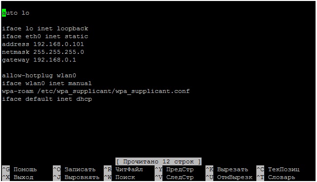
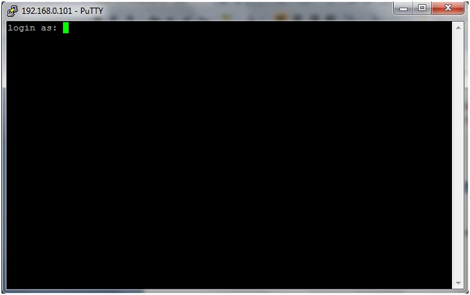
After press CTRL + X, Y, Enter. It is at this address that we will connect. Next, download the SSH client - PuTTY . Running the program, you will see the following window:
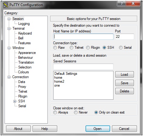
Here in the Host Name field we write the same ip that we registered in interfaces. Here you can save the settings by writing a name in the Save Session field and clicking Save. Click Open. As soon as PuTTY connects to the SSH server, a window will open and a credential prompt will appear (by default, user: pi, password: raspberry):
Do not be alarmed that when entering you do not see the password; on Linux-like systems, the password is simply not visible, although input does occur. Press Enter. If everything went well, you will see the following window:
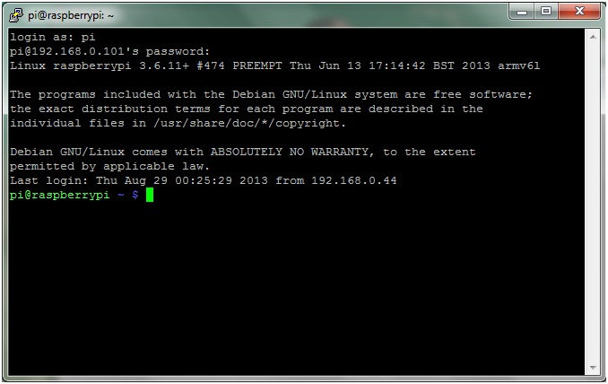
In this console, you can execute any commands and they will be executed on the device itself. Is it convenient?
Install JDK
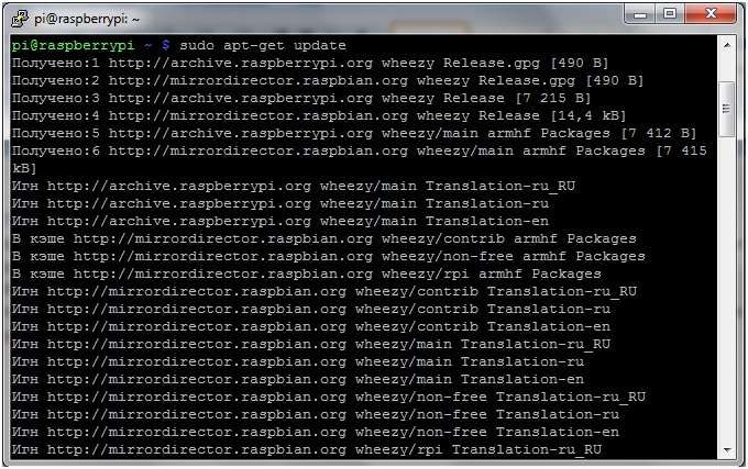
Everything is pretty simple here. We update the list of packages by typing sudo apt-get update in the terminal .
We will update the sudo apt-get upgrade system itself .

All this may take quite a while (I had this update taking about 30 minutes), so stock up on tea. Glory to the great power that the JDK package was added to the package lists, and we did not have to dance with a tambourine. To install the package, simply enter sudo apt-get install openjdk-7-jdk .
To test the performance, we introduce java -version. You should see something like the following:

PS On some machines, a problem may occur due to the system not finding the JDK package. It occurs due to the incompatibility of the Debian “wheezy” kernel with java. Try reinstalling the OS on the Debian “wheezy” Soft-float, optimized for working with java. In any case, everything fell on my “raspberry” the first time. Here is my version:

I2c vs Raspberry PI
So now the fun begins! To get started, let's figure out what it all is? The great and mighty Wikipedia says:
I²C (Russian ai-tu-si / and-two-tse / and-two-si) is a serial data bus for communication of integrated circuits, using two bi-directional communication lines (SDA and SCL). Used to connect low-speed peripheral components to the motherboard, embedded systems, and mobile phones. The name is an abbreviation of the words Inter-Integrated Circuit.
In my work, I use this LSM303DLM device , in the future all examples will be shown on it. Below I drew a connection diagram:
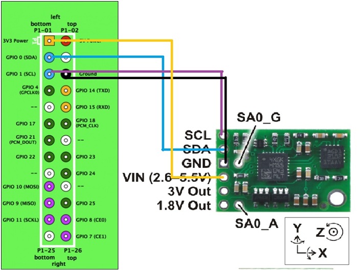
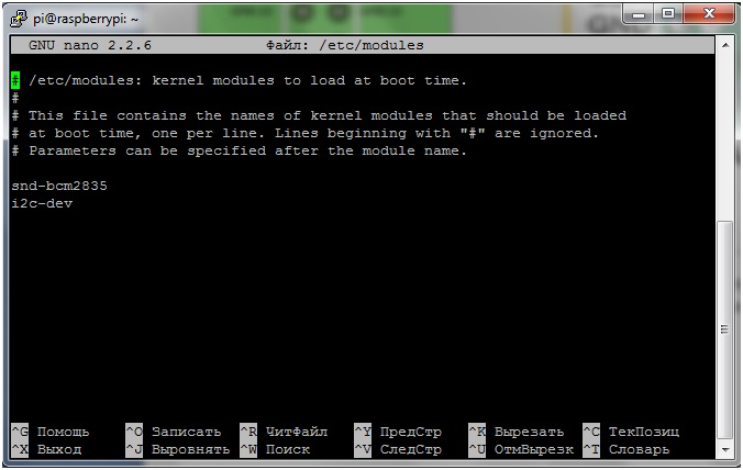
It is quite simple, and I think it requires no explanation. Let's continue. Oh yes, let's immediately add a couple of lines to the file responsible for the startup of the modules. We write sudo nano / etc / modules on the command line and add it there:
i2c-bcm2708
i2c-dev
Now we install the i2c-tools package. In the terminal we write: sudo apt-get install python-smbus and sudo apt-get install i2c-tools .
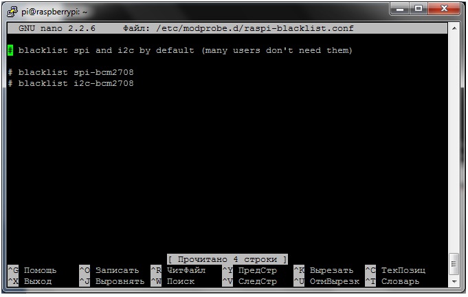
Editing the blacklist. To do this, write sudo nano /etc/modprobe.d/raspi-blacklist.conf. Add lines:
blacklist spi-bcm2708
blacklist i2c-bcm2708
All. We have done all the essentials for working with I2C, now let's check if we see our device. The i2cdetect utility includes the i2cdetect command, which we need. But first, check that the drivers are successfully installed. We write in the terminal i2cdetect –l . If we see the following:

Then everything is fine, you can move on. Now we write i2cdetect –y 1 ( i2cdetect –y 0 ). We see the address lattice:
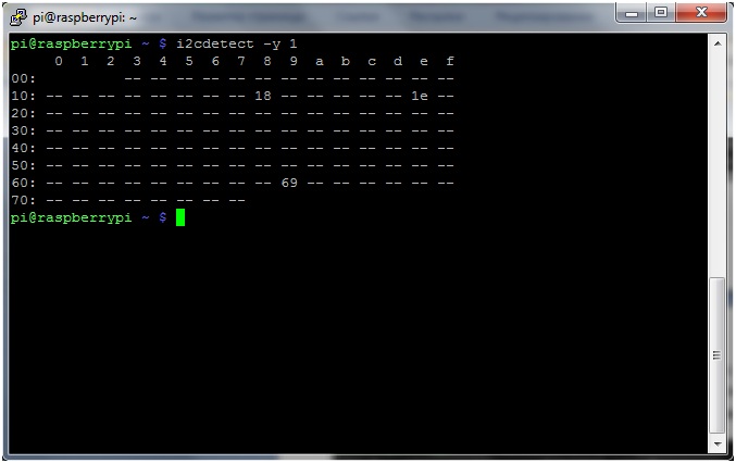
In my case, the address of the accelerometer is 0x18 (you can find out, for example, in the documentation). Now let's talk about PI4J.
Wow wow wow paleh ...
To work with I2C using JAVA tools, you need to download and install an additional PI4J library. Read about it here . Download by writing wget pi4j.googlecode.com/files/pi4j-0.0.5.deb in the terminal . Install by writing: sudo dpkg -i pi4j-0.0.5.deb . Check the installed files:

Now to compile the program we write:
javac -classpath.: Classes: / opt / pi4j / lib / '*' (name)
To run:
sudo java -classpath.: Classes: / opt / pi4j / lib / '* '(name)
Of all the packages, 3 will come in handy:
import com.pi4j.io.i2c.I2CBus;
import com.pi4j.io.i2c.I2CDevice;
import com.pi4j.io.i2c.I2CFactory;
We create references to objects of classes I2CDevice and I2CBus.
import java.io.IOException;
import com.pi4j.io.i2c.I2CBus;
import com.pi4j.io.i2c.I2CDevice;
import com.pi4j.io.i2c.I2CFactory;
public class accelerometrOne {
	static I2CDevice device;
	static I2CBus bus;
	static byte[] accel;
    public static void main(String[] args) throws IOException {
        System.out.println("Starting sensors reading:");
        try {
           bus = I2CFactory.getInstance(I2CBus.BUS_1);
           System.out.println("Connected to bus OK!");
           device = bus.getDevice(0x18);
           System.out.println("Connected to device OK!");
        } catch (IOException e) {
           System.out.println(e.getMessage());
        }
    }
}
Let's analyze the code. By line bus = I2CFactory.getInstance (I2CBus.BUS_1); we connect to our bus, and using device = bus.getDevice (0x18); We are connecting to our device.
Now you need to calibrate the accelerometer. We climb into the documentation .
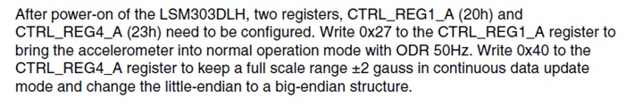
Who has absolutely everything bad with English. In my free translation: “After turning on the LSM303DLH, you need to configure the device using 2 registers CTRL_REG1_A (20h) and CTRL_REG2_A (23h). To do this, write 0x27 in the first register for normal operation with 50Hz ODR.
We write 0 * 40 in the second register in order to preserve the full range of measurements + - 2 gauss in the continuous updating of the database and change the order of bytes from low to high by an order of magnitude from high to low. ”
To write data to the device, we use the write method from the I2CDevice class . Let's add the program:
import java.io.IOException;
import com.pi4j.io.i2c.I2CBus;
import com.pi4j.io.i2c.I2CDevice;
import com.pi4j.io.i2c.I2CFactory;
public class accelerometrOne {
	static I2CDevice device;
	static I2CBus bus;
	static byte[] accel;
    public static void main(String[] args) throws IOException {
        System.out.println("Starting sensors reading:");
        try {
           bus = I2CFactory.getInstance(I2CBus.BUS_1);
           System.out.println("Connected to bus OK!");
           device = bus.getDevice(0x18);
           System.out.println("Connected to device OK!");
           device.write(0x20, (byte) 0x27);
           device.write(0x23, (byte) 0x40);
           System.out.println("Configuring sensors OK!");
        } catch (IOException e) {
           System.out.println(e.getMessage());
        }
    }
Excellent!!! It remains to read the data from the device. We climb into the documentation again and find out that the data is given out by 2 bytes per axis:
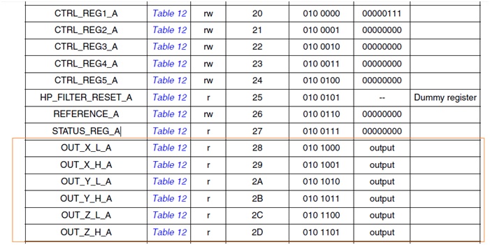
Well, that’s it. We write the received bytes into an array and display the data on the screen:
import java.io.IOException;
import com.pi4j.io.i2c.I2CBus;
import com.pi4j.io.i2c.I2CDevice;
import com.pi4j.io.i2c.I2CFactory;
public class accelerometrOne {
	static I2CDevice device;
	static I2CBus bus;
	static byte[] accel;
    public static void main(String[] args) throws IOException {
        System.out.println("Starting sensors reading:");
        try {
           bus = I2CFactory.getInstance(I2CBus.BUS_1);
           System.out.println("Connected to bus OK!");
           device = bus.getDevice(0x18);
           System.out.println("Connected to device OK!");
           device.write(0x20, (byte) 0x27);
           device.write(0x23, (byte) 0x40);
           System.out.println("Configuring sensors OK!");
           readingsensors();
        } catch (IOException e) {
           System.out.println(e.getMessage());
        }
    }
    private static void readingsensors() throws IOException {
		while (true) {
			accel = new byte[6];
			accel[0] = (byte) device.read(0x28);
			accel[1] = (byte) device.read(0x29);
			accel[2] = (byte) device.read(0x2a);
			accel[3] = (byte) device.read(0x2b);
			accel[4] = (byte) device.read(0x2c);
			accel[5] = (byte) device.read(0x2d);
			int accelx = asint(accel[0]) * 256 + asint(accel[1]);
			int accely = asint(accel[2]) * 256 + asint(accel[3]);
			int accelz = asint(accel[4]) * 256 + asint(accel[5]);
			System.out.println("accelx: " + accelx + ", accely: " + accely
					+ ", accelz: " + accelz);
		}
	}
    private static int asint(byte b) {
        int i = b;
        if (i < 0) {
            i = i + 256;
        }
        return i;
    }
}
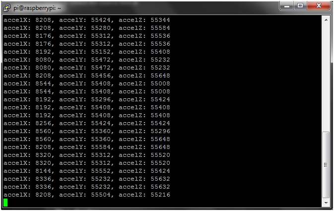
As a result, after launch, we will see something like the following: