Channel consolidation, or the solution of one telecommunication problem
I am an employee of one small operator. I have never written an article, but there was one problem that prompted me to write this review.
We faced the problem that in one of the areas in which we deployed a channel for presenting services to our clients, we had a client who needed to connect a newly installed PBX, and certainly connect via E1 stream. Between our central node and the remote point of presence of the client, only Gigabit Ethernet was transmitted through the rented fiber, so we needed to additionally transfer the E1 channel. The situation was complicated by the large attenuation in the optical fiber between the communication nodes, and therefore long-range SFP modules of 30 dB (120 km) were installed in our switches to operate on a single leased fiber. After analyzing possible solutions to the problem, several possible approaches were proposed:
1) Rent one more optical fiber and install an E1 optical modem on it;
2) Seal the optical line between the communication nodes of the CWDM system.
3) Install a pseudowire transmission device (TDM over IP, en.wikipedia.org/wiki/TDMoIP ) on a working data network and convert E1 to Ethernet, then transfer between the objects in converted form, and perform the reverse conversion on the central node;
4) Find a device that combines Gigabit Ethernet transmission with E1 transmission and supports operation at high attenuation on the optical line.
The first solution was immediately discarded, as it required a periodic subscription fee for additional fiber. The second option seemed quite suitable, but it required the installation of several additional components: a CWDM multiplexer and a media converter (multiplexer) with an E1 port and an uplink port in the form of an SFP for connecting to a CWDM multiplexer. If the E1 modem had a fixed E1 port, it would be necessary to additionally install an active wavelength converter to connect the modem to CWDM to the system. The decision was somewhat cumbersome, and this was also discarded.
The third solution turned out to be quite real, however, the client required the conclusion of an agreement with one mandatory clause “E1 G.703 stream should be transmitted without conversion and structural changes, as well as without the use of pseudowire data transfer technologies”. Therefore, they also decided to refuse this decision. The last option remained.
The requirements for the device were formulated: the presence of a Gigabit Ethernet port, an E1 port (at least 2x for possible expansion), an integrated long-range optical port, or an SFP port for installing optical modules. The last criterion was the support of long-range optical modules, since in my experience not all devices support them.
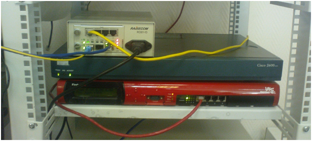
After a short search on the Internet, we found the right device and took it for a test in our laboratory to solve our problem. We received the appropriate equipment: RCMS2912-4 / 8T1E1GE 2 multiplexer. ( http://www.raisecom.su/equipment/e1ethopt/multiservpdh/rcms2912/ ), chassis for installing multiplexers - RC001-1D-WP 2 pcs. ( http://www.raisecom.su/equipment/chassis/rc0011d/ ). In a complete set to devices also there were disks with instructions in English.


The RCMS2912 multiplexer on board had a Gigabit Ethernet copper port, four E1 ports, and two SFP ports for installing optical modules. The front panel also displays several indicators responsible for displaying alarms on the E1 ports, the status of the Ethernet port, as well as the status of the optical ports.
One of the first doubts that we then had was whether the device would work with existing long-range SFP modules that were installed in a working switch on the communication center. Since we had the same spare SFPs in reserve, we managed to conduct the test “on the table” without installing the equipment on the network. The circuit was assembled.
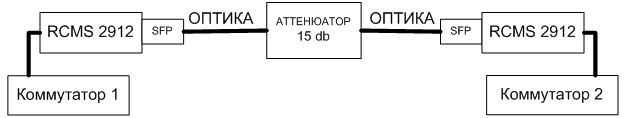
Packets were sent from switch 1 to switch 2 using the ping utility. The test was successful, our SFPs began to work safely in the new equipment.
ping 172.10.2.165 count 100 waittime 1
Type CTRL + C to abort.
Sending 100, 8-byte ICMP Echos to 172.10.2.165, timeout is 1 seconds:
!!!
- PING Statistics ----
100 packets transmitted,
100 packets received, Success rate is 100 percent (100/100)
round-trip (ms) min / avg / max = 0/0/0
Next, it was necessary to check the operation of the devices for E1 transmission . Unfortunately, at that time in our “mini-laboratory" there was no E1 tester, we used two CISCO 2610 routers to check E1. The following circuit was assembled.

The only difficulty in preparing for the test was preparing the E1 cable for connecting the CISCO 2610 and RCMS-2912. To do this, I had to raise the pinout of the CISCO module on the Internet + watch the pinout of the Raisecom multiplexer. After connecting devices according to the above scheme, the channel went up, and packets began to successfully pass between routers. The test has been passed.
It was decided to conduct a test on the bandwidth of the Gigabit Ethernet channel. Only 3 computers with Gigabit Ethernet network cards were available. As the software used iperf. Pre-assembled circuit

between two PCs. The result was
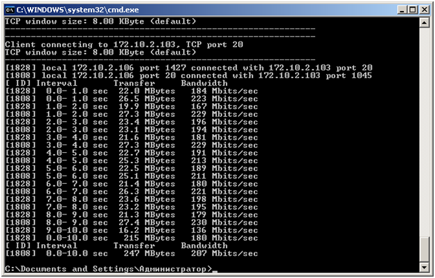
Then the circuit was assembled.

And the result is obtained

Thus, the device coped with the load quite well and the test was subsequently repeated on a working channel at a speed of ~ 450 Mbit / s.
One of the additional features of the device was support for SFP port redundancy. This function allows the device to switch to the second optical port if the link on the first optical port drops.
It was decided to check the operation of this function as well. We did not have an additional pair of long-range modules, and 20 km SFP was used and the circuit was assembled.

For the test - PC_A turned on iperf in server mode, on PC_B turned on iperf test over UDP with the following settings.
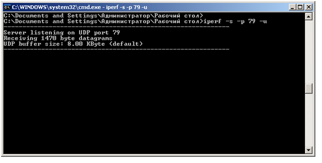
On PC_B, iperf ( http://sourceforge.net/projects/iperf/ ) was launched in client mode to run the test using the UDP protocol.
The goal was to determine whether packet loss would occur when switching between two optical channels. In turn, we pulled out and installed optical patch cords in place. The result was as follows:
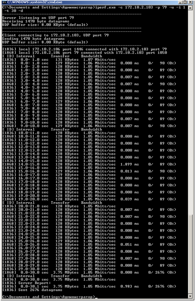
The test showed that during the test no UDP packets were lost. The device successfully coped with the task.
After all the tests, it was decided to install the device on a working network. A 48-hour test showed that the device worked without failures, after which we connected the client.
This solution turned out to be quite profitable - about 60,000 rubles, when compared with other options for solving the problem.
We faced the problem that in one of the areas in which we deployed a channel for presenting services to our clients, we had a client who needed to connect a newly installed PBX, and certainly connect via E1 stream. Between our central node and the remote point of presence of the client, only Gigabit Ethernet was transmitted through the rented fiber, so we needed to additionally transfer the E1 channel. The situation was complicated by the large attenuation in the optical fiber between the communication nodes, and therefore long-range SFP modules of 30 dB (120 km) were installed in our switches to operate on a single leased fiber. After analyzing possible solutions to the problem, several possible approaches were proposed:
1) Rent one more optical fiber and install an E1 optical modem on it;
2) Seal the optical line between the communication nodes of the CWDM system.
3) Install a pseudowire transmission device (TDM over IP, en.wikipedia.org/wiki/TDMoIP ) on a working data network and convert E1 to Ethernet, then transfer between the objects in converted form, and perform the reverse conversion on the central node;
4) Find a device that combines Gigabit Ethernet transmission with E1 transmission and supports operation at high attenuation on the optical line.
The first solution was immediately discarded, as it required a periodic subscription fee for additional fiber. The second option seemed quite suitable, but it required the installation of several additional components: a CWDM multiplexer and a media converter (multiplexer) with an E1 port and an uplink port in the form of an SFP for connecting to a CWDM multiplexer. If the E1 modem had a fixed E1 port, it would be necessary to additionally install an active wavelength converter to connect the modem to CWDM to the system. The decision was somewhat cumbersome, and this was also discarded.
The third solution turned out to be quite real, however, the client required the conclusion of an agreement with one mandatory clause “E1 G.703 stream should be transmitted without conversion and structural changes, as well as without the use of pseudowire data transfer technologies”. Therefore, they also decided to refuse this decision. The last option remained.
The requirements for the device were formulated: the presence of a Gigabit Ethernet port, an E1 port (at least 2x for possible expansion), an integrated long-range optical port, or an SFP port for installing optical modules. The last criterion was the support of long-range optical modules, since in my experience not all devices support them.
After a short search on the Internet, we found the right device and took it for a test in our laboratory to solve our problem. We received the appropriate equipment: RCMS2912-4 / 8T1E1GE 2 multiplexer. ( http://www.raisecom.su/equipment/e1ethopt/multiservpdh/rcms2912/ ), chassis for installing multiplexers - RC001-1D-WP 2 pcs. ( http://www.raisecom.su/equipment/chassis/rc0011d/ ). In a complete set to devices also there were disks with instructions in English.
The RCMS2912 multiplexer on board had a Gigabit Ethernet copper port, four E1 ports, and two SFP ports for installing optical modules. The front panel also displays several indicators responsible for displaying alarms on the E1 ports, the status of the Ethernet port, as well as the status of the optical ports.
One of the first doubts that we then had was whether the device would work with existing long-range SFP modules that were installed in a working switch on the communication center. Since we had the same spare SFPs in reserve, we managed to conduct the test “on the table” without installing the equipment on the network. The circuit was assembled.
Packets were sent from switch 1 to switch 2 using the ping utility. The test was successful, our SFPs began to work safely in the new equipment.
ping 172.10.2.165 count 100 waittime 1
Type CTRL + C to abort.
Sending 100, 8-byte ICMP Echos to 172.10.2.165, timeout is 1 seconds:
!!!
- PING Statistics ----
100 packets transmitted,
100 packets received, Success rate is 100 percent (100/100)
round-trip (ms) min / avg / max = 0/0/0
Next, it was necessary to check the operation of the devices for E1 transmission . Unfortunately, at that time in our “mini-laboratory" there was no E1 tester, we used two CISCO 2610 routers to check E1. The following circuit was assembled.
The only difficulty in preparing for the test was preparing the E1 cable for connecting the CISCO 2610 and RCMS-2912. To do this, I had to raise the pinout of the CISCO module on the Internet + watch the pinout of the Raisecom multiplexer. After connecting devices according to the above scheme, the channel went up, and packets began to successfully pass between routers. The test has been passed.
It was decided to conduct a test on the bandwidth of the Gigabit Ethernet channel. Only 3 computers with Gigabit Ethernet network cards were available. As the software used iperf. Pre-assembled circuit
between two PCs. The result was
Then the circuit was assembled.
And the result is obtained
Thus, the device coped with the load quite well and the test was subsequently repeated on a working channel at a speed of ~ 450 Mbit / s.
One of the additional features of the device was support for SFP port redundancy. This function allows the device to switch to the second optical port if the link on the first optical port drops.
It was decided to check the operation of this function as well. We did not have an additional pair of long-range modules, and 20 km SFP was used and the circuit was assembled.
For the test - PC_A turned on iperf in server mode, on PC_B turned on iperf test over UDP with the following settings.
On PC_B, iperf ( http://sourceforge.net/projects/iperf/ ) was launched in client mode to run the test using the UDP protocol.
The goal was to determine whether packet loss would occur when switching between two optical channels. In turn, we pulled out and installed optical patch cords in place. The result was as follows:
The test showed that during the test no UDP packets were lost. The device successfully coped with the task.
After all the tests, it was decided to install the device on a working network. A 48-hour test showed that the device worked without failures, after which we connected the client.
This solution turned out to be quite profitable - about 60,000 rubles, when compared with other options for solving the problem.