MPLS and VPLS on Mikrotik
On the one hand, the desire is somewhat strange - the organization of a "serious" MPLS / VPLS on cheap hardware like Mikrotik. On the other hand, for 70 bucks (1500-2000r) for the younger RB / 750 (GL) model, we get a PE / CE device that can (among other things) L2VPN / L3VPN on top of the MPLS environment and can pump about 70 megabits of duplex through itself (on large packages).
Mikrotik RouterOS can both MPLS (L3VPN, Traffic Engeneering), and L2VPN (l2circuit aka VPWS, VPLS), which covers almost all possible tasks (given the performance of iron, of course).
Interesting? I ask for a cut!
For starters, a bit of theory.
MPLS ( multiprotocol label switching) Is a label-based routing mechanism. Each packet passing through the MPLS network, regardless of the type of packet, is assigned a specific label based on which a routing decision is made. It is important to note that the content is not studied, i.e. inside MPLS, you can drive absolutely any L2 / L3 traffic (STP, BPDU, etc., up to SDH and ATM) without any effect on the transport network (flood, vlans with a lot of mac addresses, loops and other “joys” "Become like a transport, deep purple).
The key concept in MPLS is LSP ( Label Switched Path) - the path of the packet, which is installed on the basis of the LDP, RSVP-TE, BGP or CR-LDP protocols. In this article, I will not expand on what criteria LSP is installed on, and from the protocols I will focus on LDP. Literature on MPLS on the network is enough for an interested reader to learn a lot for himself, but the purpose of this article is to demonstrate the very specific capabilities of RouterOS.
A router in an MPLS network can perform one of three functions:
1. CE-router (Client-edge) - is not a member of the MPLS network, and does not know anything about it, it's just a client device that has L2 / L3 connectivity with router provider.
2. PE-router (Provider-edge) - MPLS edge router. It is the gateway to the client and forwards its traffic to the provider's MPLS network. Another name is LER - label edge router.
3. P-router (provider router) - MPLS router that transparently passes MPLS traffic without analyzing its contents. Another name is LSR (label-switch router).
VPWS (l2circuit) - point-to-point channel (aka pseudo-wire).
VPLS is a multipoint channel, for the client it looks like a virtual "dumb" switch that transparently passes any packets.
Now that we have decided on the terminology, consider specific examples:
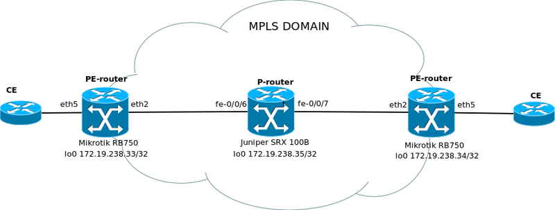
1. Mikrotik - Juniper - Mikrotik L2Circuit
Option One: Mikrotik acts as a PE router, Juniper as a P router.
Network diagram

All pictures are clickable.
Miktorik configuration as a PE router.
Raise the interfaces and IP addresses:
We configure OSPF, announce the networks through which we see our neighbors + loopback:
We configure LDP, do not forget about mpls-mtu (for successful passage of tagged packages and QinQ:
Finally, we raise L2VPN and wrap eth5 there, where our clients will live:
Cisco-style defines the id parameters by which routers recognize each other. l2-mtu determines the maximum frame size that can pass without fragmentation.
Configuring Juniper SRX as a P-router
Configuring Interfaces, IP Addresses:
Then we raise OSPF:
Finally, configure MPLS:
In this case, SRX, as a P-router, does not install any MPLS connections itself, but only passes LDP packets.
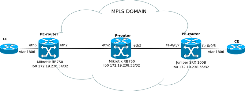
2. Juniper - Mikrotik - Mikrotik L2Circuit
Another option - now Juniper SRX acts as a PE router for us, and Mikrotik as a P router.
Network Diagram Configuring Juniper SRX as a PE Router

Of the features it is worth noting encapsulation vlan-ccc; which tells us that this port is wrapped in cross-connect. mpls-mtu must match that of another PE device.
Here we build l2circuit, specify id and mpls-mtu.
Everything is absolutely standard here, you do not need to create vpls interfaces.
3. Juniper - Mikrotik VPLS
The third option is to configure not L2circuit (aka CrossConnect Circuit in the implementation of Juniper), but a full-fledged multipoint VPLS.

Similar to the setting for l2circuit, but there are a couple of nuances:
1. Channels in one VPLS domain must have one vpls-id.
2. Connectivity should be full-mesh (each with each) to ensure the greatest reliability. However, this condition is not mandatory.
3. To get rid of the possibility of a loop, use the following option:
Configuring Juniper SRX as a PE Router
If for cross-connect we specified encapsulation vlan-ccc, then for VPLS we need encapsulation ethernet-vpls and specify family vpls in the unit settings.
VPLS-connections are also built, if possible, "each with each", although this is not necessary.
4. Checking
PE Juniper
PE Mikrotik
If the channel does not rise immediately, then turning off and on the VPLS interface from Mikrotik helps. In other cases, the channel, as they say, "either works or not."
That, in fact, is all.
5. Theory
Manuals on the topic:
1. MPLS
2. MPLS Overview
3. MPLSVPLS
4. L2VPN with Juniper
PS I apologize in advance for the large volume and large number of configs, but here, as they say, it’s better to see the config once than to go into theoretical reasoning.
PPS Moved to Network Equipment
Mikrotik RouterOS can both MPLS (L3VPN, Traffic Engeneering), and L2VPN (l2circuit aka VPWS, VPLS), which covers almost all possible tasks (given the performance of iron, of course).
Interesting? I ask for a cut!
For starters, a bit of theory.
MPLS ( multiprotocol label switching) Is a label-based routing mechanism. Each packet passing through the MPLS network, regardless of the type of packet, is assigned a specific label based on which a routing decision is made. It is important to note that the content is not studied, i.e. inside MPLS, you can drive absolutely any L2 / L3 traffic (STP, BPDU, etc., up to SDH and ATM) without any effect on the transport network (flood, vlans with a lot of mac addresses, loops and other “joys” "Become like a transport, deep purple).
The key concept in MPLS is LSP ( Label Switched Path) - the path of the packet, which is installed on the basis of the LDP, RSVP-TE, BGP or CR-LDP protocols. In this article, I will not expand on what criteria LSP is installed on, and from the protocols I will focus on LDP. Literature on MPLS on the network is enough for an interested reader to learn a lot for himself, but the purpose of this article is to demonstrate the very specific capabilities of RouterOS.
A router in an MPLS network can perform one of three functions:
1. CE-router (Client-edge) - is not a member of the MPLS network, and does not know anything about it, it's just a client device that has L2 / L3 connectivity with router provider.
2. PE-router (Provider-edge) - MPLS edge router. It is the gateway to the client and forwards its traffic to the provider's MPLS network. Another name is LER - label edge router.
3. P-router (provider router) - MPLS router that transparently passes MPLS traffic without analyzing its contents. Another name is LSR (label-switch router).
VPWS (l2circuit) - point-to-point channel (aka pseudo-wire).
VPLS is a multipoint channel, for the client it looks like a virtual "dumb" switch that transparently passes any packets.
Now that we have decided on the terminology, consider specific examples:
1. Mikrotik - Juniper - Mikrotik L2Circuit
Option One: Mikrotik acts as a PE router, Juniper as a P router.
Network diagram
All pictures are clickable.
Miktorik configuration as a PE router.
Raise the interfaces and IP addresses:
/ interface bridge
add name = loopback
add l2mtu = 1526 name = vpn
/ ip address
add address = 10.0.11.24 / 24 interface = eth2
add address = 172.19.238.33 / 32 interface = loopback network = 172.19.238.33
We configure OSPF, announce the networks through which we see our neighbors + loopback:
/ routing ospf instance
set [find default = yes] router-id = 172.19.238.33
/ routing ospf interface
add interface = eth2
/ routing ospf network
add area = backbone network = 10.0.11.0 / 24
add area = backbone network = 172.19.238.33 / 32
We configure LDP, do not forget about mpls-mtu (for successful passage of tagged packages and QinQ:
/ mpls interface
set [find default = yes] mpls-mtu = 1526
/ mpls ldp
set enabled = yes lsr-id = 172.19.238.33 transport-address = 172.19.238.33
/ mpls ldp interface
add interface = eth2
Finally, we raise L2VPN and wrap eth5 there, where our clients will live:
/ interface vpls
add advertised-l2mtu = 1526 cisco-style = yes cisco-style-id = 5 disabled = no l2mtu = 1526 \
name = junos-l2circuit remote-peer = 172.19.238.34
/ interface bridge port
add bridge = vpn interface = eth5
add bridge = vpn interface = junos-l2circuit
Cisco-style defines the id parameters by which routers recognize each other. l2-mtu determines the maximum frame size that can pass without fragmentation.
On the second PE router, the settings are similar:
/ interface bridge
add name = loopback
add l2mtu = 1526 name = vpn
/ ip address
add address = 172.19.238.34 / 32 interface = loopback network = 172.19.238.34
add address = 192.168.168.2 / 24 interface = eth2 network = 192.168.168.0
/ routing ospf instance
set [find default = yes] router-id = 172.19.238.34
/ routing ospf interface
add interface = eth2
/ routing ospf network
add area = backbone network = 192.168.168.0 / 24
add area = backbone network = 172.19.238.34 / 32
/ mpls interface
set [find default = yes] mpls-mtu = 1526
/ mpls ldp
set enabled = yes lsr-id = 172.19.238.34 transport-address = 172.19.238.34
/ mpls ldp interface
add interface = eth2
/ interface vpls
add advertised-l2mtu = 1526 cisco-style = yes cisco-style-id = 5 disabled = no l2mtu = 1526 \
name = junos-l2circuit remote-peer = 172.19.238.33
/ interface bridge port
add bridge = vpn interface = eth5
add bridge = vpn interface = junos-l2circuit
Configuring Juniper SRX as a P-router
Configuring Interfaces, IP Addresses:
interfaces {
    fe-0/0/6 {
        description mkt.192.168.168.2 - pe;
        mtu 1624;
        unit 0 {
            family inet {
                mtu 1500;
                address 192.168.168.1/24;
            }
            family mpls;
        }
    }
    fe-0/0/7 {
        description mkt.10.0.11.24 - pe;
        mtu 1624;
        unit 0 {
            family inet {
                mtu 1500;
                address 10.0.11.23/24;
            }
            family mpls;
        }
    }
    lo0 {
        unit 0 {
            family inet {
                address 172.19.238.35/32;
            }
        }
    }
}
Then we raise OSPF:
protocols {
    ospf {
        area 0.0.0.0 {
            interface fe-0/0 / 6.0 {
                hello-interval 10;
            }
            interface fe-0/0 / 7.0 {
                hello-interval 10;
            }
            interface lo0.0 {
                passive;
            }
        }
    }
}
Finally, configure MPLS:
protocols {
    mpls {
        interface all;
    }
    ldp {
        egress-policy CONNECTED-ONLY;
        transport-address 172.19.238.35;
        interface fe-0/0 / 6.0;
        interface fe-0/0 / 7.0;
        interface lo0.0;
    }
policy-options {
    prefix-list LOOPBACK-PREFIX {
        172.19.238.35/32;
    }
    policy-statement CONNECTED-ONLY {
        from {
            prefix-list LOOPBACK-PREFIX;
        }
        then accept;
    }
}
security {
    forwarding-options {
        family {
            mpls {
                mode packet-based;
            }
        }
    }
}
In this case, SRX, as a P-router, does not install any MPLS connections itself, but only passes LDP packets.
2. Juniper - Mikrotik - Mikrotik L2Circuit
Another option - now Juniper SRX acts as a PE router for us, and Mikrotik as a P router.
Network Diagram Configuring Juniper SRX as a PE Router
Interface Configuration
interfaces {
    fe-0/0/5 {
        description vpws2 - pe;
        vlan-tagging;
        mtu 1624;
        encapsulation vlan-ccc;
        unit 0 {
            encapsulation vlan-ccc;
            vlan-id 1806;
        }
    }
    fe-0/0/7 {
        description mkt.10.0.11.24 - p;
        mtu 1624;
        unit 0 {
            family inet {
                mtu 1500;
                address 10.0.11.23/24;
            }
            family mpls {
                mtu 1526;
            }
        }
    }
    lo0 {
        unit 0 {
            family inet {
                address 172.19.238.35/32;
            }
        }
    }
}
Of the features it is worth noting encapsulation vlan-ccc; which tells us that this port is wrapped in cross-connect. mpls-mtu must match that of another PE device.
Routing setup
routing-options {
    static {
        route 0.0.0.0/0 {
            next-hop 172.19.238.1;
            no-readvertise;
            preference 200;
        }
    }
}
protocols {
    mpls {
        interface all;
    }
    ospf {
        area 0.0.0.0 {
            interface fe-0/0 / 7.0 {
                hello-interval 10;
            }
            interface lo0.0 {
                passive;
            }
        }
    }
    ldp {
        egress-policy CONNECTED-ONLY;
        transport-address 172.19.238.35;
        interface all;
    }
    l2circuit {
        neighbor 172.19.238.34 {
            interface fe-0/0 / 5.0 {
                virtual-circuit-id 5;
                mtu 1526;
            }
        }
    }
}
Here we build l2circuit, specify id and mpls-mtu.
Mikrotik configuration as a P-router
/ interface bridge
add name = loopback
/ ip address
add address = 10.0.11.24 / 24 interface = eth3
add address = 172.19.238.33 / 32 interface = loopback network = 172.19.238.33
add address = 192.168.168.1 / 24 interface = eth2
/ routing ospf instance
set [find default = yes] router-id = 172.19.238.33
/ routing ospf interface
add interface = eth2
add interface = eth3
/ routing ospf network
add area = backbone network = 10.0.11.0 / 24
add area = backbone network = 172.19.238.33 / 32
add area = backbone network = 192.168.168.0 / 24
/ mpls interface
set [find default = yes] mpls-mtu = 1526
/ mpls ldp
set enabled = yes lsr-id = 172.19.238.33 transport-address = 172.19.238.33
/ mpls ldp interface
add interface = eth2
add interface = eth3
Everything is absolutely standard here, you do not need to create vpls interfaces.
3. Juniper - Mikrotik VPLS
The third option is to configure not L2circuit (aka CrossConnect Circuit in the implementation of Juniper), but a full-fledged multipoint VPLS.

Mikrotik configuration as a P-router
/ interface bridge
add name = loopback
/ ip address
add address = 10.0.11.24 / 24 interface = eth3
add address = 10.0.12.24 / 24 interface = eth5
add address = 172.19.238.33 / 32 interface = loopback network = 172.19.238.33
add address = 192.168.168.1 / 24 interface = eth2
add address = 192.168.88.1 / 24 interface = eth4
/ routing ospf instance
set [find default = yes] router-id = 172.19.238.33
/ routing ospf interface
add interface = eth2
add interface = eth3
add interface = eth4
add interface = eth5
/ routing ospf network
add area = backbone network = 10.0.11.0 / 24
add area = backbone network = 10.0.12.0 / 24
add area = backbone network = 172.19.238.33 / 32
add area = backbone network = 192.168.168.0 / 24
add area = backbone network = 192.168.88.0 / 24
/ mpls interface
set [find default = yes] mpls-mtu = 1526
/ mpls ldp
set enabled = yes lsr-id = 172.19.238.33 transport-address = 172.19.238.33
/ mpls ldp interface
add interface = eth2
add interface = eth3
add interface = eth4
add interface = eth5
Miktorik configuration as a PE router
/ interface bridge
add name = loopback
add l2mtu = 1526 name = vpn
/ ip address
add address = 172.19.238.34 / 32 interface = loopback network = 172.19.238.34
add address = 192.168.168.2 / 24 interface = eth2 network = 192.168.168.0
/ routing ospf instance
set [find default = yes] router-id = 172.19.238.34
/ routing ospf interface
add interface = eth2
/ routing ospf network
add area = backbone network = 192.168.168.0 / 24
add area = backbone network = 172.19.238.34 / 32
/ mpls interface
set [find default = yes] mpls-mtu = 1526
/ mpls ldp
set enabled = yes lsr-id = 172.19.238.34 transport-address = 172.19.238.34
/ mpls ldp interface
add interface = eth2
/ interface vpls
add advertised-l2mtu = 1526 cisco-style = yes cisco-style-id = 5 disabled = no l2mtu = 1526 \
name = junos-l2circuit remote-peer = 172.19.238.33
/ interface bridge port
add bridge = vpn interface = eth5
add bridge = vpn interface = junos-l2circuit horizon = 1
Similar to the setting for l2circuit, but there are a couple of nuances:
1. Channels in one VPLS domain must have one vpls-id.
2. Connectivity should be full-mesh (each with each) to ensure the greatest reliability. However, this condition is not mandatory.
3. To get rid of the possibility of a loop, use the following option:
/ interface bridge port set 0 horizon = 1
Configuring Juniper SRX as a PE Router
Interface Settings
interfaces {
    fe-0/0/5 {
        description vpws2 - pe;
        mtu 1624;
        encapsulation ethernet-vpls;
        unit 0 {
            family vpls;
        }
    }
    fe-0/0/6 {
        description mkt.192.168.168.2 - pe;
        mtu 1624;
        unit 0 {
            family inet {
                mtu 1500;
                address 192.168.168.1/24;
            }
            family mpls;
        }
    }
    lo0 {
        unit 0 {
            family inet {
                address 172.19.238.35/32;
            }
        }
    }
}
If for cross-connect we specified encapsulation vlan-ccc, then for VPLS we need encapsulation ethernet-vpls and specify family vpls in the unit settings.
Routing setup
protocols {
    mpls {
        interface all;
    }
    ospf {
        area 0.0.0.0 {
            interface fe-0/0 / 6.0 {
                hello-interval 10;
            }
            interface fe-0/0 / 7.0 {
                hello-interval 10;
            }
            interface lo0.0 {
                passive;
            }
        }
    }
    ldp {
        egress-policy CONNECTED-ONLY;
        transport-address 172.19.238.35;
        interface all;
    }
}
policy-options {
    prefix-list LOOPBACK-PREFIX {
        172.19.238.35/32;
    }
    policy-statement CONNECTED-ONLY {
        from {
            prefix-list LOOPBACK-PREFIX;
        }
        then accept;
    }
}
security {
    forwarding-options {
        family {
            mpls {
                mode packet-based;
            }
        }
    }
}
Configuring VPLS Connections
routing-instances {
    vpls-re {
        instance-type vpls;
        interface fe-0/0 / 5.0;
        protocols {
            vpls {
                no-tunnel-services;
                vpls-id 5;
                mtu 1526;
                neighbor 172.19.238.34;
                neighbor 172.19.238.105;
            }
        }
    }
}
VPLS-connections are also built, if possible, "each with each", although this is not necessary.
4. Checking
PE Juniper
snake @ srx1> show ldp neighbor
Address Interface Label space ID Hold time
172.19.238.34 lo0.0 172.19.238.34cript 42
10.0.11.24 fe-0/0 / 7.0 172.19.238.33cript 11
snake @ srx1> show l2circuit connections status
Layer-2 Circuit Connections:
Legend for connection status (St)
EI - encapsulation invalid NP - interface h / w not present
MM - MTU Mismatch Dn - Down
EM - encapsulation mismatch VC-Dn - Virtual circuit Down
CM - control-word mismatch Up - operational
VM - vlan id mismatch CF - Call admission control failure
OL - no outgoing label IB - TDM incompatible bitrate
NC - intf encaps not CCC / TCCTM - TDM misconfiguration
BK - Backup Connection ST - Standby Connection
CB - rcvd cell-bundle size bad SP - Static Pseudowire
LD - local site signaled down RS - remote site standby
RD - remote site signaled down XX - unknown
Legend for interface status
Up - operational
Dn - down
Neighbor: 172.19.238.34
    Interface Type St Time last up # Up trans
    fe-0/0 / 5.0 (vc 5) rmt Up Nov 9 18:27:45 2012 1
      Remote PE: 172.19.238.34, Negotiated control-word: No
      Incoming label: 300096, Outgoing label: 21
      Negotiated PW status TLV: No
      Local interface: fe-0/0 / 5.0, Status: Up, Encapsulation: VLAN
PE Mikrotik
[admin @ pe-router] / mpls ldp neighbor> print
Flags: X - disabled, D - dynamic, O - operational, T - sending-targeted-hello, V - vpls
 # TRANSPORT LOCAL-TRANSPORT PEER SEND-TARGETED ADDRESSES
0 DO 172.19.238.33 172.19.238.34 172.19.238.33cript no 10.0.11.24
                                      172.19.74.2
                                      172.19.238.33
                                      192.168.88.1
                                      192.168.168.1
1 DOTV 172.19.238.35 172.19.238.34 172.19.238.35sec yes 10.0.11.23
                                      172.19.238.4
                                      172.19.238.30
                                      172.19.238.35
                                      172.19.238.58
[admin @ pe-router] / mpls> forwarding-table print
Flags: L - ldp, V - vpls, T - traffic-eng
 # IN-LABEL OUT-LABELS DESTINATION INTERFACE NEXTHOP
 0 expl-null
 1 L 16 56 172.19.238.56/30 eth2 192.168.168.1
 2 L 17 10.0.11.0/24 eth2 192.168.168.1
 3 L 18 57 172.19.238.28/30 eth2 192.168.168.1
 4 L 19 58 172.19.238.35/32 eth2 192.168.168.1
 5 L 20 172.19.238.33/32 eth2 192.168.168.1
 6 V 21 junos-l2circuit
[admin @ pe-router]> interface vpls monitor junos-l2circuit once
       remote-label: 300096
        local-label: 21
      remote-status:
          transport: 172.19.238.35/32
  transport-nexthop: 192.168.168.1
     imposed-labels: 58,300096
If the channel does not rise immediately, then turning off and on the VPLS interface from Mikrotik helps. In other cases, the channel, as they say, "either works or not."
That, in fact, is all.
5. Theory
Manuals on the topic:
1. MPLS
2. MPLS Overview
3. MPLSVPLS
4. L2VPN with Juniper
PS I apologize in advance for the large volume and large number of configs, but here, as they say, it’s better to see the config once than to go into theoretical reasoning.
PPS Moved to Network Equipment