CSS (ISO 24730-5) Measurement of distances without tape measure and wires
In one of the previous topics, I talked about the first Russian real-time positioning system. This topic is for those who are interested, "how it works." I'll start by measuring the distance using the radio frequency method.
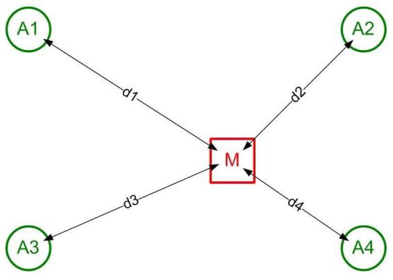
To determine the location of the marks on the plan, RTLS LLC applies a method for calculating the location of each mark based on the distances measured by the mark (M) to three or more anchors (A) having a known spatial position, as in the figure.

Two technologies are used to measure distances, namely:
CSS (Chirp Spread Spectrum) - the use of short LFM pulses and
SDS-TWR (Symmetrical Double-Sided Two Way Ranging) - a symmetrical two-way bi-directional distance measurement.
The technologies are based on measuring the propagation time of a radio signal from a transmitter to a receiver (time of flight) and comply with international standards ISO 24730-5 and IEEE 802.15.4-2011, respectively.
This topic is dedicated to CSS technology.
CSS technology, as applied by RTLS LLC, is distinguished by:
1) optimal measurement accuracy for most industrial applications (accuracy of one meter at a distance of 30 meters with a confidence of 90%) indoors;
2) high noise immunity;
3) resistance to multipath attenuation;
4) minimum power consumption tags (to increase battery life without recharging);
5) minimum cost.
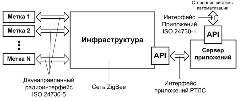
The block diagram is shown in the figure.

Distance measurements in the system are carried out by tags that exchange packets with infrastructure elements through a bi-directional radio interface that complies with ISO 24730-5. The infrastructure through the application programming interface (RTLS application API) is connected to the server to manage the infrastructure, labels and the measurement process, as well as to obtain measurement results and information about the status of the labels. The infrastructure in the RTLS system is composed of ZigBee wireless mesh zones (IEEE 802.15.4) connected to the server by IP channels. Each ZigBee network base station has an additional radio interface for tagging. (One of the following topics will be devoted to RTLS infrastructure).
The server, in turn, has an external standard API that allows you to transfer the data received by the system to other automated systems.
In the RTLS system, tags are not part of the network, do not participate in routing and data transmission, that is, are exempt from everything except measuring distances and transmitting the measurement results through the transport network to the server. This allowed us to simplify tags and reduce their energy consumption and price.
The tags interact with the infrastructure through the bidirectional radio interface shown in the figure.

For this interface, the ISO 24730-5 standard defines the frequency range, radio waveform, modulation, coding, packet formats, commands and other parameters. The interface protocol stack includes:
PHY- the physical layer, which determines the parameters of the transmission medium (operating frequency, channel width, etc.);
MAC - the level of access to the environment, which determines the encoding parameters, packet format, and the like;
API - the application level, which determines the status of the label and the order in which they change, a list of commands and their parameters, protocols for exchanging packets with infrastructure elements, and so on.
At the moment of switching on, the status of the label is initial, the “default profile” is used. The label periodically sends out short broadcast packets - blinks. Each blink contains the physical address of the tag, its status and information about the time when the tag will be ready to receive commands from the infrastructure.
Infrastructure with the appropriate commands indicates the label with what anchors and with what frequency to measure distances, the number of measurement sessions and the address for transmitting the results. The behavior of the labels is changed by transmitting the appropriate commands by changing the status of the labels and setting the measurement modes and parameters.
If the label does not receive the next command at a certain time, it returns to its initial state (to use the "default profile") and periodically sends out blinks to restore communication. You can read more about label states and control commands in the appendix to the article on the RTLS website www.rtlsnet.ru/technology/view/2 .
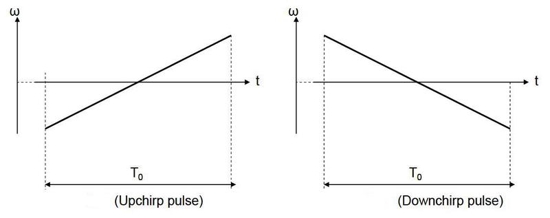
CSS technology uses “chirp” pulses (in the literal translation chirp means tweet, and in Russian, CSS stands for linear frequency modulation - chirp). Chirp pulses are pulses of a monotonically increasing or decreasing frequency. The lower and upper frequencies of the chirp pulse correspond to the limits of the frequency range specified by the standard.
In nature, dolphins and bats have been measuring distances for millions of years using Chirp pulses. In chirp radar, pulses were first used and patented by Professor Guttman in 1940. Canon in the mid-1990s patented the use of chirp pulses in fiber optic systems. And in 1996, Nanotron Technologies began research and subsequently patented CSS for wireless data transfer.
CSS is radio frequency technology and is best suited for applications where communication reliability and low power consumption are especially important for battery-powered devices. CSS data transfer speed is average (up to 2 Mb / s).
Any CSS packet is transmitted by Chirp in two types of pulses: with increasing (Upchirp) or decreasing (Downchirp) frequency, as shown in the figures.


The ISO 24730-5 standard establishes a center frequency of 2.45 GHz for CSS, a bandwidth of 80 MHz, and a fixed pulse width of 1 μs.
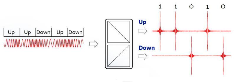
In CSS technology, information is transmitted using a coded sequence of Chirp pulses. Symbol “1” corresponds to Upchirp impulse, symbol “0” - Downchirp impulse. Decoding a sequence is carried out by two complementary (complementary) dispersion delay lines (DLZ). The coded sequence is fed to the inputs of both lines, but the parameters of the DLZ are selected so that signals of different frequencies pass through the DLZ at different speeds. In one DLZ (in the figure - Up), high frequencies propagate through the delay line faster, in the second, lower frequencies are faster. As a result, Upchirp impulse, which begins with low and ends with high frequencies, passing through DLZ Up "is compressed" in time. The high-frequency end “catches up” the low-frequency beginning and the pulse energy at the output initially uniformly distributed over time appears in a short pulse, the amplitude of which turns out to be many times larger than the amplitude of the input signal. On the contrary, the Downchirp impulse, passing through the DLZ Up, “erodes” in time and its amplitude decreases. Thus, pulses that correspond to the symbol "1" appear at the output of the DLZ Up. In the second DLZ (in the Down picture), low frequencies propagate faster, due to which Downchirp pulses are “compressed”, and pulses that correspond to the “0” symbol appear at the DLZ output. "Blurred" in time and its amplitude decreases. Thus, pulses that correspond to the symbol "1" appear at the output of the DLZ Up. In the second DLZ (in the Down picture), low frequencies propagate faster, due to which Downchirp pulses are “compressed”, and pulses that correspond to the “0” symbol appear at the DLZ output. "Blurred" in time and its amplitude decreases. Thus, pulses that correspond to the symbol "1" appear at the output of the DLZ Up. In the second DLZ (in the Down picture), low frequencies propagate faster, due to which Downchirp pulses are “compressed”, and pulses that correspond to the “0” symbol appear at the DLZ output.

In addition to decoding, DLZs increase the immunity to interference, as well as to broadband noise. The bottom line is that interference (noise), unlike chirp pulses, have an unchanged frequency spectrum and pass through the DLZ without changes. The “compressed” chirp pulses in the DLZ have a large amplitude compared to the initial amplitude, and are easily distinguished from noise and noise.
Another advantage of CSS is its resistance to multipath attenuation. A transmitter signal in the 2.4 GHz band usually reaches the receiver in the "accompaniment" of several echo signals - reflections from obstacles, or even only in the form of echo signals in the absence of direct visibility. The signal propagation paths have different lengths, so the reflections are out of phase with respect to the main signal. In narrow-band systems, this leads to communication disruption. CSS differs in that the distorted and phase-shifted signals generally preserve the frequency spectrum, which makes it possible to collect practically all of the energy distributed in the 80 megahertz band of the original signal at the DLZ.
To determine the location of the marks on the plan, RTLS LLC applies a method for calculating the location of each mark based on the distances measured by the mark (M) to three or more anchors (A) having a known spatial position, as in the figure.

Two technologies are used to measure distances, namely:
CSS (Chirp Spread Spectrum) - the use of short LFM pulses and
SDS-TWR (Symmetrical Double-Sided Two Way Ranging) - a symmetrical two-way bi-directional distance measurement.
The technologies are based on measuring the propagation time of a radio signal from a transmitter to a receiver (time of flight) and comply with international standards ISO 24730-5 and IEEE 802.15.4-2011, respectively.
This topic is dedicated to CSS technology.
CSS technology, as applied by RTLS LLC, is distinguished by:
1) optimal measurement accuracy for most industrial applications (accuracy of one meter at a distance of 30 meters with a confidence of 90%) indoors;
2) high noise immunity;
3) resistance to multipath attenuation;
4) minimum power consumption tags (to increase battery life without recharging);
5) minimum cost.
RTLS Positioning System Structure
The block diagram is shown in the figure.

Distance measurements in the system are carried out by tags that exchange packets with infrastructure elements through a bi-directional radio interface that complies with ISO 24730-5. The infrastructure through the application programming interface (RTLS application API) is connected to the server to manage the infrastructure, labels and the measurement process, as well as to obtain measurement results and information about the status of the labels. The infrastructure in the RTLS system is composed of ZigBee wireless mesh zones (IEEE 802.15.4) connected to the server by IP channels. Each ZigBee network base station has an additional radio interface for tagging. (One of the following topics will be devoted to RTLS infrastructure).
The server, in turn, has an external standard API that allows you to transfer the data received by the system to other automated systems.
In the RTLS system, tags are not part of the network, do not participate in routing and data transmission, that is, are exempt from everything except measuring distances and transmitting the measurement results through the transport network to the server. This allowed us to simplify tags and reduce their energy consumption and price.
The tags interact with the infrastructure through the bidirectional radio interface shown in the figure.

For this interface, the ISO 24730-5 standard defines the frequency range, radio waveform, modulation, coding, packet formats, commands and other parameters. The interface protocol stack includes:
PHY- the physical layer, which determines the parameters of the transmission medium (operating frequency, channel width, etc.);
MAC - the level of access to the environment, which determines the encoding parameters, packet format, and the like;
API - the application level, which determines the status of the label and the order in which they change, a list of commands and their parameters, protocols for exchanging packets with infrastructure elements, and so on.
System operation
At the moment of switching on, the status of the label is initial, the “default profile” is used. The label periodically sends out short broadcast packets - blinks. Each blink contains the physical address of the tag, its status and information about the time when the tag will be ready to receive commands from the infrastructure.
Infrastructure with the appropriate commands indicates the label with what anchors and with what frequency to measure distances, the number of measurement sessions and the address for transmitting the results. The behavior of the labels is changed by transmitting the appropriate commands by changing the status of the labels and setting the measurement modes and parameters.
If the label does not receive the next command at a certain time, it returns to its initial state (to use the "default profile") and periodically sends out blinks to restore communication. You can read more about label states and control commands in the appendix to the article on the RTLS website www.rtlsnet.ru/technology/view/2 .
Distance Measuring Technology: Chirp Spread Spectrum (CSS)
CSS technology uses “chirp” pulses (in the literal translation chirp means tweet, and in Russian, CSS stands for linear frequency modulation - chirp). Chirp pulses are pulses of a monotonically increasing or decreasing frequency. The lower and upper frequencies of the chirp pulse correspond to the limits of the frequency range specified by the standard.
In nature, dolphins and bats have been measuring distances for millions of years using Chirp pulses. In chirp radar, pulses were first used and patented by Professor Guttman in 1940. Canon in the mid-1990s patented the use of chirp pulses in fiber optic systems. And in 1996, Nanotron Technologies began research and subsequently patented CSS for wireless data transfer.
CSS is radio frequency technology and is best suited for applications where communication reliability and low power consumption are especially important for battery-powered devices. CSS data transfer speed is average (up to 2 Mb / s).
How it works
Any CSS packet is transmitted by Chirp in two types of pulses: with increasing (Upchirp) or decreasing (Downchirp) frequency, as shown in the figures.


The ISO 24730-5 standard establishes a center frequency of 2.45 GHz for CSS, a bandwidth of 80 MHz, and a fixed pulse width of 1 μs.
In CSS technology, information is transmitted using a coded sequence of Chirp pulses. Symbol “1” corresponds to Upchirp impulse, symbol “0” - Downchirp impulse. Decoding a sequence is carried out by two complementary (complementary) dispersion delay lines (DLZ). The coded sequence is fed to the inputs of both lines, but the parameters of the DLZ are selected so that signals of different frequencies pass through the DLZ at different speeds. In one DLZ (in the figure - Up), high frequencies propagate through the delay line faster, in the second, lower frequencies are faster. As a result, Upchirp impulse, which begins with low and ends with high frequencies, passing through DLZ Up "is compressed" in time. The high-frequency end “catches up” the low-frequency beginning and the pulse energy at the output initially uniformly distributed over time appears in a short pulse, the amplitude of which turns out to be many times larger than the amplitude of the input signal. On the contrary, the Downchirp impulse, passing through the DLZ Up, “erodes” in time and its amplitude decreases. Thus, pulses that correspond to the symbol "1" appear at the output of the DLZ Up. In the second DLZ (in the Down picture), low frequencies propagate faster, due to which Downchirp pulses are “compressed”, and pulses that correspond to the “0” symbol appear at the DLZ output. "Blurred" in time and its amplitude decreases. Thus, pulses that correspond to the symbol "1" appear at the output of the DLZ Up. In the second DLZ (in the Down picture), low frequencies propagate faster, due to which Downchirp pulses are “compressed”, and pulses that correspond to the “0” symbol appear at the DLZ output. "Blurred" in time and its amplitude decreases. Thus, pulses that correspond to the symbol "1" appear at the output of the DLZ Up. In the second DLZ (in the Down picture), low frequencies propagate faster, due to which Downchirp pulses are “compressed”, and pulses that correspond to the “0” symbol appear at the DLZ output.

In addition to decoding, DLZs increase the immunity to interference, as well as to broadband noise. The bottom line is that interference (noise), unlike chirp pulses, have an unchanged frequency spectrum and pass through the DLZ without changes. The “compressed” chirp pulses in the DLZ have a large amplitude compared to the initial amplitude, and are easily distinguished from noise and noise.
Another advantage of CSS is its resistance to multipath attenuation. A transmitter signal in the 2.4 GHz band usually reaches the receiver in the "accompaniment" of several echo signals - reflections from obstacles, or even only in the form of echo signals in the absence of direct visibility. The signal propagation paths have different lengths, so the reflections are out of phase with respect to the main signal. In narrow-band systems, this leads to communication disruption. CSS differs in that the distorted and phase-shifted signals generally preserve the frequency spectrum, which makes it possible to collect practically all of the energy distributed in the 80 megahertz band of the original signal at the DLZ.
