Using Blender and FreeCad to import 3D component models into KiCad
KiCad is an excellent program for the design of printed circuit boards, allowing you to create fairly complex projects. It supports three-dimensional visualization of the product, which can be very useful for finding errors in the topology or design.
There is only one disadvantage: KiCad does not support the widespread step format . Many manufacturers of electronic components provide 3D-models of their products in this form. And to use these files, you have to convert them to vrml format , understood by KiCad.
Methods for converting and connecting the model are not entirely obvious, especially when using free software.
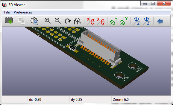
In this article I will tell you how to convert a 3D model of an object to connect it to a landing pad in the KiCad library without registration and SMS.
If you decide to familiarize yourself with the material below, I dare to assume that you already have installed KiCad and have some experience in creating printed circuit boards. Therefore, I will not describe the features of creating libraries and landing sites.
To work we need two programs - Blender and FreeCad .
We will use Blender to fit and convert models to vrml format, understood by KiCad.
And FreeCad for intermediate conversion of step-format to stl-format, since blender does not know how to work with the first one.
In fact, FreeCad can immediately convert step to vrml. But he does it not always correctly: sometimes the converted file is not read by KiCad, and often the fitting in size and position of the object takes a lot of time. Blender greatly simplifies the process of linking a 3D model to a landing site.
There is another feature related to the fact that KiCad interprets all the sizes of objects in the vrml-file in inches. Therefore, imported models without scaling are often displayed enlarged. At the same time, they are almost always shifted relative to the center and not correctly rotated relative to the board and the landing pad. To make the display correct, you need to set the scale and position either in the vrml-model or in the component settings in the KiCad library. In my opinion, it is more correct to adjust the coefficients in the vrml-file. The finished file should be opened in any KiCad library without subsequent conversions.
The principle of 3D-model binding will be considered on the example of a not complicated Molex 505433-1071 connector
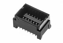
All the necessary information - a drawing of the landing pad and a 3D model is available on the manufacturer's website. Download the required step-model.
To begin with, the resulting Step-model is converted into stl-format. To do this, run FreeCad and open the file with the connector.
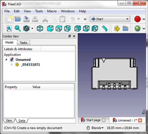
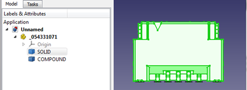
To export to the stl format, we need to select a solid model and, using File-> Export, save it in the format we need.
We don’t need FreeCad anymore, we can close it, launch Blender.
The basics of working with the editor are beyond the scope of this article. If you didn’t have to work with this program before, you can watch a couple of initial training videos. Navigation skills in the workspace and elementary work with objects should be sufficient for our purposes.
If the standard initial window is opened, then we delete all three elements present on the stage: a cube, a camera, and a light source. The start window may look slightly different than shown in the figure below, but this is not important now.
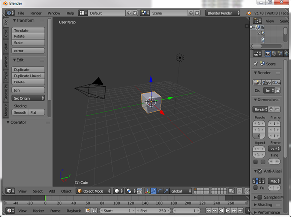
We can select all three elements using the “A” key (right-clicking will remove the selection from all objects, the second will select all objects on the stage). Next, using the "X" key, we delete all unnecessary objects.

Now we can import our stl model: File-> Import-> Stl.
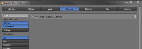
If there is no such menu, then go to File-> User Preferences ... -> Add-ons. In the search we drive in stl and check the box opposite to Import-Export STL format
After importing some models (as in our case), we can observe an absolutely empty scene:

Most likely the object is outside the scene, and in the center is only the anchor point of the object. Zoom out and see that the connector is indeed far from the origin.

Move it for convenience to the center.
Press the key "5" (switch the view on the isometric projection ) and "1" (switch the view in front view) on the additional numeric keypad.
Select the connector, press the keys "G" (move) and "Z" (move only along the Z axis). Next, we move the object approximately to the origin of coordinates along the Z axis.
Then go to the right view by pressing the “3” button on the additional keyboard. And with the help of the combination “G” + “Y” we move the object to the origin along the axis “Y”.
And in conclusion, we perform the same operation for the top view: the keys “7”, “G”, “X”.
As a result, our model is located approximately in the center of coordinates. Only its binding point is far beyond the object itself, which does not suit us. Therefore, we translate the 3D cursor to the origin using the “Shift” + “C” combination and set this point as the anchor point Edit-> Set Origin-> Origin to 3D Cursor:

Now it’s more convenient to work with the connector both in Blender and in kicad. In order to make the connector easier to import into KiCad in this case, it is best to place it in such a way that the origin of coordinates is on its middle contact surface at its center. Switching between different types by the method described earlier, we adjust its location to the necessary.
After completing the preliminary location, we export the model as vrml.
File-> Export-> VRML2.
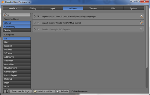
If there is no such menu, first go to File-> User Preferences ... -> Add-ons. In the search we drive in vrml and check the box opposite Import-Export VRML2 and Import-Export Web3D X3D / VRML2 format.
Select the path where you want to save the file, set the name. In the Scale field, enter the magic number 0.393701. The fact is that KiCad wants to see all measurements in inches, but we have them, hmm ... in conventional units - centimeters. In one centimeter - 0,393701 inches.
We press the export button and see the result in KiCad.
Create a new component. And immediately in the settings we can bind our model:
Edit-> Footprint Properties-> 3D settings -> Add 3D Shape.
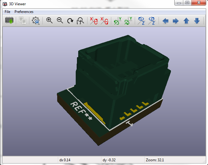
We open the 3D view and see that our model has successfully loaded.

If the model is rotated relative to the board in any direction, then we fix it in Blender: press the “R” key - to rotate the object, and “X”, “Y” or “ Z ”to rotate only in one of the appropriately selected planes. Next, we drive in the rotation angle - “90”, “-90” or any other angle, and complete the operation by pressing enter. Export the model again, and update the view in KiCad's 3D view.
All actions to shift the model are more convenient to perform in Blender. In KiCad, all changes need to be specified in numbers in inches, which is not at all friendly for us, who are used to seeing millimeters everywhere.
If in Blender we located the center of coordinates exactly below the middle pin of the connector, then we can locate the corresponding contact exactly in the center of our new component.
By creating a landing pad, it is possible to assess whether the conclusions of the future chip are correctly located in the PCB by comparing the location of the contact pads with the three-dimensional image.
In the next article, I will describe how to create an exact model of the electronic component in Blender for its subsequent import into KiCad. The task at first glance is simple. But there are several features associated with the fact that in Blender you cannot, like in modern CAD systems, specify the exact dimensions of objects in millimeters. But by adjusting yourself, you can create accurate models, even suitable for checking the created landing sites.
There is only one disadvantage: KiCad does not support the widespread step format . Many manufacturers of electronic components provide 3D-models of their products in this form. And to use these files, you have to convert them to vrml format , understood by KiCad.
Methods for converting and connecting the model are not entirely obvious, especially when using free software.

In this article I will tell you how to convert a 3D model of an object to connect it to a landing pad in the KiCad library without registration and SMS.
If you decide to familiarize yourself with the material below, I dare to assume that you already have installed KiCad and have some experience in creating printed circuit boards. Therefore, I will not describe the features of creating libraries and landing sites.
To work we need two programs - Blender and FreeCad .
We will use Blender to fit and convert models to vrml format, understood by KiCad.
And FreeCad for intermediate conversion of step-format to stl-format, since blender does not know how to work with the first one.
In fact, FreeCad can immediately convert step to vrml. But he does it not always correctly: sometimes the converted file is not read by KiCad, and often the fitting in size and position of the object takes a lot of time. Blender greatly simplifies the process of linking a 3D model to a landing site.
There is another feature related to the fact that KiCad interprets all the sizes of objects in the vrml-file in inches. Therefore, imported models without scaling are often displayed enlarged. At the same time, they are almost always shifted relative to the center and not correctly rotated relative to the board and the landing pad. To make the display correct, you need to set the scale and position either in the vrml-model or in the component settings in the KiCad library. In my opinion, it is more correct to adjust the coefficients in the vrml-file. The finished file should be opened in any KiCad library without subsequent conversions.
The principle of 3D-model binding will be considered on the example of a not complicated Molex 505433-1071 connector

All the necessary information - a drawing of the landing pad and a 3D model is available on the manufacturer's website. Download the required step-model.
To begin with, the resulting Step-model is converted into stl-format. To do this, run FreeCad and open the file with the connector.

To export to the stl format, we need to select a solid model and, using File-> Export, save it in the format we need.

We don’t need FreeCad anymore, we can close it, launch Blender.
The basics of working with the editor are beyond the scope of this article. If you didn’t have to work with this program before, you can watch a couple of initial training videos. Navigation skills in the workspace and elementary work with objects should be sufficient for our purposes.
If the standard initial window is opened, then we delete all three elements present on the stage: a cube, a camera, and a light source. The start window may look slightly different than shown in the figure below, but this is not important now.

We can select all three elements using the “A” key (right-clicking will remove the selection from all objects, the second will select all objects on the stage). Next, using the "X" key, we delete all unnecessary objects.

Now we can import our stl model: File-> Import-> Stl.
If there is no such menu, then go to File-> User Preferences ... -> Add-ons. In the search we drive in stl and check the box opposite to Import-Export STL format

After importing some models (as in our case), we can observe an absolutely empty scene:

Most likely the object is outside the scene, and in the center is only the anchor point of the object. Zoom out and see that the connector is indeed far from the origin.

Move it for convenience to the center.
Press the key "5" (switch the view on the isometric projection ) and "1" (switch the view in front view) on the additional numeric keypad.
Select the connector, press the keys "G" (move) and "Z" (move only along the Z axis). Next, we move the object approximately to the origin of coordinates along the Z axis.
Then go to the right view by pressing the “3” button on the additional keyboard. And with the help of the combination “G” + “Y” we move the object to the origin along the axis “Y”.
And in conclusion, we perform the same operation for the top view: the keys “7”, “G”, “X”.
As a result, our model is located approximately in the center of coordinates. Only its binding point is far beyond the object itself, which does not suit us. Therefore, we translate the 3D cursor to the origin using the “Shift” + “C” combination and set this point as the anchor point Edit-> Set Origin-> Origin to 3D Cursor:

Now it’s more convenient to work with the connector both in Blender and in kicad. In order to make the connector easier to import into KiCad in this case, it is best to place it in such a way that the origin of coordinates is on its middle contact surface at its center. Switching between different types by the method described earlier, we adjust its location to the necessary.
After completing the preliminary location, we export the model as vrml.
File-> Export-> VRML2.
If there is no such menu, first go to File-> User Preferences ... -> Add-ons. In the search we drive in vrml and check the box opposite Import-Export VRML2 and Import-Export Web3D X3D / VRML2 format.

Select the path where you want to save the file, set the name. In the Scale field, enter the magic number 0.393701. The fact is that KiCad wants to see all measurements in inches, but we have them, hmm ... in conventional units - centimeters. In one centimeter - 0,393701 inches.
We press the export button and see the result in KiCad.
Create a new component. And immediately in the settings we can bind our model:
Edit-> Footprint Properties-> 3D settings -> Add 3D Shape.
We open the 3D view and see that our model has successfully loaded.

If the model is rotated relative to the board in any direction, then we fix it in Blender: press the “R” key - to rotate the object, and “X”, “Y” or “ Z ”to rotate only in one of the appropriately selected planes. Next, we drive in the rotation angle - “90”, “-90” or any other angle, and complete the operation by pressing enter. Export the model again, and update the view in KiCad's 3D view.
All actions to shift the model are more convenient to perform in Blender. In KiCad, all changes need to be specified in numbers in inches, which is not at all friendly for us, who are used to seeing millimeters everywhere.
If in Blender we located the center of coordinates exactly below the middle pin of the connector, then we can locate the corresponding contact exactly in the center of our new component.
By creating a landing pad, it is possible to assess whether the conclusions of the future chip are correctly located in the PCB by comparing the location of the contact pads with the three-dimensional image.

In the next article, I will describe how to create an exact model of the electronic component in Blender for its subsequent import into KiCad. The task at first glance is simple. But there are several features associated with the fact that in Blender you cannot, like in modern CAD systems, specify the exact dimensions of objects in millimeters. But by adjusting yourself, you can create accurate models, even suitable for checking the created landing sites.
