Miniature USB programmer for AVR microcontrollers
As a theater begins with a hanger, so programming microcontrollers begins with choosing a good programmer. As I begin to master the ATMEL microcontrollers, I had to thoroughly familiarize myself with what the manufacturers offer. They offer a lot of everything interesting and tasty, only at absolutely sky-high prices. For example, a scarf with one twenty-foot microcontroller with a pair of resistors and diodes as a strapping, stands like a “plane”. Therefore, the question arose of self-assembly of the programmer. After a long study of the experience of radio amateurs with experience, it was decided to assemble a well-proven USBASP programmer, whose brain is the Atmega8 microcontroller (there are also firmware options for atmega88 and atmega48). The minimum binding of the microcontroller allows you to assemble a fairly miniature programmer,
The author of this programmer is the German Thomas Fichl, a page of its development with diagrams, printed circuit board files and drivers.
Once it was decided to assemble a miniature programmer, I redrawn the circuit for the Atmega8 microcontroller in the TQFP32 package (the pinout of the microcontroller is different from the pinout in the DIP package):

J1 jumper is used if it is necessary to flash a microcontroller with a clock frequency below 1.5 MHz. By the way, this jumper can generally be excluded by planting the 25th foot of MK on the ground. Then the programmer will always work at a lower frequency. I personally noted that programming at a reduced speed is a split second longer, and therefore now I do not jerk the jumper, but constantly sew with it.
Zener diodes D1 and D2 are used to coordinate levels between the programmer and the USB bus, it will work without them, but not on all computers.
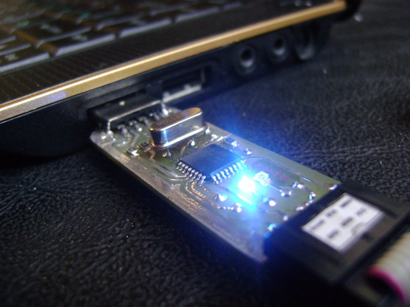
The blue LED indicates that the circuit is ready for programming, red lights up during programming. The programming contacts are output to the IDC-06 connector, the pinout conforms to the ATMEL standard for a 6-pin ISP connector:
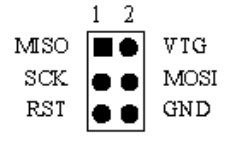
The contacts for powering the programmable devices are connected to this connector, here it is taken directly from the USB port of the computer, so you need to be careful and not allow short circuit. The same connector is also used for programming the control microcontroller, for this it is enough to connect the Reset leads on the connector and to microns (see the red dotted line in the diagram). In the author's scheme, this is done by a jumper, but I did not clutter up the board and removed it. For a single firmware, a simple wire jumper is enough. The board turned out to be double-sided, measuring 45x18 mm.
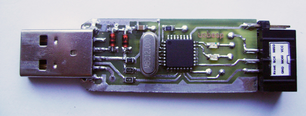
The programming connector and jumper to reduce the speed of the programmer are moved to the end of the device, it is very convenient

So, after assembling the device, the most important thing remains - to flash the control microcontroller. For these purposes, friends who have computers with an LPT port are well suited :) The simplest five-wire programmer for AVR
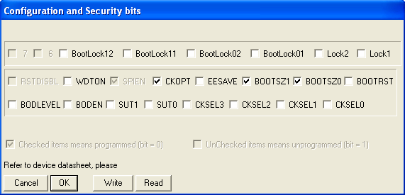
The microcontroller can be flashed from the programming connector by connecting the Reset pins of the microcontroller (29 legs) and the connector. The firmware exists for the Atmega48, Atmega8, and Atmega88 models. It is advisable to use one of the last two stones, since support for the version for Atmega48 has been discontinued and the latest firmware version dates from 2009. And the versions for the 8th and 88th stones are constantly updated, and the author seems to be planning to add an in-circuit debugger to the functionality. We take the firmware on the German page. To fill the control program into the microcontroller, I used the PonyProg program. When programming, it is necessary to start the crystal to work from an external clock source at 12 MHz. Screen of the program with fuse jumper settings in PonyProg:
After flashing, the LED connected to the 23rd leg of the microcontroller should light up. This will be a sure sign that the programmer has been flashed successfully and is ready to work.
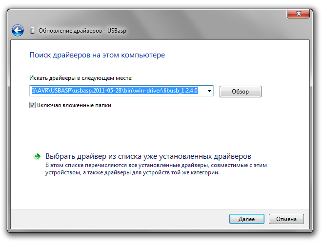
Installation was carried out on a machine with Windows 7 and no problems arose. The first time you connect to a computer, a message appears stating that a new device has been found, suggesting you install the driver. We select the installation from the specified location:

Select the folder where the firewood is located and click Next.
A window will pop up with a warning that the installed driver does not have a digital signature for the
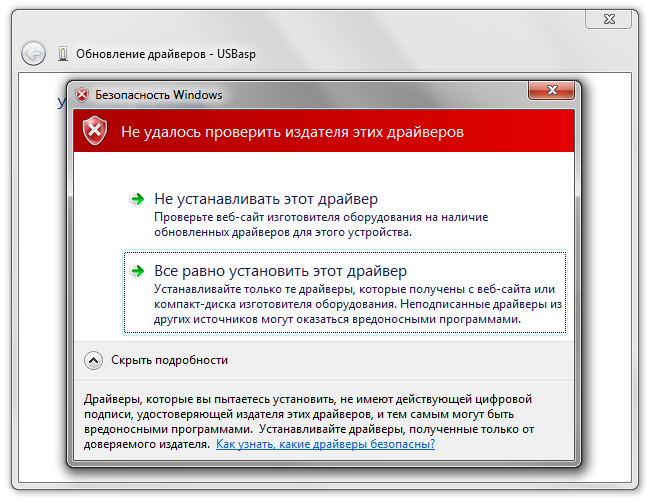
soft ones : Forget the warning and continue the installation, after a short pause a window appears informing of the successful completion of the operation driver installation

Everything, now the programmer is ready to work.
To work with the programmer, I chose the Khazama AVR Programmer . Wonderful program with a minimalistic interface.
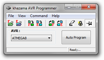
It works with all running AVR microcontrollers, allows you to flash flash and eeprom, view the contents of the memory, erase the chip, and change the configuration of fuse bits. In general, a completely standard set. The fuses are set up by selecting the clock source from the drop-down list, thus, the probability of locking the crystal by mistake is sharply reduced. Fusion can be changed by arranging jackdaws in the lower field, while you can not arrange jackdaws on a nonexistent configuration, and this is also a big plus in terms of security.
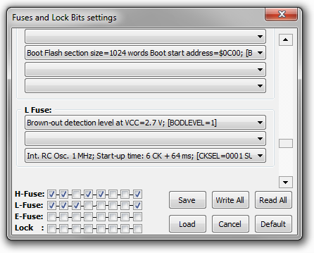
As you might guess, the recording of fuses in the memory of microns is carried out by pressing the Write All button. The Save button saves the current configuration, and Load returns the saved one. True, I could not come up with the practical application of these buttons. The Default button is used to record the standard configuration of fuses, such as the one used by microcontrollers from the factory (usually 1 MHz from internal RC).
In general, for all the time using this programmer, he showed himself from the best side in terms of stability and speed. It worked without problems both on an ancient stationary PC and on a new laptop.
You can download the PCB file in SprintLayout at this link.
Well, like everything, if you have any questions, I will try to answer.
The author of this programmer is the German Thomas Fichl, a page of its development with diagrams, printed circuit board files and drivers.
Once it was decided to assemble a miniature programmer, I redrawn the circuit for the Atmega8 microcontroller in the TQFP32 package (the pinout of the microcontroller is different from the pinout in the DIP package):
J1 jumper is used if it is necessary to flash a microcontroller with a clock frequency below 1.5 MHz. By the way, this jumper can generally be excluded by planting the 25th foot of MK on the ground. Then the programmer will always work at a lower frequency. I personally noted that programming at a reduced speed is a split second longer, and therefore now I do not jerk the jumper, but constantly sew with it.
Zener diodes D1 and D2 are used to coordinate levels between the programmer and the USB bus, it will work without them, but not on all computers.
The blue LED indicates that the circuit is ready for programming, red lights up during programming. The programming contacts are output to the IDC-06 connector, the pinout conforms to the ATMEL standard for a 6-pin ISP connector:
The contacts for powering the programmable devices are connected to this connector, here it is taken directly from the USB port of the computer, so you need to be careful and not allow short circuit. The same connector is also used for programming the control microcontroller, for this it is enough to connect the Reset leads on the connector and to microns (see the red dotted line in the diagram). In the author's scheme, this is done by a jumper, but I did not clutter up the board and removed it. For a single firmware, a simple wire jumper is enough. The board turned out to be double-sided, measuring 45x18 mm.
The programming connector and jumper to reduce the speed of the programmer are moved to the end of the device, it is very convenient
Firmware control microcontroller
So, after assembling the device, the most important thing remains - to flash the control microcontroller. For these purposes, friends who have computers with an LPT port are well suited :) The simplest five-wire programmer for AVR
The microcontroller can be flashed from the programming connector by connecting the Reset pins of the microcontroller (29 legs) and the connector. The firmware exists for the Atmega48, Atmega8, and Atmega88 models. It is advisable to use one of the last two stones, since support for the version for Atmega48 has been discontinued and the latest firmware version dates from 2009. And the versions for the 8th and 88th stones are constantly updated, and the author seems to be planning to add an in-circuit debugger to the functionality. We take the firmware on the German page. To fill the control program into the microcontroller, I used the PonyProg program. When programming, it is necessary to start the crystal to work from an external clock source at 12 MHz. Screen of the program with fuse jumper settings in PonyProg:
After flashing, the LED connected to the 23rd leg of the microcontroller should light up. This will be a sure sign that the programmer has been flashed successfully and is ready to work.
Driver installation
Installation was carried out on a machine with Windows 7 and no problems arose. The first time you connect to a computer, a message appears stating that a new device has been found, suggesting you install the driver. We select the installation from the specified location:
Select the folder where the firewood is located and click Next.
A window will pop up with a warning that the installed driver does not have a digital signature for the
soft ones : Forget the warning and continue the installation, after a short pause a window appears informing of the successful completion of the operation driver installation
Everything, now the programmer is ready to work.
Khazama AVR Programmer
To work with the programmer, I chose the Khazama AVR Programmer . Wonderful program with a minimalistic interface.
It works with all running AVR microcontrollers, allows you to flash flash and eeprom, view the contents of the memory, erase the chip, and change the configuration of fuse bits. In general, a completely standard set. The fuses are set up by selecting the clock source from the drop-down list, thus, the probability of locking the crystal by mistake is sharply reduced. Fusion can be changed by arranging jackdaws in the lower field, while you can not arrange jackdaws on a nonexistent configuration, and this is also a big plus in terms of security.
As you might guess, the recording of fuses in the memory of microns is carried out by pressing the Write All button. The Save button saves the current configuration, and Load returns the saved one. True, I could not come up with the practical application of these buttons. The Default button is used to record the standard configuration of fuses, such as the one used by microcontrollers from the factory (usually 1 MHz from internal RC).
In general, for all the time using this programmer, he showed himself from the best side in terms of stability and speed. It worked without problems both on an ancient stationary PC and on a new laptop.
You can download the PCB file in SprintLayout at this link.
Well, like everything, if you have any questions, I will try to answer.