Draw a cartoon explosion for 180 lines of naked C ++
- Tutorial
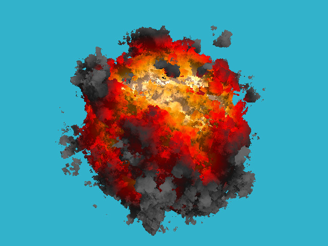
A week ago, I published another chapter from my lecture course on computer graphics ; today we are back to ray tracing, but this time we’ll go a little further on drawing the trivial spheres. I do not need photorealism, for cartoon purposes such an explosion , it seems to me, will come down.
As always, we have only the bare compiler at our disposal, no third-party libraries can be used. I don't want to bother with window managers, mouse / keyboard handling, and the like. The result of our program will be a simple image saved to disk. I absolutely do not chase for speed / optimization, my goal is to show the basic principles.
Total, how in such conditions to draw just such a picture for 180 lines of code?
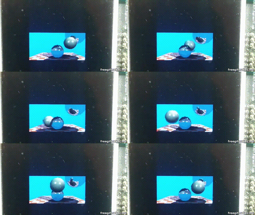
Let me even insert an animated gif (six meters):

And now we divide the whole task into several stages:
Yes exactly. The very first thing you need to read the previous chapter , which tells about the basics of ray tracing. It is quite short, in principle, you can not read any reflections, refractions, but at least I should recommend to finish reading diffused lighting. The code is quite simple, the people run it even on microcontrollers:
Let's draw one sphere without bothering with materials or lighting. For simplicity, this sphere will live in the center of coordinates. About this picture I want to get:

Look at the code here , but let me give you the main one right in the text of the article:
The class of vectors lives in the geometry.h file, I will not describe it here: first, everything is trivial, simple manipulation of two and three-dimensional vectors (addition, subtraction, assignment, scalar multiplication, scalar production), and second, gbg has already described it in detail as part of a course on computer graphics.
I save the picture in ppm format ; This is the easiest way to save images, although it is not always the most convenient for further viewing.
So, in the function main (), I have two cycles: the second cycle simply saves the image to the disk, and the first cycle passes through all the pixels of the image, emits a beam from the camera through this pixel, and looks to see if this beam intersects with our sphere.
Attention, the main idea of the article: if in the last article we analytically considered the intersection of the ray and the sphere, now I consider it numerically. The idea is simple: a sphere has an equation of the form x ^ 2 + y ^ 2 + z ^ 2 - r ^ 2 = 0; but in general the function f (x, y, z) = x ^ 2 + y ^ 2 + z ^ 2 - r ^ 2 is defined in the whole space. Inside the sphere, the function f (x, y, z) will have negative values, and outside the sphere will be positive. That is, the function f (x, y, z) for the point (x, y, z) sets the distance (with a sign!) To our sphere. Therefore, we will simply slide along the ray until either we are bored or the function f (x, y, z) becomes negative. The function sphere_trace () does just that.
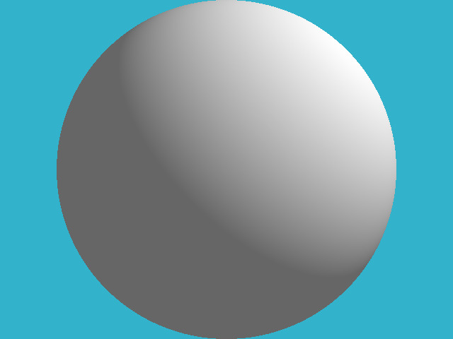
Let's code the simplest diffuse lighting, this is the picture I want to get at the output:
As in the previous article, for ease of reading I made one stage = one commit. Changes can be viewed here .
For diffuse illumination it is not enough for us to calculate the point of intersection of the beam with the surface, we need to know the vector of the normal to the surface at this point. I obtained this normal vector by simple finite differences in our function of the distance to the surface:
In principle, of course, since we draw a sphere, the normal can be obtained much easier, but I did so with the groundwork for the future.
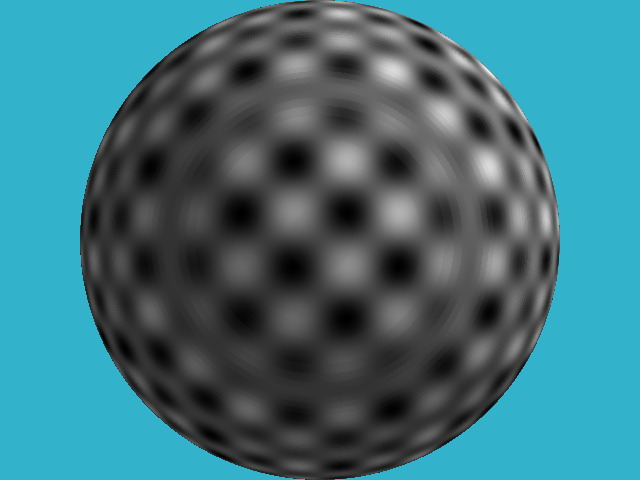
And let's look at some pattern on our field, for example, like this:
For this, in the previous code I changed only two lines!
How did I do it? Of course, I have no textures. I just took the function g (x, y, z) = sin (x) * sin (y) * sin (z); it is again defined in all space. When my ray intersects the sphere at some point, the value of the function g (x, y, z) at this point sets the color of the pixel to me.
By the way, pay attention to the concentric circles on the sphere - these are artifacts of my numerical calculation of the intersection.
Why did I want to draw this pattern? And he will help me to draw such a hedgehog:
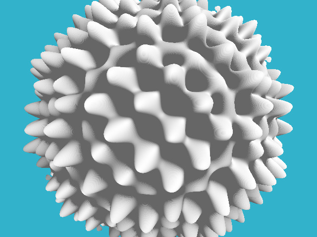
Where my pattern gave a black color, I want to push a hole in our sphere, and where it was white, on the contrary, draw a hump.
To do this, it is enough to change three lines in our code:
That is, I changed the calculation of the distance to our surface, defining it as x ^ 2 + y ^ 2 + z ^ 2 - r ^ 2 - sin (x) * sin (y) * sin (z). In fact, we have defined an implicit function .
And why do I value the product of sines only for points lying on the surface of our sphere? Let's redefine our implicit function like this:
The difference with the previous code is quite small, it is better to look diff . Here is the result:
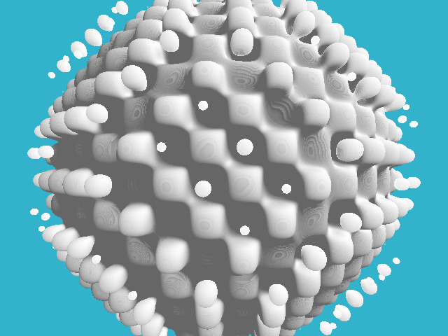
Thus, we can define disconnected components in our object!
The previous picture is already beginning to vaguely resemble an explosion, but the product of the sines has a too regular pattern. We would have some more “ragged”, more “random” function ... Perlin's noise will come to our aid . That's something like that, we would fit much better product sinuses:
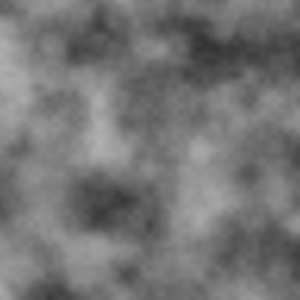
How to generate such a noise - a bit offtopic, but here's the basic idea: you need to generate random images with different resolutions, smooth them out to get something like this set:

And then just their sum:
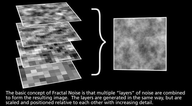
More You can read here and here .
Let's add some code that generates this noise, and we get this picture:
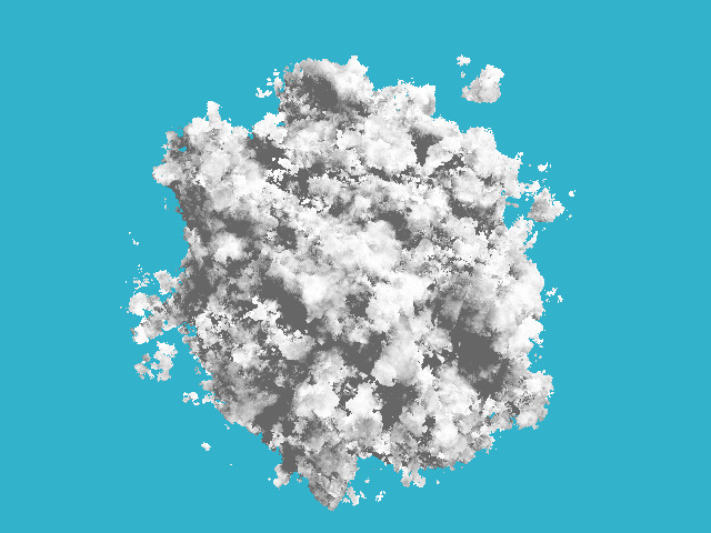
Please note that in the rendering code I didn’t change anything at all, only the function that “hesitates” our sphere has changed.
The only thing I changed in this commit was that, instead of a uniform white color, I imposed a color that depends linearly on the amount of noise applied:
This is a simple linear gradient between five key colors. Well, here's the picture!

This ray tracing technique is called ray marching. Homework is simple: to cross the previous raytracer with blackjack and reflections with our explosion, so much so that the explosion also illuminates everything around! By the way, this explosion is strongly lacking in translucency.
As always, we have only the bare compiler at our disposal, no third-party libraries can be used. I don't want to bother with window managers, mouse / keyboard handling, and the like. The result of our program will be a simple image saved to disk. I absolutely do not chase for speed / optimization, my goal is to show the basic principles.
Total, how in such conditions to draw just such a picture for 180 lines of code?

Let me even insert an animated gif (six meters):

And now we divide the whole task into several stages:
Stage one: read the previous article
Yes exactly. The very first thing you need to read the previous chapter , which tells about the basics of ray tracing. It is quite short, in principle, you can not read any reflections, refractions, but at least I should recommend to finish reading diffused lighting. The code is quite simple, the people run it even on microcontrollers:

Stage two: we draw one sphere
Let's draw one sphere without bothering with materials or lighting. For simplicity, this sphere will live in the center of coordinates. About this picture I want to get:

Look at the code here , but let me give you the main one right in the text of the article:
#define _USE_MATH_DEFINES#include<cmath>#include<algorithm>#include<limits>#include<iostream>#include<fstream>#include<vector>#include"geometry.h"constfloat sphere_radius   = 1.5;
floatsigned_distance(const Vec3f &p){
    return p.norm() - sphere_radius;
}
boolsphere_trace(const Vec3f &orig, const Vec3f &dir, Vec3f &pos){
    pos = orig;
    for (size_t i=0; i<128; i++) {
        float d = signed_distance(pos);
        if (d < 0) returntrue;
        pos = pos + dir*std::max(d*0.1f, .01f);
    }
    returnfalse;
}
intmain(){
    constint   width    = 640;
    constint   height   = 480;
    constfloat fov      = M_PI/3.;
    std::vector<Vec3f> framebuffer(width*height);
#pragma omp parallel forfor (size_t j = 0; j<height; j++) { // actual rendering loopfor (size_t i = 0; i<width; i++) {
            float dir_x =  (i + 0.5) -  width/2.;
            float dir_y = -(j + 0.5) + height/2.;    // this flips the image at the same timefloat dir_z = -height/(2.*tan(fov/2.));
            Vec3f hit;
            if (sphere_trace(Vec3f(0, 0, 3), Vec3f(dir_x, dir_y, dir_z).normalize(), hit)) { // the camera is placed to (0,0,3) and it looks along the -z axis
                framebuffer[i+j*width] = Vec3f(1, 1, 1);
            } else {
                framebuffer[i+j*width] = Vec3f(0.2, 0.7, 0.8); // background color
            }
        }
    }
    std::ofstream ofs("./out.ppm", std::ios::binary); // save the framebuffer to file
    ofs << "P6\n" << width << " " << height << "\n255\n";
    for (size_t i = 0; i < height*width; ++i) {
        for (size_t j = 0; j<3; j++) {
            ofs << (char)(std::max(0, std::min(255, static_cast<int>(255*framebuffer[i][j]))));
        }
    }
    ofs.close();
    return0;
}
The class of vectors lives in the geometry.h file, I will not describe it here: first, everything is trivial, simple manipulation of two and three-dimensional vectors (addition, subtraction, assignment, scalar multiplication, scalar production), and second, gbg has already described it in detail as part of a course on computer graphics.
I save the picture in ppm format ; This is the easiest way to save images, although it is not always the most convenient for further viewing.
So, in the function main (), I have two cycles: the second cycle simply saves the image to the disk, and the first cycle passes through all the pixels of the image, emits a beam from the camera through this pixel, and looks to see if this beam intersects with our sphere.
Attention, the main idea of the article: if in the last article we analytically considered the intersection of the ray and the sphere, now I consider it numerically. The idea is simple: a sphere has an equation of the form x ^ 2 + y ^ 2 + z ^ 2 - r ^ 2 = 0; but in general the function f (x, y, z) = x ^ 2 + y ^ 2 + z ^ 2 - r ^ 2 is defined in the whole space. Inside the sphere, the function f (x, y, z) will have negative values, and outside the sphere will be positive. That is, the function f (x, y, z) for the point (x, y, z) sets the distance (with a sign!) To our sphere. Therefore, we will simply slide along the ray until either we are bored or the function f (x, y, z) becomes negative. The function sphere_trace () does just that.
Stage Three: Primitive Lighting
Let's code the simplest diffuse lighting, this is the picture I want to get at the output:

As in the previous article, for ease of reading I made one stage = one commit. Changes can be viewed here .
For diffuse illumination it is not enough for us to calculate the point of intersection of the beam with the surface, we need to know the vector of the normal to the surface at this point. I obtained this normal vector by simple finite differences in our function of the distance to the surface:
Vec3f distance_field_normal(const Vec3f &pos){
    constfloat eps = 0.1;
    float d = signed_distance(pos);
    float nx = signed_distance(pos + Vec3f(eps, 0, 0)) - d;
    float ny = signed_distance(pos + Vec3f(0, eps, 0)) - d;
    float nz = signed_distance(pos + Vec3f(0, 0, eps)) - d;
    return Vec3f(nx, ny, nz).normalize();
}
In principle, of course, since we draw a sphere, the normal can be obtained much easier, but I did so with the groundwork for the future.
Stage four: let's draw a pattern on our sphere
And let's look at some pattern on our field, for example, like this:

For this, in the previous code I changed only two lines!
How did I do it? Of course, I have no textures. I just took the function g (x, y, z) = sin (x) * sin (y) * sin (z); it is again defined in all space. When my ray intersects the sphere at some point, the value of the function g (x, y, z) at this point sets the color of the pixel to me.
By the way, pay attention to the concentric circles on the sphere - these are artifacts of my numerical calculation of the intersection.
Stage Five: displacement mapping
Why did I want to draw this pattern? And he will help me to draw such a hedgehog:

Where my pattern gave a black color, I want to push a hole in our sphere, and where it was white, on the contrary, draw a hump.
To do this, it is enough to change three lines in our code:
floatsigned_distance(const Vec3f &p){
    Vec3f s = Vec3f(p).normalize(sphere_radius);
    float displacement = sin(16*s.x)*sin(16*s.y)*sin(16*s.z)*noise_amplitude;
    return p.norm() - (sphere_radius + displacement);
}
That is, I changed the calculation of the distance to our surface, defining it as x ^ 2 + y ^ 2 + z ^ 2 - r ^ 2 - sin (x) * sin (y) * sin (z). In fact, we have defined an implicit function .
Stage Six: Another Implicit Function
And why do I value the product of sines only for points lying on the surface of our sphere? Let's redefine our implicit function like this:
floatsigned_distance(const Vec3f &p){
    float displacement = sin(16*p.x)*sin(16*p.y)*sin(16*p.z)*noise_amplitude;
    return p.norm() - (sphere_radius + displacement);
}
The difference with the previous code is quite small, it is better to look diff . Here is the result:

Thus, we can define disconnected components in our object!
Stage Seven: pseudo-random noise
The previous picture is already beginning to vaguely resemble an explosion, but the product of the sines has a too regular pattern. We would have some more “ragged”, more “random” function ... Perlin's noise will come to our aid . That's something like that, we would fit much better product sinuses:

How to generate such a noise - a bit offtopic, but here's the basic idea: you need to generate random images with different resolutions, smooth them out to get something like this set:

And then just their sum:

More You can read here and here .
Let's add some code that generates this noise, and we get this picture:

Please note that in the rendering code I didn’t change anything at all, only the function that “hesitates” our sphere has changed.
Stage eight, final: add color
The only thing I changed in this commit was that, instead of a uniform white color, I imposed a color that depends linearly on the amount of noise applied:
Vec3f palette_fire(constfloat d){
    const Vec3f   yellow(1.7, 1.3, 1.0); // note that the color is "hot", i.e. has components >1const Vec3f   orange(1.0, 0.6, 0.0);
    const Vec3f      red(1.0, 0.0, 0.0);
    const Vec3f darkgray(0.2, 0.2, 0.2);
    const Vec3f     gray(0.4, 0.4, 0.4);
    float x = std::max(0.f, std::min(1.f, d));
    if (x<.25f)
        return lerp(gray, darkgray, x*4.f);
    elseif (x<.5f)
        return lerp(darkgray, red, x*4.f-1.f);
    elseif (x<.75f)
        return lerp(red, orange, x*4.f-2.f);
    return lerp(orange, yellow, x*4.f-3.f);
}
This is a simple linear gradient between five key colors. Well, here's the picture!

Conclusion
This ray tracing technique is called ray marching. Homework is simple: to cross the previous raytracer with blackjack and reflections with our explosion, so much so that the explosion also illuminates everything around! By the way, this explosion is strongly lacking in translucency.
