Building a quadcopter, part three
Part 1 | Part 2 | Part 3 | Part 4 We
continue to stretch our brains and gain new skills.
While we were torturing gyroscopes and accelerometers, a more detailed diagram of the apparatus appeared in our heads and on paper, taking into account the assumption that the stabilization functions and other functions should be divided between two independent processors:
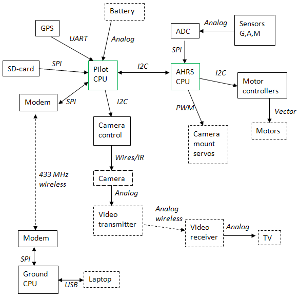
AHRS CPU - receivesdigitized data from sensors(for example, let it be two low-cost MCP3208 operating on the SPI bus) (it’s enough for the eyes 50 times per second), filters them, calculates the tilt of the device, calculates the propeller speed needed to stabilize (possibly by the PID control algorithm, the simplest and most popular), sends the values of these speeds to the motor controllers on the I2C bus, and those, in turn, feed the motors (vector control, if not mistaken). There is still a bunch of free legs and a little computing ability to control the servos that align the camera (servos are standardly controlled by a PWM signal).
Sensors - previously described 3 gyroscopes, 3-axis accelerometer, 3-axis magnetometer (shows excellent orientation in a plane parallel to the ground), optionally - a pressure sensor for measuring height. All sensors can easily be taken analog, they are cheaper, the two above-mentioned microcircuits will be engaged in fast ADC conversion (one does not have enough channels).
Pilot CPU- directly autopilot, setting the second microcontroller the desired tilt of the apparatus and camera and providing communication with the ground. He also measures the voltage on the battery, receives coordinates from GPS (possibly to fly to the key points recorded on the SD card, or record your route on it) and sends commands to the camera controller.
Camera control - a microcontroller that will be useful for controlling the camera (shutter, zoom, etc.). It can transmit commands to the camera via IR , or directly by wires.
Video transmitter - it’s most convenient to take a standard one , this one is used in security video systems.
Radio modems - you can take the popular X-Bee, working on ZigBee protocols(2.4 GHz), but some modem based on the SS1100 chipset (433 MHz) will be much cheaper, it has good characteristics and a detailed datasheet.
A laptop will be used as a control panel (as well as to display the status of devices), and another microcontroller will be needed to communicate with the modem.
For our purposes, the processing power of two ATmega microcontrollers will be quite enough (for others we do not know how to write software at all), the binding for them is minimal. We draw the standard wiring of the input / output ports of the microcontrollers to the connectors, to which we then attach the peripheral devices on the docking boards.
The important point is that peripheral devices operate at different voltages: servo machines and motor controllers at 5 V, and a modem, gps, sensors and an SD card - at 3.3. Fortunately, the stress distribution turned out to be beneficial. The microcontroller responsible for multicopter stabilization will operate at 5 V (this will also enable us to use it at a frequency of 16 MHz), it is also connected to the five-voltage I2C bus leading to the motor controllers, and the five-voltage SPI connected to the five-voltage ADC (with on the other hand, the ADC compares the signals from the three-volt sensors with the three-volt reference, so that everything fits together). The microcontroller pilot operates at 3.3 V (which limits its clock frequency to 8 MHz, but we no longer need it), and is connected to the rest of the peripherals via 3.3 V buses. The question remains how to connect the two microcontrollers.
It should be noted that before that I almost did not deal with electronics, and much was new to me. But my companion helped me in our multicopter business (the described scheme was born in lengthy discussions with him). I started to draw it all in Sprint Layout, but this friend advised Proteus, and it was very practical advice. Proteus is a wonderful and convenient system for designing circuits, so I advise it to everyone who is going to do this difficult task.
Next, we draw a diagram with all our devices: I don’t remember why I didn’t capture the whole diagram when I was preparing screenshots for publication, but the frame did not include only a couple of connectors and a power supply unit that provided us with separate power supply of 5 V, 3.3 V, and Separately filtered 3.3 V to power sensors.
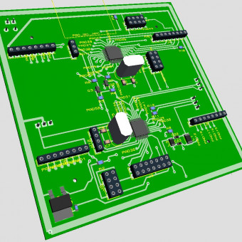
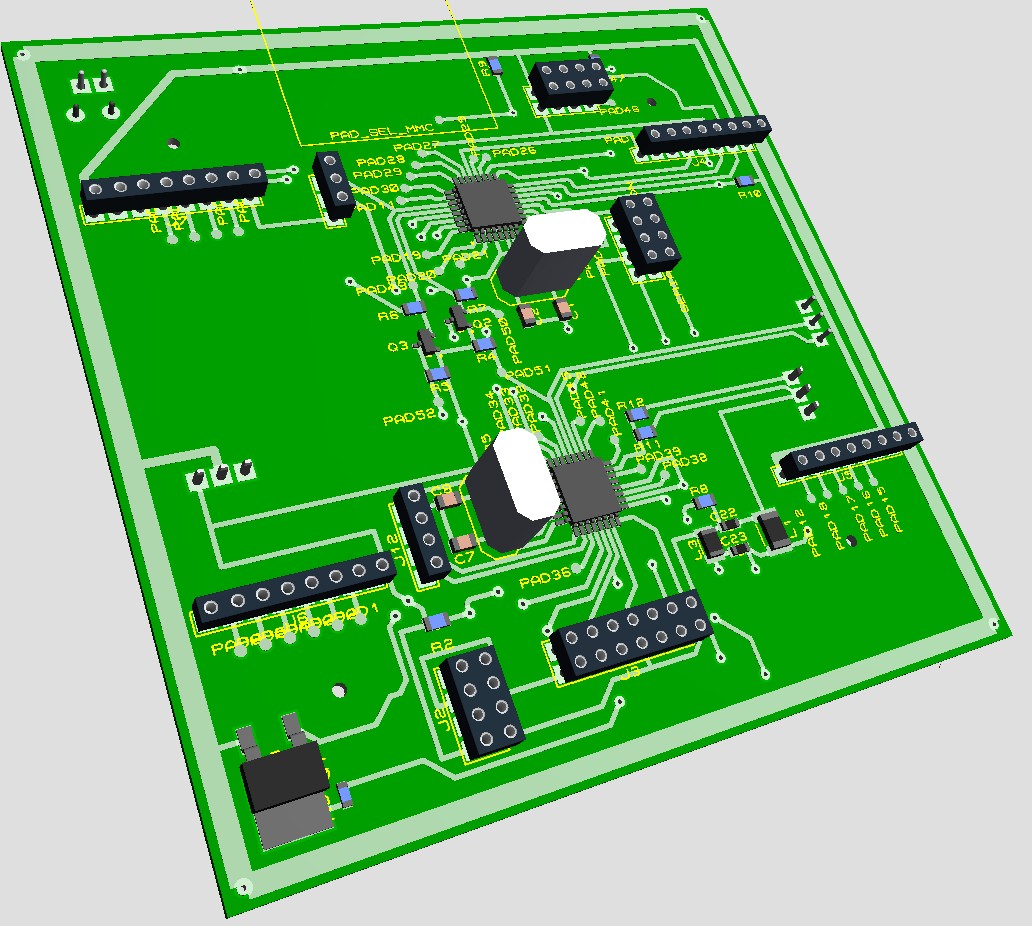
We switch to the board layout mode, and here the most creative process begins. When a compromise is found between perfectionism and curvature, you can relax by turning on the 3D visualization of the resulting board: The entire board took about 15 centimeters in width and the same in length. Similarly, we draw the docking boards for peripheral devices (these docking boards can be conveniently inserted into the connectors of the "motherboard").


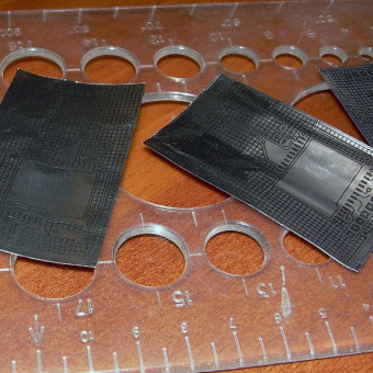
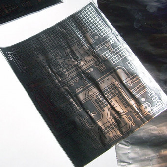
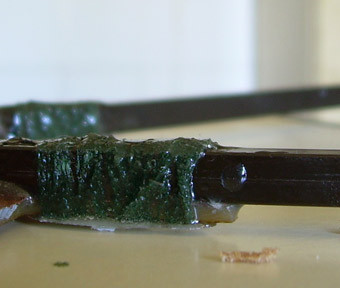
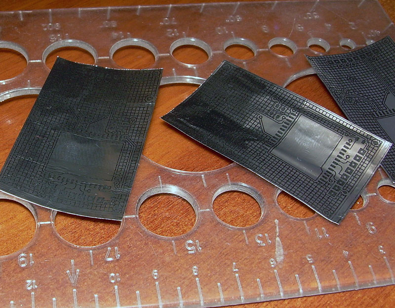
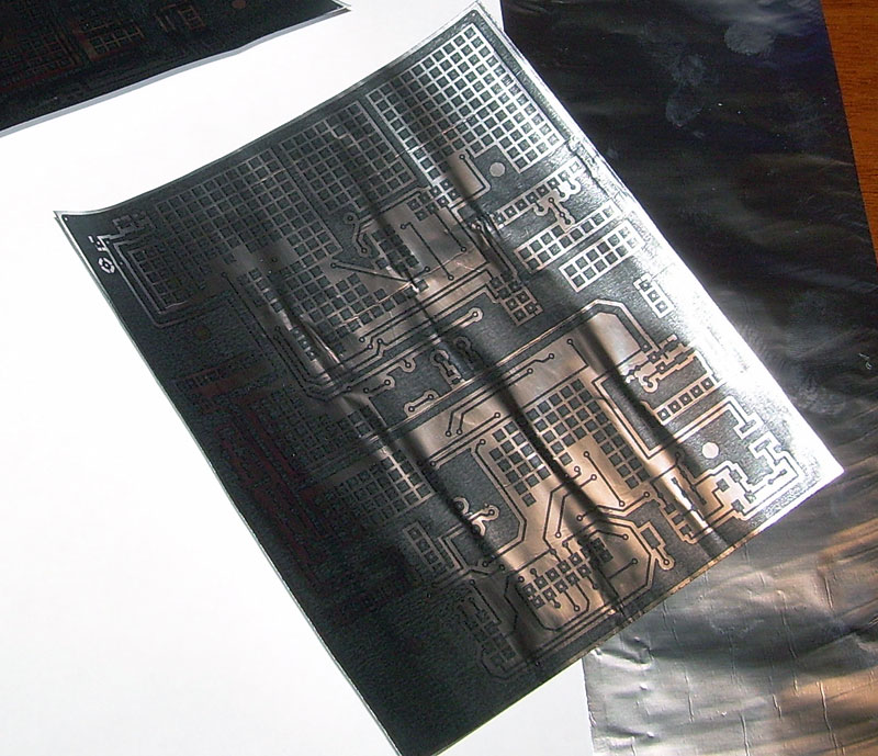
We made them using a slightly different technology, beautifully described by LJ-user alex_avr2. Its essence is that the pattern of the tracks is printed directly on the foil (it is rather scary to load paper in the foil into the printer), and then, after pressing it with an iron, the board is etched with the foil. Due to the fact that it is not necessary to peel off the substrate, the picture is clear and beautiful. Another tip for those who decide to do electronics is that the quality of this method is much higher, the reject rate is lower, and production is easier.
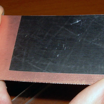
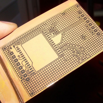
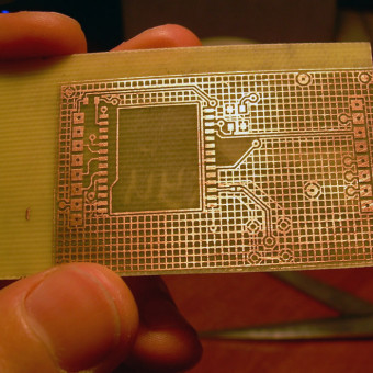
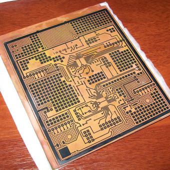
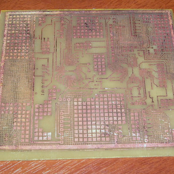
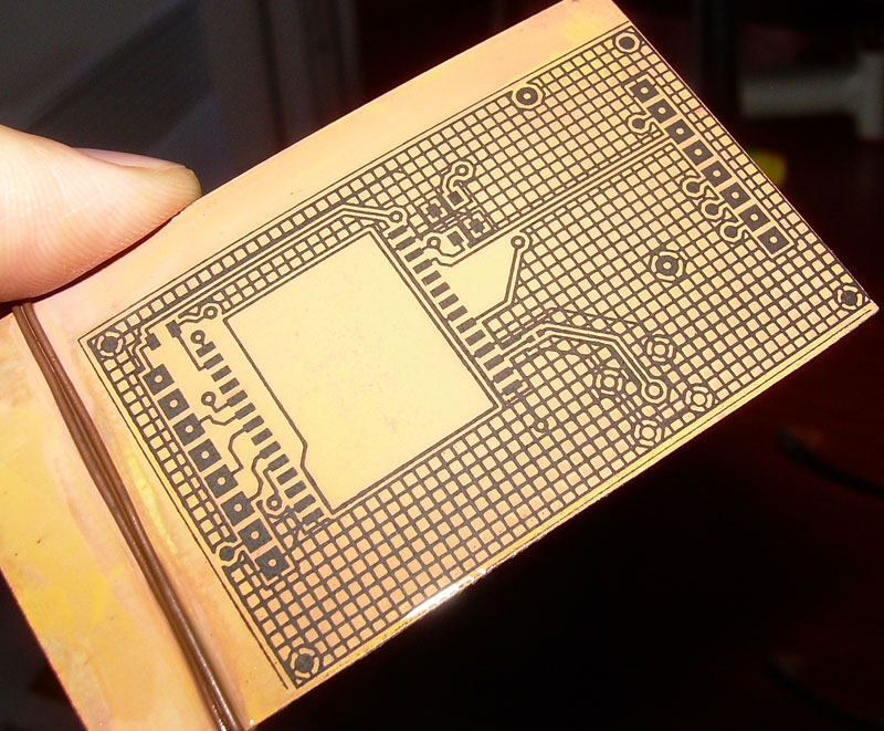
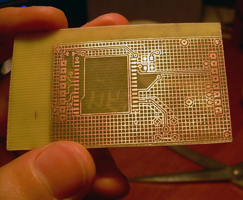
We are making a GPS docking board: And the main board: (in the second picture you can see the relief of the tracks showing up after pressing the foil with an iron, but in the last one it’s not as bad as it seems, it's just grinding like that)


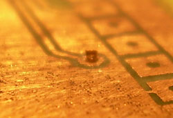
Now you need to drill and metallize the holes to create contacts between the two layers of the board. At home, it is extremely difficult to achieve an “honest” metallization (when the metal settles on the walls of the hole), so a copper wire is inserted into the hole and sealed on both sides. However, I decided to try a small variation of this method with the riveting of the wire (this way it sticks out less and is easier to solder). Two things that we wound around the mustache this time: it’s very difficult to drill a lot of holes with a homemade mini-drill, and if you rivet the wire, you need to do more contact circles.
And yet, for convenient wire feed, it can be tucked into an automatic pencil instead of a stylus, and a simple device will help to drill holes strictly perpendicular to the board. However, perpendicular drilling will not help if the layers of the board are not aligned precisely enough, therefore, for those who have hands like mine, I advise you to still use a photoresist .
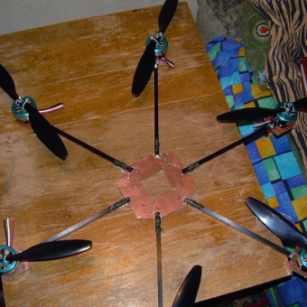
Entertainment for the sake of, I will tell you how not to make a frame. It does not need to be made of flimsy PCB and carbon fiber profiles with a cross section of 5x5 mm, they will not withstand anything more than 300 grams of a quadrocopter, for our purposes we need at least 1.5 mm aluminum and aluminum pipes of a centimeter diameter. Well, if you want absolutely beauty, strength and low weight, there is only one option: carbon fiber in several layers, impregnated with epoxy resin (“carbon”). In the last photo, it is noticeable that characterizes the concept of Epic fail: the ends of the propellers touch each other. I don’t know why, but I didn’t succeed from the first (and also below) the first time. If it was possible to screw something on the wrong side, I definitely did it, although I checked it before more than once. It’s sad.

I have some good and bad news for you. The bad thing is that all “creativity” ends there. We realized that the project has already spent more than a thousand dollars and about a year of time, and the results, to put it mildly, are just around the corner. Writing software more or less from scratch requires at least another six months of time, and debugging requires as much more. And taking into account my curvature and limited finances, we can say with confidence “it will not fly up”.
It is sad of course, but we did not pull this project. I want to believe that someone will do it better than ours, and I will gladly help such people with advice and information that was deposited in my head and on the hard drive after studying a large amount of material.
But there is good news: in the next part, we will finally move on to practice, and yet we will assemble this shaitan machine (although again not without misfires), however, already on ready-made software and hardware. Thank you for your interest in this topic and useful comments on the previous (and possibly this) parts.
The development of electronic devices is a very interesting and fascinating activity. But without experience in this matter and a team of inspired and energetic colleagues, the bottom line is only experience. Well, and maybe a boring thesis.
Do not overestimate your strengths, recruit more people (two heads are better than one, however, like two wallets), preferably professionals in any of the relevant areas, and you will get many times more than ours.
To be continued.
continue to stretch our brains and gain new skills.
While we were torturing gyroscopes and accelerometers, a more detailed diagram of the apparatus appeared in our heads and on paper, taking into account the assumption that the stabilization functions and other functions should be divided between two independent processors:
Quadcopter Components
AHRS CPU - receivesdigitized data from sensors(for example, let it be two low-cost MCP3208 operating on the SPI bus) (it’s enough for the eyes 50 times per second), filters them, calculates the tilt of the device, calculates the propeller speed needed to stabilize (possibly by the PID control algorithm, the simplest and most popular), sends the values of these speeds to the motor controllers on the I2C bus, and those, in turn, feed the motors (
Sensors - previously described 3 gyroscopes, 3-axis accelerometer, 3-axis magnetometer (shows excellent orientation in a plane parallel to the ground), optionally - a pressure sensor for measuring height. All sensors can easily be taken analog, they are cheaper, the two above-mentioned microcircuits will be engaged in fast ADC conversion (one does not have enough channels).
Pilot CPU- directly autopilot, setting the second microcontroller the desired tilt of the apparatus and camera and providing communication with the ground. He also measures the voltage on the battery, receives coordinates from GPS (possibly to fly to the key points recorded on the SD card, or record your route on it) and sends commands to the camera controller.
Camera control - a microcontroller that will be useful for controlling the camera (shutter, zoom, etc.). It can transmit commands to the camera via IR , or directly by wires.
Video transmitter - it’s most convenient to take a standard one , this one is used in security video systems.
Radio modems - you can take the popular X-Bee, working on ZigBee protocols(2.4 GHz), but some modem based on the SS1100 chipset (433 MHz) will be much cheaper, it has good characteristics and a detailed datasheet.
A laptop will be used as a control panel (as well as to display the status of devices), and another microcontroller will be needed to communicate with the modem.
Main Board Design
For our purposes, the processing power of two ATmega microcontrollers will be quite enough (for others we do not know how to write software at all), the binding for them is minimal. We draw the standard wiring of the input / output ports of the microcontrollers to the connectors, to which we then attach the peripheral devices on the docking boards.
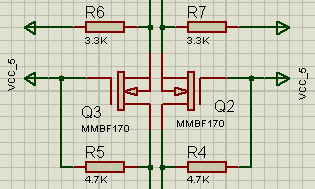
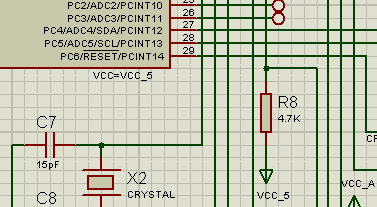
The important point is that peripheral devices operate at different voltages: servo machines and motor controllers at 5 V, and a modem, gps, sensors and an SD card - at 3.3. Fortunately, the stress distribution turned out to be beneficial. The microcontroller responsible for multicopter stabilization will operate at 5 V (this will also enable us to use it at a frequency of 16 MHz), it is also connected to the five-voltage I2C bus leading to the motor controllers, and the five-voltage SPI connected to the five-voltage ADC (with on the other hand, the ADC compares the signals from the three-volt sensors with the three-volt reference, so that everything fits together). The microcontroller pilot operates at 3.3 V (which limits its clock frequency to 8 MHz, but we no longer need it), and is connected to the rest of the peripherals via 3.3 V buses. The question remains how to connect the two microcontrollers.
It should be noted that before that I almost did not deal with electronics, and much was new to me. But my companion helped me in our multicopter business (the described scheme was born in lengthy discussions with him). I started to draw it all in Sprint Layout, but this friend advised Proteus, and it was very practical advice. Proteus is a wonderful and convenient system for designing circuits, so I advise it to everyone who is going to do this difficult task.
Next, we draw a diagram with all our devices: I don’t remember why I didn’t capture the whole diagram when I was preparing screenshots for publication, but the frame did not include only a couple of connectors and a power supply unit that provided us with separate power supply of 5 V, 3.3 V, and Separately filtered 3.3 V to power sensors.
We switch to the board layout mode, and here the most creative process begins. When a compromise is found between perfectionism and curvature, you can relax by turning on the 3D visualization of the resulting board: The entire board took about 15 centimeters in width and the same in length. Similarly, we draw the docking boards for peripheral devices (these docking boards can be conveniently inserted into the connectors of the "motherboard").


Board making
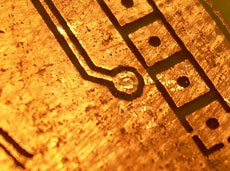
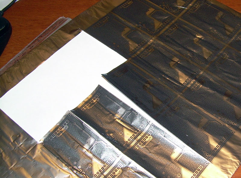
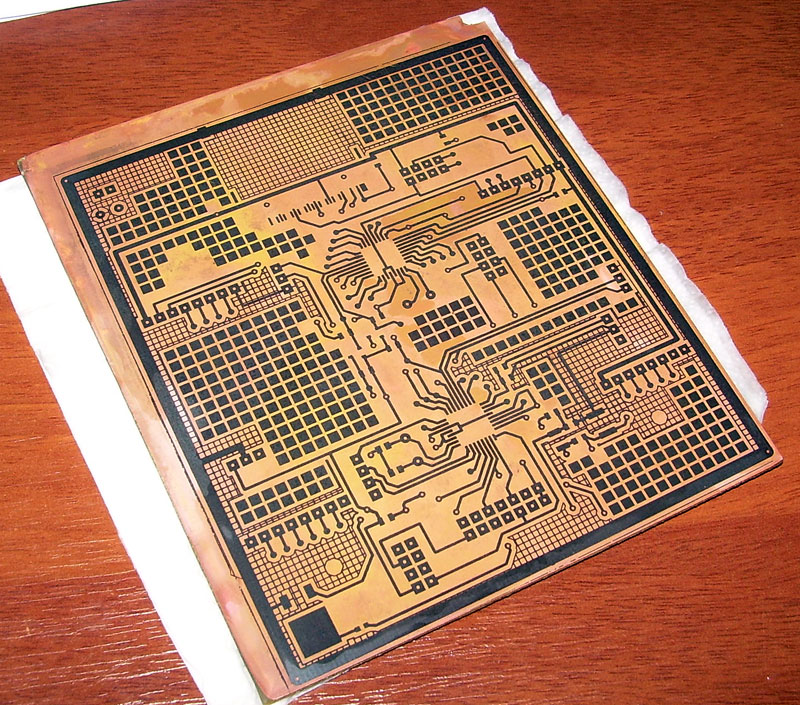
We made them using a slightly different technology, beautifully described by LJ-user alex_avr2. Its essence is that the pattern of the tracks is printed directly on the foil (it is rather scary to load paper in the foil into the printer), and then, after pressing it with an iron, the board is etched with the foil. Due to the fact that it is not necessary to peel off the substrate, the picture is clear and beautiful. Another tip for those who decide to do electronics is that the quality of this method is much higher, the reject rate is lower, and production is easier.
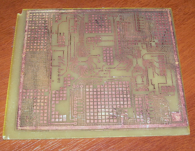
We are making a GPS docking board: And the main board: (in the second picture you can see the relief of the tracks showing up after pressing the foil with an iron, but in the last one it’s not as bad as it seems, it's just grinding like that)


Now you need to drill and metallize the holes to create contacts between the two layers of the board. At home, it is extremely difficult to achieve an “honest” metallization (when the metal settles on the walls of the hole), so a copper wire is inserted into the hole and sealed on both sides. However, I decided to try a small variation of this method with the riveting of the wire (this way it sticks out less and is easier to solder). Two things that we wound around the mustache this time: it’s very difficult to drill a lot of holes with a homemade mini-drill, and if you rivet the wire, you need to do more contact circles.
And yet, for convenient wire feed, it can be tucked into an automatic pencil instead of a stylus, and a simple device will help to drill holes strictly perpendicular to the board. However, perpendicular drilling will not help if the layers of the board are not aligned precisely enough, therefore, for those who have hands like mine, I advise you to still use a photoresist .
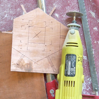
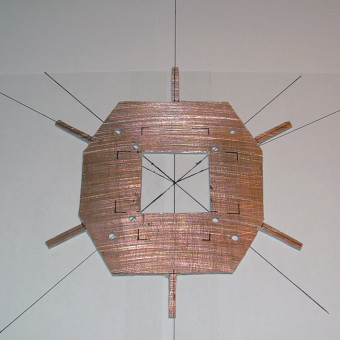
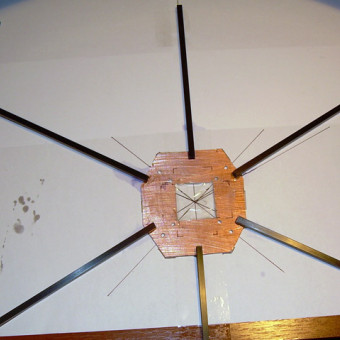
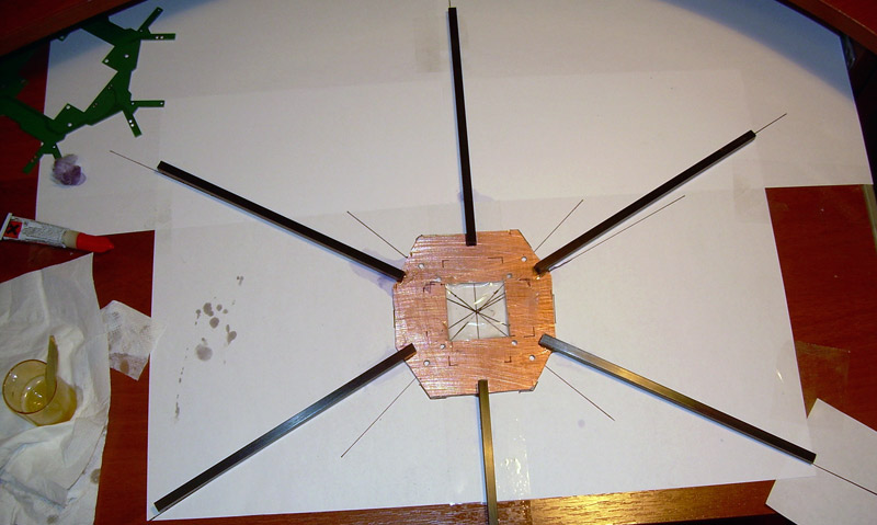
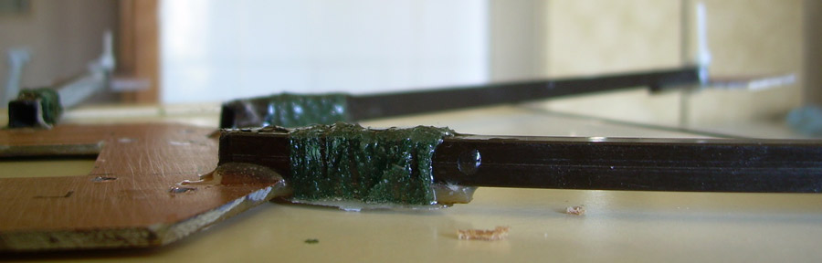
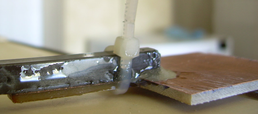
Rama, the first attempt
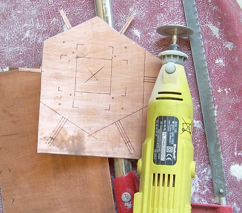
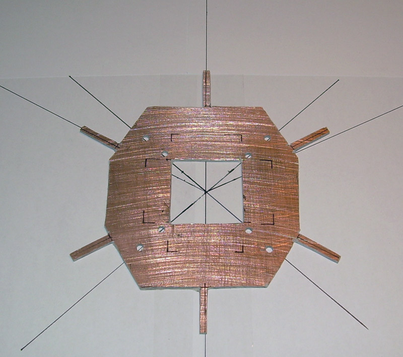
Entertainment for the sake of, I will tell you how not to make a frame. It does not need to be made of flimsy PCB and carbon fiber profiles with a cross section of 5x5 mm, they will not withstand anything more than 300 grams of a quadrocopter, for our purposes we need at least 1.5 mm aluminum and aluminum pipes of a centimeter diameter. Well, if you want absolutely beauty, strength and low weight, there is only one option: carbon fiber in several layers, impregnated with epoxy resin (“carbon”). In the last photo, it is noticeable that characterizes the concept of Epic fail: the ends of the propellers touch each other. I don’t know why, but I didn’t succeed from the first (and also below) the first time. If it was possible to screw something on the wrong side, I definitely did it, although I checked it before more than once. It’s sad.

The section that I did not want to write
I have some good and bad news for you. The bad thing is that all “creativity” ends there. We realized that the project has already spent more than a thousand dollars and about a year of time, and the results, to put it mildly, are just around the corner. Writing software more or less from scratch requires at least another six months of time, and debugging requires as much more. And taking into account my curvature and limited finances, we can say with confidence “it will not fly up”.
It is sad of course, but we did not pull this project. I want to believe that someone will do it better than ours, and I will gladly help such people with advice and information that was deposited in my head and on the hard drive after studying a large amount of material.
But there is good news: in the next part, we will finally move on to practice, and yet we will assemble this shaitan machine (although again not without misfires), however, already on ready-made software and hardware. Thank you for your interest in this topic and useful comments on the previous (and possibly this) parts.
Conclusion
The development of electronic devices is a very interesting and fascinating activity. But without experience in this matter and a team of inspired and energetic colleagues, the bottom line is only experience. Well, and maybe a boring thesis.
Do not overestimate your strengths, recruit more people (two heads are better than one, however, like two wallets), preferably professionals in any of the relevant areas, and you will get many times more than ours.
To be continued.